ELECRAFT K3 User manual

ELECRAFTK3
HIGH-PERFORMANCE
160 –6 METER TRANSCEIVER
OWNER’SMANUAL
Revision D1, July 27, 2008
Copyright © 2008, Elecraft, Inc.
All Rights Reserved

2
Contents
A Noteto K3 Owners.......................................3
Key to Symbols and Text Styles.......................3
Quick-Start Guide.............................................4
Introduction.......................................................7
K3 Features.....................................................7
Specifications..................................................8
Customer Service and Support........................10
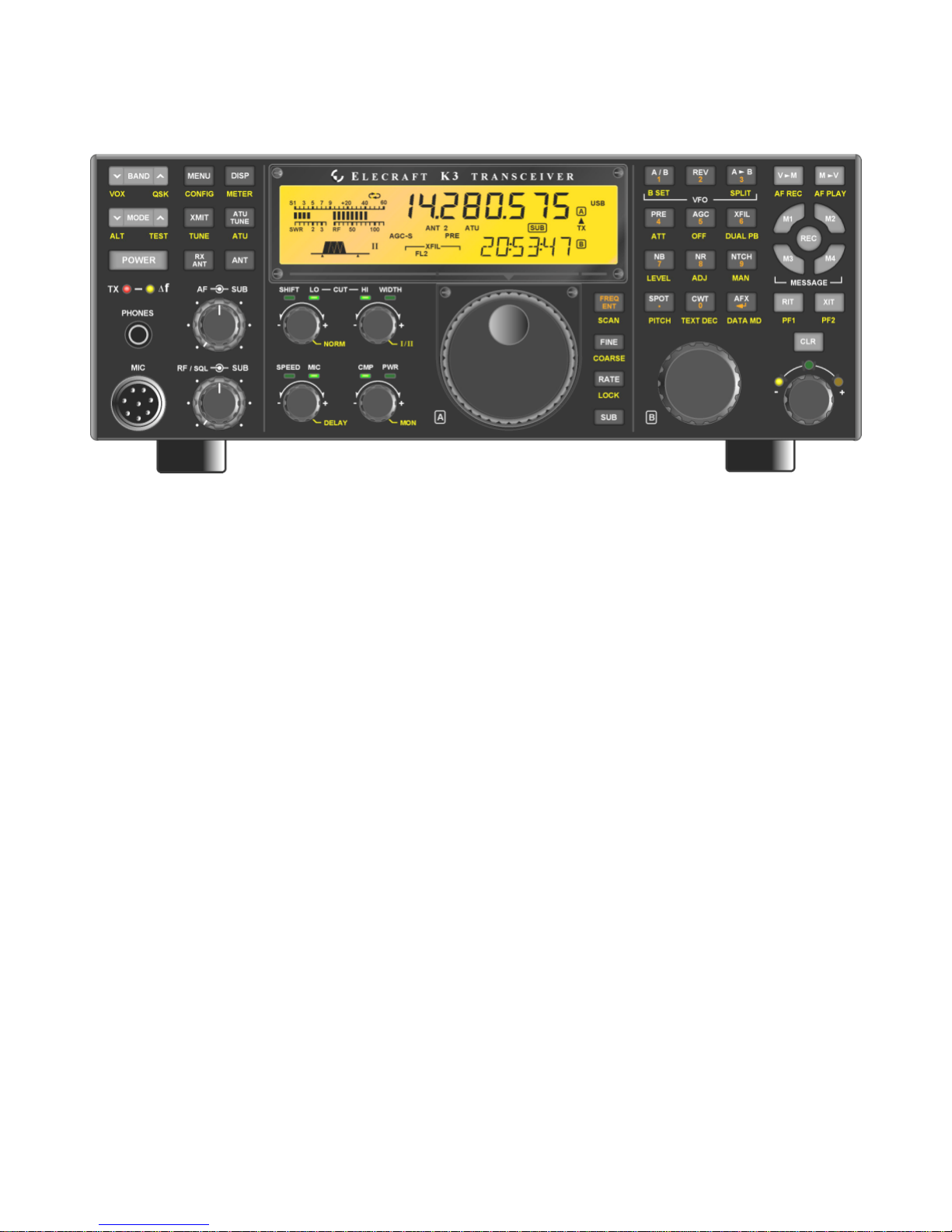
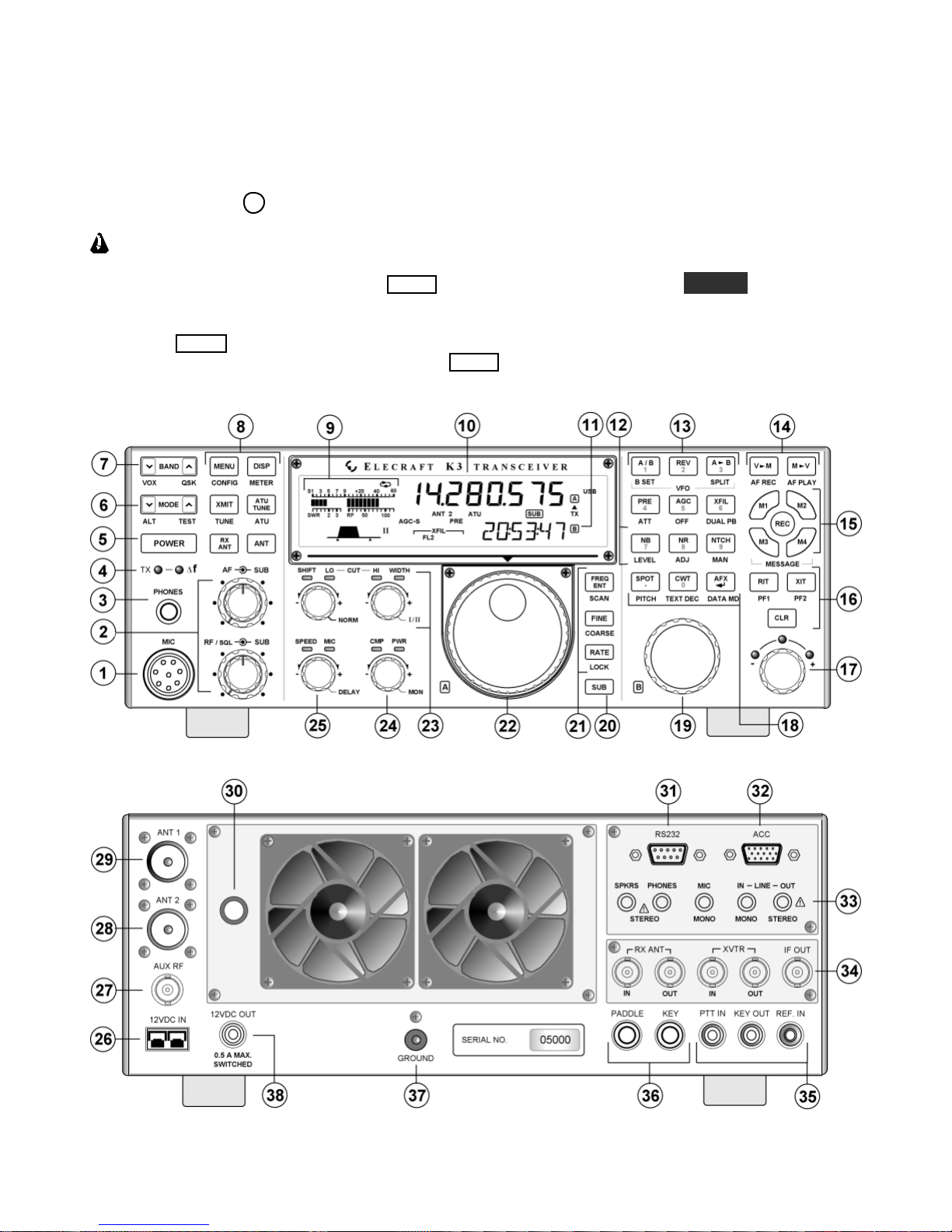
Front Panel......................................................11
ControlGroups..............................................11
Display.........................................................12
LEDs............................................................13
Front Panel Connectors..................................13
Primary Controls...........................................13
Multi-Function Controls.................................14
VFO Tuning Controls....................................14
Keypad.........................................................15
Memory Controls..........................................16
Message Record/Play Controls.......................16
RIT and XIT Controls....................................16
Rear Panel.......................................................17
Connector Groups..........................................17
KIO3 Module................................................18
Basic Operation..............................................21
Receiver Setup..............................................23
Reducing Interference and Noise....................25
Transmitter Setup..........................................26
Voice Modes (SSB, AM, FM)........................28
CW Mode.....................................................30
Data Modes...................................................31
Advanced OperatingFeatures.........................33
Text Decode And Display..............................33
CW-to-DATA...............................................34
Tuning Aids: CWT and SPOT........................34
Audio Effects (AFX)......................................35
Dual Passband CW Filtering...........................35
Receive Audio Equalization (EQ)...................35
Transmit Audio Equalization (EQ)..................35
SPLIT and Cross-Mode Operation..................36
Extended Single Sideband (ESSB)..................36
General-Coverage Receive.............................36
VFO B AlternateDisplays..............................36
Alarm and Auto Power-On.............................36
Using the Sub Receiver..................................37
Receive Antenna In/Out.................................38
Buffered I.F. Output...................................... 38
Using Transverters........................................ 38
Scanning...................................................... 39
Main and Sub Receiver Antenna Routing......40
Basic K3 (no KAT3 or KXV3) ...................... 40
K3 with KXV3 RF I/O Module...................... 40
K3 with KAT3 ATU..................................... 41
K3 with KAT3 and KXV3............................. 42
Remote Control of the K3..............................43
Options...........................................................44
Firmware Upgrades........................................44
Configuration.................................................45
Crystal Filter Setup....................................... 45
Option Module Enables................................. 46
Miscellaneous Setup...................................... 46
VFO A Knob Friction Adjustment................. 47
VFO B Knob Friction Adjustment.................. 47
Real Time Clock Battery Replacement........... 47
Calibration Procedures...................................48
Synthesizer................................................... 48
Wattmeter..................................................... 48
Transmitter Gain........................................... 48
ReferenceOscillator......................................49
Front Panel Temperature Sensor.................... 50
PATemperature Sensor................................. 50
S-Meter........................................................ 50
Menu Functions..............................................51
MAIN Menu................................................. 51
CONFIG Menu............................................. 52
Troubleshooting.............................................59
Parameter Initialization................................. 61
Module Troubleshooting............................... 62
Theory Of Operation......................................66
RF BOARD.................................................. 66
KANT3 and KAT3....................................... 68
KIO3............................................................ 68
Front Panel and DSP..................................... 68
KREF3......................................................... 69
KSYN3 ........................................................ 70
K3 Block Diagram........................................ 71
AppendixA: Crystal Filter Installation..........72
Index...............................................................76

3
A Note to K3 Owners
On behalf of our entire design team, we’d like to thank you for choosing the Elecraft K3 transceiver.
The K3—like its predecessor, the K2—reflects our desire to go beyond what other high-performance
transceivers have offered. It isn’t just a home-station rig; at about 8 to 9pounds, it can accompany you
wherever you go, whether it’s out to your back porch or halfway around the world. And it’s the only
rig in its class that you can build yourself. Above all, we want the K3 to be ready for any operating
situation you encounter, and be more enjoyable to use than any transceiver you’ve ever owned.
In addition to this manual, you’ll find much more information on the K3 on our web site, including
operatingtips, answers to frequently asked questions, and information on firmware upgrades.
73,
Wayne, N6KR
Eric, WA6HHQ
Key to Symbols and Text Styles
Important –read carefully
Operating tip
LSB
. .
LCD icon or characters
LED
Enter keypad function
XMIT
TUNE
Tap switch function (labeled on a switch)
Hold switch function (labeled below a switch;hold for 1/2 sec. to activate)
SQL
PWR
MON
Rotary control without integral switch
Tap switch function of rotary control (labeled above a knob)
Hold switch function of rotary control (labeled below a knob; hold for 1/2 sec.)
MAIN:VOX GN Typical MAIN menu entry
CONFIG:KAT3 Typical CONFIG menu entry

4
Quick-Start Guide
To get started using your K3 right away, please readthispage andthe two that follow, trying each of the
controls. The text uses braces to referto numbered elements in the front- and rear-panel illustrations below. For
example, {1}refers to 1, the mic jack. Later sectionsprovide greater detail on all aspectsof K3 operation.
The first thing you needto know about the K3 isthat most switches have two functions. Tap (press
briefly) to activatethe function labeled on a switch. Hold to activatethe function labeled below the switch. In
the text, tap functions are shown like this: MENU . An example of a hold function is CONFIG . Additional
typographical conventions are shown on the previous page.
Try tapping MENU {8}. This brings up the MAIN menu. Rotating VFO B {19} selects menu entries, while
rotating VFO A {22} changestheir parameters. Tap MENU againto exit the menu.

5
Connections Connect a power supplyto the DC input jack {26}(see Specifications, pg. 8).
On the K3/100, a circuit breaker is provided on the fan panel for the 100-W stage {30}
.
You can power an accessory device from the switched DC output jack {38}(0.5 A max).
Connect an antenna to ANT1 {29}. If you have an ATU installed (pg. 22), you can connect
a second antenna to ANT2 {28}. Ifthe KXV3 is installed, you can connect a separate RX
antenna to RX ANT IN {34}. The AUX RF connector {27} is optional; see pg. 17.
The Basics Press POWER {5}to turn on the K3. If there are any error indications, refer to pg. 63.
TAP and HOLD Functions: Tapping briefly activatesthe function labeled on
a switch.
Holding for about 1/2 second activatesthe function labeled below a switch.
Tap either end of BAND {7}to select a band, andtap MODE {6}to select the mode. Set
the AF gain using AF {2}. Set RF to max. SUB controls are discussed on pg. 37.
The large knob {22} controls VFO A (upper display, {10}). The medium knob {19}
controls VFO B (lower display, {11}). VFO A is main RX/TX except in SPLIT (pg. 36).
CMP /PWR is one of four multifunction controls {24}. Each hastwo primary
functions, indicated by green LEDs. The knob has a built-in switch; tap it to select either
CMP (compression level) or PWR (power output). Holdthe knob in to access its
secondary function, MONitor level. Tap again to restore the primary function.
Filter
Controls
Rotate the SHIFT/ LOCUT and HICUT/ WIDTH controls {23}to adjust the filter
passband. Crystal filters FL1-FL5 are automatically selected as you change the
bandwidth. Tap either knobto alternate between shift/width and hicut/locut.
Hold SHIFT/ LOCUT to NORM
alize the bandwidth (e.g., 400 Hz CW, 2.8 kHz SSB).
Hold HICUT/ WIDTH to alternate between two filter setups, Iand II (per-mode).
Tap XFIL {13} to select crystalfilters manually; this also removes any passband shift.
Voice Modes
{1}
Hold METER {8}to see CMP /ALC levels. Whiletalking, set MIC {25} for 4-7 bars
of ALC, and CMP for the desired compression. Then return to SWR /PWR (pg. 28).
Optional: Hold TEST {6} for TX TESTmode; allows off-air TX adjustments (pg. 13).
Hold CMP / PWR {24}to set speech MONitor level;tap to returnto CMP /PWR.
Hold VOX {7}to select PTT or VOX. Hold SPEED/ MIC to set VOX DELAY.
Details: VOX, pg. 29; TX EQ, pg. 35; MIC SEL, pg. 51; SSB/AM/FM, pg. 28.
CWMode
{36}
SPEED {25} setsthe CW keyer speed. Holdthisknobto set semi-break-in DELAY
.
Hold QSK {7}to select full break-in (QSK icon on) or semi-break-in. (Pg. 30.)
Hold PITCH {18}to set sidetone pitch. Hold CMP / PWR to set sidetone MON level.
Tap CWT {18} for tuning aid {9} (pg. 34). With CWT on, SPOT auto-tunes(pg. 30).
To select CW text decode/display mode, hold TEXT DEC {18}; rotate VFO B (pg. 30).
CW keying is convertedto DATA in FSK D and PSK D modes (below and pg. 34).
Hold DUAL PB {13}to turn CW dual-passband filter (pg. 30).
Data Modes
{31}
Tap MODE {6} untilyou see the DATA icon turn on (see Data Modes, pg. 31).
Hold DATA MD {18}. Use VFO B to select from: DATA A (PSK31 & other
soundcard-based modes), AFSK A (soundcard-based RTTY), FSK D (RTTY via data
input or keyer), or PSK D (PSK via data input or keyer). VFO A selects data baud rate
for internal encoder/decoder, if applicable. DUAL PB turnson RTTY filter (DTF, pg. 32).
Hold PITCH {18}to select mark tone and shift (for encoder/decoder and RTTYfilter).
Hold TEXT DEC {18}to set up text decode. CWT shows tuning aid (pg. 34).

6
VFOs
and RIT/XIT
RATE {21} selects10 or 50 Hz VFO/RIT tuning. See VFO menu entries, pg. 52.
FINE {21} selects 1-Hz steps. COARSE selects large steps (MAIN menu, VFO CRS).
Tap FREQ ENT {21}to enter frequency in MHz using numeric keypad & decimal point.
Tap return ( ) to complete the entry, or tap FREQ ENT again to cancel. (Pg. 15.)
Hold SCAN to start/stop scanning. SCAN must be preceded by a memory recall (pg. 39).
The RIT and XIT offset knob {17}has LEDsthat show -/0/+ offset (pg.16). Tap CLR
{16}to zerothe offset. Hold CLR for >2 sec. to add the offset to VFO A, then zero it.
Transmit,
ATU, and
Antenna
Controls
The TX LED {4} indicatesthat the K3 is intransmit mode. The ∆fLED turns on if the
RX andTX frequencies are unequal (SPLIT,RIT/XIT, cross-mode, etc.). (Pg. 13.)
XMIT {8} is equivalent to PTT {35}.TUNE puts out full CW power in any mode.
ATU TUNE {8} initiates antenna matching (pg. 22). ATU enables or bypasss the ATU.
ANT selects ANT1 or ANT2.RX ANT selects main or RX antenna (KXV3).
NB, NR,
and Notch Tap NB {12}to enable DSP and I.F. noise blanking. Hold LEVEL to set DSP NB level
(VFO A) and I.F. NB level (VFO B). Fully CCW is OFF in both cases. (Pg. 25.)
Tap NR {12}to turn on noise reduction. Hold ADJ to tailor noise reduction for the
present band conditions (pg. 25).
Tap NTCH {12} once to select auto-notch (NTCH icon), and a secondtime to select
manual notch (adds icon). Hold MAN to adjust manualnotch frequency. (Pg. 25.)
SPLIT,
BSET,
and SUB
Hold SPLIT {13}to enter split mode (RXon VFO A, TX on VFO B). If VFOs A and B
are on different frequencies in SPLIT mode, the Delta-F LED (∆f) willturn on (pg. 13).
Hold BSET {13}to adjust VFO B / sub RX settings independently of VFO A (pg. 37).
Tap SUB {20} to turn on the sub receiver (pg. 37). VFO B controls its frequency.
Hold SUB {20} to link the two VFOs (VFO A is then the master). This allows diversity
receive with main and sub if two different antennas are used (pg. 37).
Memories,
Messages, and
DVR
To store a frequency memory, tap V M {14}, then:tap M1 -M4 {15} to save a per-band
quick memory; or tap 0-9to save a general-purpose quick memory; or rotate VFO A to
select from memories 0-99, thentap V M again to save. Tap M V to recall. (Pg. 16.)
REC and M1 -M4 {15} are also used to record & play voice/CW/DATA messages. The
KDVR3 option is required for voice messages and AF REC /AF PLAY (pg. 29).
Menus MENU &CONFIG {8} access the MAIN and CONFIG menus. VFO B selects entries;
VFO A changes parameters. In general, CONFIG menu entries are used less often.
Tapping DISP {8} within menus shows information about each entry on VFO B (pg51).
Up to 10 menu entries can be assignedto programmable function switches. PF1 and PF2
{16} are dedicated programmable functions. Any of M1 -M4 {15} can be used as Tap
and/or Hold programmable functions if they’re not being used for message play (pg 51).
Other
Features
RX andTX EQ (MAIN menu) provide 8 bands of receive/transmit equalization (pg. 35).
Tap AFX {18}to enable the selected audio effect (see CONFIG:AFX MD, pg. 51).
Tap DISP {8} and use VFO B to show time, supply voltage, etc. on VFO B (pg. 36).
The ALARM function (MAIN:ALARM menu entry) can be used to remind you about a
contest, net, or QSO schedule, and can eventurn the K3 on at alarm time (pg. 36).
The KIO3 module provides a rich set of AF {33} and digital {32} I/O (pg. 17).

7
Introduction
This comprehensive manual covers all the features
and capabilities ofthe Elecraft K3transceiver. We
recommend that you begin with the Quick-Start
Guide (pg. 4).The Front Panel (pg. 11) and Rear
Panel (pg. 17) sections are for general reference,
while Basic Operation (pg. 21) and Advanced
Operation (pg. 33) fill in the details.
Your K3, including any installed crystal filters
and option modules, should already be configured.
Anytime you add new filtersor options, refer to
Configuration (pg. 45).
K3 Features
The K3 offers a number of advanced featuresthat
simplify operation and enhance versatility. These
are listed below. Referto the indicatedpages for
further details.
Receiver
Up to five crystalroofing filters with
bandwidths as narrow as 200 Hz (pg. 23)
High-performance, fully independent sub
receiver, also with up to five crystalfilters,
allows true diversity receive withtwo
antennas (pg. 37)
Variable-bandwidth crystal filtersthat track
DSP filter settings
Narrow ham-band front-endfilters, plus
wider band-pass filters for general-coverage
receive (pg. 44)
DSP
32-bit I.F. DSP for advanced signal
processing, including full stereo and other
binaural effects (pg. 35)
Passband tuning and programmable
DSP/crystal filter presets(pg. 14)
8-bandtransmit and receive EQ (graphic
equalization) (pg. 35)
Dual-passband effects for use in
contest/pileup conditions (pg. 30)
Versatile digital voice recorder (DVR) for
incoming/outgoing audio streams (pg. 29)
CW and Digital Modes
Built-in digital-mode demodulation with
text displayed on the K3’s LCD (CW,
RTTY, PSK31) (pg. 33)
Internal CW-to-RTTY or CW-to-PSK31
text decode/encode for casual digital-mode
QSOs without a computer (pg. 34)
CW text can be decoded and displayed as
you send –great for improving CW skills
(pg. 33)
Automatic CW/data signal spotting and
manual fine-tuning display (pg. 30)
User Interface
Dual VFOs with independent modes,
bands, and filter settings (pg. 14)
100 memories with alphanumeric labels,
plus 4 quick-memoriesper band (pg. 16)
Dedicated message play controls for use in
CW, data, and voice modes (pg. 30)
Real-time clock/calendar with
programmable alarm times and automatic
power-on (pg. 36)
Utility displays show voltage, current drain,
RIT/XIT offset, front panel temperature,
PA heatsink temperature, etc. (pg. 36)
Instructionsfor menu entriesavailable with
one switch tap
Connectivity
Enhanced, high-speed remote control
interface with many new commands and
direct DSP access
Firmware upgradeable via the Internet (pg.
44)
Isolated PC audio input and stereo outputs
(pg. 17)
Front and rear mic andheadphone jacks
Full stereo audio drivestwo speakers
Optional RX antenna in/out,transverter
in/out, and bufferedIF outputs (KXV3)

8
Specifications
Some specificationsapply only if the corresponding option modules are installed (see Options, pg. 44).
GENERAL
Frequency Range Main and Sub Receivers, 500 kHz - 30 MHz and 48-54 MHz. Transmitter: Amateur
bands between 1.8 and 54 MHz; transmit limits vary by country.
Tuning Step Sizes 1, 10, 20, and 50 Hz; user-configurable coarse tuning steps (per-mode). Direct keypad
frequency entry in either MHz or kHz
Memories 100 general purpose, plus 4 “quick memories”per band
Frequency Stability +/- 5 ppm (0-50 C)TCXO standard; +/- 1 ppm TCXO optional
Antenna Jacks 50 ohms nominal. One SO-239 supplied (2nd SO-239 jack supplied with KAT3 ATU).
BNC jacks for RX antenna in/out and transverter in/out (KXV3 Option).
Modes USB, LSB, AM, FM, CW, and DATA. In DATA mode: FSK D(Direct), AFSK A
(Audio), PSK D (Direct) and DATA A (Audio; PSK, etc.). Built in PSK, RTTY, and
CW text decode/display.
VFOs Dual VFOs (A and B) with separate weighted tuning knobs
Remote Control Port EIA-232 standard DE-9F; USB adapter option. Full control ofall radio functions
Audio I/O Line-level isolated TX/RX audio interface (stereo outputs); front (1/4”) and rear (1/8”)
stereo headphone jacks; stereo speaker jack
Low Level Transverter
Interface 0 dBm typ.; BNC connectors (KXV3 Option)
Buffered IF output BNC connector (KXV3 Option); see pg. 38 for interface recommendations
Other I/O Key/Keyer/Computer, Paddle, PTT In, and KEY Out. Band information output via
binary interface and AUXBUS on ACC connector.
Real-Time Clock/Calendar Accuracy: Approx. +/- 20 ppm (+/- 2 seconds/day). U.S. and E.U. date formats.
Battery: 3 V coin cell (see pg. 47 for replacement instructions).
Supply Voltage
/Current 13.8 V nominal (11 V min, 15 V max). 17-22 A typical in TX for K3/100, 3-4 A
typical in TX for K3/10. 0.9A typical RX(less sub receiver).
Recommended supply: 13.8VDC @ 25A, continuous duty for K3/100; 13.8VDC @
6A for K3/10. For best results, use thesupplied 5 foot (1.53 m) power cable.
Accessory DC output Switched, 0.5 A max; 13 V no-load, 12 V max load (@ Vsupply = 13.8 V)
Weight (K3/100) Approx. 8.5 lbs. (3.8 kg). With KRX3 sub receiver option, 9.5 lbs. (4.3 kg).
Size Enclosure only, 4.0 x 10.7 x 10.0 in., HWD (10.2 x 27.2 x 25.4 cm); with projections,
4.4 x 11.1 x 11.8 in. (11.2 x 28.2 x 30.0 cm)

9
RECEIVER (Main and Sub)*
Sensitivity (MDS) -136 dBm (typ.), preamp on, 500 Hz b/w. Reduced sensitivity near 8.2 MHz (first
I.F.). 6 m MDS with PR6 option: -143 to -144 dBm (typ.).
KBPF3 option required for full general-coverage receive, including broadcast band
(0.5 to 1.7 MHz). Note: Sensitivity gradually decreases below 1.8 MHz due to high-
pass response ofT-R switch. This protects thePIN diodes.
IMD3 Dynamic Range > 100 dB typical at 5, 10, and 20 kHz spacing.
Blocking Dynamic Range 140 dB typical at 5, 10, and 20 kHz spacing
Image and I.F. Rejection > 70 dB
Audio Output 2.5 W per channel into 4 ohms; typ. 10% THD @ 1 kHz, 2 W
S-Meter Nom. S9 = 50 µV, preamp on; user-adjustable
Noise Blanker Adjustable, multi-threshold/multi-width hardware blanker plus DSP blanker
Receive AF graphic EQ +/- 16 dB/octave, 8 bands
Filter Controls IF Shift/Width & Lo/High Cut with automatic crystal filter selection
*Dynamic range measurements based on 400-Hz, 8-pole filter. Other available filters have very similar performance; see
www.elecraft.com for full list. Receive specifications are guaranteed only within ham bands.
TRANSMITTER *
Output Power K3/100: 0.1 W –100 W typ. (reduced power in AM mode).
K3/10 (or K3/100 with PA bypassed): 0.1 W –12 W, HF-10 m; 8W max on 6 m.
XVTR OUT (KXV3 option): 0.1 to 1.5 mW (-10 to +1.8 dBm).
Duty Cycle CW and SSB modes, 100% 10-min. 100W key-down at 25 C ambient
True RF Speech Processor Adjustable compression
Transmit AF graphicEQ +/- 16 dB/octave, 8 bands
SSB TX Bandwidth 4 kHz max (> 2.8 kHz requires 6 kHz AM filter)
SSB TX Monitor Post-DSP filtering/processing
VOX DSP-controlled, adjustable threshold, delay, and anti-VOX
Full and Semi CWBreak-In Adjustable delay; diode T/R Switching
SSB Carrier Suppression > 50 dB
Harmonic and Spurious
Outputs > 50 dB below carrier @ 100W (> 60 dB on 6 meters)
CW Offset/Sidetone 300-800 Hz, adjustable (filter center frequency tracks sidetone pitch)
Mic Front panel 8 pin mic connector; rear panel 3.5 mm mic connector. Switchable DC
bias voltage available for electret mics (see MAIN:MIC SEL menu entry)
* Transmit specifications are guaranteedonly within ham bands.

10
Customer Service and Support
Technical Assistance
You can send e-mailto k3support@elecraft.com and we will respond quickly –typically the same day
Mondaythrough Friday. If youneed replacement parts, send an e-mailto parts@elecraft.com. Telephone
assistance is available from 9 A.M. to 5 P.M.Pacific time (weekdaysonly) at 831-662-8345. Please use e-mail
ratherthan calling when possible since this gives us a written record of the details of your problem and allows us
to handle a larger number of requests each day.
Repair / Alignment Service
If necessary, you may return your Elecraft product to us for repair or alignment. (Note: We offer unlimited email
and phone support, so pleasetry that route first as we can usually help you findthe problem quickly.)
IMPORTANT: You must contact Elecraft before mailing your productto obtain authorization forthe
return, what address to ship it to and current information on repair fees and turn aroundtimes. (Frequently we
can determine the cause of your problem and save you the trouble of shipping it back to us.) Our repair location
is different from our factory location in Aptos. We will give youthe address to ship your kit to at the time of
repair authorization. Packages shipped to Aptos withoutauthorization will incuran additional shipping charge
for reshipment from Aptos to our repair depot.
Elecraft 1-Year Limited Warranty
This warranty is effective as of the date of first consumer purchase. It covers both our kits and fully
assembled products. For kits, before requesting warranty service, you should fully complete the assembly,
carefully following all instructions in the manual.
What is covered: During the first year after date of purchase (or if shipped from factory, date product is
shipped to customer), Elecraft will replace defective or missing parts free of charge (post-paid). We will
also correct any malfunction to kits or assembled units caused by defective parts and materials. Purchaser
pays inbound shipping to us for warranty repair, we pay shipping to return the repaired equipment to you
by UPSground service or equivalent to the continental USA and Canada. Alaska, Hawaii and outside U.S.
and Canada actual return shipping cost paid by owner.
What is not covered: This warranty does not cover correction of kit assembly errors. It also does not
cover misalignment; repair of damage caused by misuse, negligence, or builder modifications; or any
performance malfunctions involving non-Elecraft accessory equipment. The use of acid-core solder, water-
soluble flux solder, or any corrosive or conductive flux or solvent will void this warranty in its entirety.
Also not covered is reimbursement for loss of use, inconvenience, customer assembly or alignment time,
or cost of unauthorized service.
Limitation of incidental or consequential damages: This warranty does not extend to non-Elecraft
equipment or components used in conjunction with our products. Any such repair or replacement is the
responsibility of the customer. Elecraft will not be liable for any special, indirect, incidental or
consequentialdamages, including but not limited to any loss ofbusinessor profits.

11
Front Panel
This reference section describes all front panel controls, the liquid crystal display (LCD), LEDs, and connectors.
Operating instructions are covered in later sections.
Control Groups
PrimaryControls (pg 13): These controls
provide basic transceiver setup, including power
on/off, band, operating mode, AF and RF gain and
squelch, ATUandtransmit controls, display modes,
and menus.
Display (pg 12): The LCD shows signal levels,
VFO A and B frequencies, filter bandwidth,
operating mode, andthe status of many controls.
The VFO B display is alphanumeric, so it can show
decoded text from digitalmodes (CW, RTTY,
PSK31), as well as menus, time and date, help
messages, etc.
Multi-Function Controls (pg. 14):The upper two
knobs set up receiver DSP filtering. The lower two
control transmit parameters, including keyer speed,
mic gain, speech compression, and power output
level. LEDs above each knob show which function
is active;tappingthe knob alternates between them.
Pressing and holdingthese knobs (1/2 second or
longer) provides accessto secondary functions.
Keypad(pg. 15): This group of switches is
numbered for use during memory store/recall and
direct frequency entry, but each switch also has
normaltap and hold functions.The upper row of
switches are VFO controls. The remaining rows
control receive-mode and miscellaneous functions,
such as noise reduction and text decode/display.
Memories (pg. 16): These switches control
frequency memory store/recall, message
record/play, and audio record/playback (with the
DVR). M1 -M4 can also be used as up to eight
tap/hold programmable function switches.
VFOs (pg. 14): The large knob controls VFO A;
the smaller knob controls VFO B. The four
switches between the VFO knobs select tuning rates
and controlrelated functions.
RIT/XIT(pg. 16): Three switchescontrol RIT and
XIT on/off and clear (offset zero). The knob below
the RIT/XIT switches selectsthe offset.

12
Display
Multi-character displays: The 7-segment display
(upper) shows the VFO A frequency.The 13-
segment display (lower) shows VFO B.
Bar graph, receive mode: The bar graph normally
acts as an S-meter. If CWT is turned on, the right
half of the S-meter becomes atuning aid (pg. 34).
Bar graph, transmit mode: The bar graph
normally shows SWR and RF power output.The
RF scale will be either 5and 10 (low power) or 50
and 100 (high power). In voice and data modes,
transmit scales can be changedto compression
(CMP) and ALC using METER.
VFO Icons: The TX icon andtwo arrows indicate
which VFO is selected for transmit as shown below.
In TXTEST mode, TX flashes (see TEST).
Shows that VFO A or B is locked (see LOCK).
TX
AVFO A is the transmit VFO
TX
BVFO B is the transmit VFO; see
Filter Graphic: This shows the approx. bandwidth
and position of the receiver’s I.F. passband. See
Filter PassbandControls, pg. 23.
Filter Icons:
NTCH Notch filteringon (NTCH , pg. 25)
Manual notch (MAN, pg. 25)
I/II Shows selected preset (I/II, pg. 14)
XFIL Crystal filter selection (FL1-FL5)
Mode Icons:
Basic modes (LSB /USB,CW,DATA,AM, or
FM) are selected by tapping either end (Up/Down)
of MODE . Alternate modes (CW REV,DATA
REV,AM-S,FM +/-) are selected by holding
ALT.LSB and USB are alternates of each other.
Tindicates FM/tone, or CW/data text decode.
Other Icons:
CWT CW/data tuning aid on (CWT, pg. 34)
DVR in use (AF REC /AF PLAY, pg. 16)
VOX VOX enabled (VOX, pg. 13)
QSK Full break-in CW enabled (QSK, pg. 30)
NB Noise blanker on (NB, pg. 15)
NR Noise reduction on (NR , pg. 15)
ANT Antenna 1or 2(ANT, pg. 13)
RX RX antenna in use (RX ANT, pg. 13)
ATT Attenuator on (ATT, pg. 15)
PRE Preamp on (PRE , pg. 15)
ATU ATU enabled (ATU, pg. 13)
RIT RIT on (RIT, pg. 16)
XIT XIT on (XIT, pg. 16)
SUB Sub receiver on (SUB , pg. 37)
SPLT Split mode in effect (SPLIT, pg. 36)
SPLIT

13
LEDs
TX [Red] Turns on in transmit mode.
∆F [Yellow] The Delta-F LED turns on if
transmit and receive frequencies or modes are
different due to the use of SPLIT, RIT, or XIT.
[Green] Eight LEDs show which functions are
in effect for the Multifunction Controls (pg. 14).
(-) (+) RIT/XITOFFSET If the
offset control is centered, or you tap CLR , the
green LED turns on (offset = 0). Otherwise, the
yellow (-) or (+) LED will be on, indicatingthe
direction of the offset. See RIT ,XIT , and CLR .
Front Panel Connectors
PHONES You can use either mono or stereo
headphones at either the front- or rear-panel
headphone jack. Also see AFX (pg. 35).
MIC An Elecraft MH2, MD2, Proset-K2, or other
compatible mic can be used (see pinout below). To
select the front- or rear-panel mic, and to turn bias
on/off, use the MAIN:MIC SRC menu entry.
Bias must be turned on for electret mics(e.g. MH2,
MD2, Proset). It must be off for dynamic mics (e.g.
Heil mics using HC4 or HC5 elements).
Mic jack, viewed from front of K3
1 Mic audio, low-Z (~600 ohms)
2 PTT
3 DOWN button *
4 UP button *
5 FUNCTION button *
6 8V (10 mA max)
7, 8 Ground
*See CONFIG:MIC BTNmenu entry (pg. 52)
FP ACC This connector (RJ-45, 6 pins) is located
on the bottom of the transceiver, nearthe VFO B
knob. It is used with accessory devices.
Primary Controls
BAND Tap the left / right end of this switch to
move to the next lower / higher ham band.
VOX Selects voice-operated or keying-activated
(CW) transmit (VOX icon on), or PTT-controlled
transmit. Also see DELAY (pg. 30).
QSK Selects either full break-in (QSK icon on) or
semi break-in keying, if VOX is selected in CW
mode. Also see DELAY (pg.30).
MODE Tapthe left or right end of this switch to
select the operating mode. When DATA is selected,
the DATA MD switch is used to specify DATA-A,
AFSK A, FSK D, or PSK D (pg. 31).
ALT In LSB mode, switchesto USB (and vice-
versa). Also selects alternate modes, including:
CW REV,DATA REV, and AM-S (pg. 29). In
FM mode, selects +/-or simplex (pg. 29).
TEST SelectsTX NORM orTX TEST (TX LCD
icon flashing).TX TEST allows you to test keying,
mic level, etc., without actually transmitting.
POWER Turnsthe K3 on or off. Note: To ensure
correct save of operating parameters, turn the
K3 off before turning the power supply off.
MENU Displays MAIN menu (pg. 21).
CONFIG Displaysthe CONFIG menu(pg. 21).
XMIT Manually-operated transmit. Placesthe K3
into transmit mode (same asPTT, pg. 26).
TUNE Putsout a carrier atthe present power level.
Also TUNEPower Level (pg. 27).
RX ANT Selects the receive antenna (pg. 22).
DISP Shows an alternate display on VFO B,
including time, date, voltage, etc. Use the VFO B
knobto select the desired display (pg. 36).
METER Selects voice transmit bar graph modes:
SWR and RF, or CMP and ALC (pg. 28).
ATU TUNE Placesthe K3 into low-power CW
transmit mode and matchesthe antenna usingthe
KAT3 automatic antenna tuner (pg. 22).
ATU Puts the ATU into normalmode (ATU icon
on) or bypass mode (pg. 22).
ANT Selects ANT 1 or 2and recalls the last ATU
settings used for that antenna (saved per-band). In
BSET mode with the sub receiver on, selectsMAIN
or AUX antenna forthe sub receiver (pg. 37).

14
Dual-Concentric Potentiometers
AF —SUB AF gain controls for main
receiver (inner, or smaller knob) and sub receiver
(outer ring, or larger knob).
RF /SQL —SUB RF gain (and/or squelch)
controls for main and sub receiver.
Two menu entries are providedto controlsquelch
directly: CONFIG:SQ MAIN, and SQ SUB. They
can also be used to reconfigure the RF gain controls
as squelch for either receiver. See theConfig Menu
listing for details (pg. 52).
Multi-Function Controls
The upper two multi-function controls set up
receiver filtering. The lower two controls adjust
transmit settings. Each control hastwo primary
functions(white labels) and a secondary function
(yellow). Tap a control knobto alternate between
its primary functions, indicated by two LEDs. Hold
a knob (~1/2 second or longer) to select its
secondary function.
Filter Controls
The primary functions of the filter controls are:
SHIFT Shift passband either direction
LO CUT Adjust low-frequency response
HI CUT Adjust high-frequency response
WIDTH Adjust width of the passband
As these settings change, so doesthe filter graphic.
Crystal filters are selected automatically (or
manually using XFIL , pg. 15). Also see Filter
Passband Controls (pg. 23).
The secondary functionsof these controls are:
NORM Normalize passband
Normalizingthe passband setsthe bandwidth to a
fixed, per-mode value (e.g. 400 Hz in CW mode)
and centers the passband. (Also see user-defined
normal settings, NORM1/2, pg. 24.)
I/II Select preset Ior II (per mode)
Presets Iand II each hold a continuously-updated
DSP/crystal filter setup (pg. 24).
Transmit Controls
The primary functions of the transmit controls are:
SPEED Keyer speed in WPM, 8-50
MIC Mic gain
CMP Speech compression level
PWR RF output power in watts(pg. 26)
The presenttransmit mode determines which
primary functions normally apply; for example, in
CW mode,the SPEED /MIC control defaultsto
SPEED . You can always tap a knobto override
the present selection.
The secondary functionsof these controls are:
DELAY VOX delay (voice/data) or CW semi-
break-in delay, in seconds
MON Voice or data monitor levelor
CW/data sidetone level
VFO Tuning Controls
The VFO A knob controlsthe upper frequency
display. This is normally the RX andTXfrequency.
In SPLIT mode, VFO B controlsthe transmit
frequency (pg. 36). VFO B also controls the sub
receiver when it is installed andturned on (pg. 37).
The controlstothe right of VFO A include:
FREQ ENT Direct frequency entry (pg. 15)
SCAN Start or stop scanning (pg. 39)
FINE Select 1 Hz tuning for both VFOs
and RIT/XIT offset
COARSE Select coarse tuning rate (pg. 22)
RATE Select one of two normaltuning rates
(10/50 or 10/20 Hz;pg. 22)
LOCK Lock VFO A (use BSET to lock B)
SUB Turn sub receiver on/off (pg. 37).
Holdthis switch to link/unlink VFO A
and B on the present band (pg. 37)
VFO A can optionally be coarse-tuned using
the RIT/XIT offset control if both RIT and XIT are
off . See CONFIG:VFO OFS.

15
Direct Frequency Entry
To jumpto any frequency within the tuning range
of the K3, tap FREQ ENT , then enter 1 to 3 MHz
digits, a decimal point, and0 to 3 kHz digits.
Follow this with Enter (. . ) to accept or
FREQ ENT to cancel. The decimalpoint is
optional if no kHz digits are entered, making it very
easy to get to the low end of most ham bands.
Examples:
1.825 MHz: FREQ ENT 1 . 8 2 5 . . .
1.000 MHz: FREQ ENT 1 .
50.100 MHz: FREQ ENT 5 0 . 1 .
If four or more digits are entered without a
decimal point, a value in kHz is assumed.
Keypad
Each keypad switch hastap andhold functions,
listed below. These switches are also used for direct
frequency entry;to select quick memories0-9; and
for selecting fields in certain menu entries, such as
time, date, filter, andtransverter setup.
VFO Controls (Upper row)
The upper row of numeric keypad switches is used
to set up VFOs A and B. Their functions are:
A / B Exchange VFO A and B contents
BSET Set up VFO B and sub receiver
REV Exchange VFO A and Btemporarily
A B Copy VFO Ato VFO B (also see
CONFIG:VFO B->A)
SPLIT Enable SPLIT receive/transmit
Holding BSET allows VFO B (and the sub
receiver, if on) to be set up directly (pg. 37). As
long as BSET is displayed, all VFO-related
controls and display elements applyto VFO B. An
alternative isto set up VFO A, then A B .
Receiver Control & Misc. (Lower Rows)
Receiver control functionsnormally apply to
VFO A. If BSET is in effect, they apply to VFO B
and the sub receiver (if turned on).
PRE Preamp on/off (6 m: see PR6, pg. 44)
ATT Attenuator on/off
AGC AGC slow/fast
OFF AGC off/on
XFIL Select next available crystal filter
(see CONFIG:FLx ON)
DUAL PB Dual-passband CW or dual-tone
RTTY filtering (pg. 30)
NB Noise blanker on/off (pg. 25)
LEVEL Noise blanker levels (pg. 25); use
VFO A knobto setup DSP blanker,
and VFO B to setup I.F. blanker
NR Noise reduction on/off (pg. 25)
ADJ Noise reduction parameter adjust; use
VFO B knob (pg. 25)
NTCH Notch filter auto/manual/off (pg. 25)
MAN Manual notch frequency (pg. 25); use
VFO B knob
SPOT Spot tone on/off (manual), or auto-
spot (if CWT is on; pg. 34)
PITCH CW sidetone PITCH, PSK center
pitch, FSK / AFSK MARK tone and
shift (pg. 31), or FM tone setup (pg.
29)
CWT CW/data tuning aid on/off (pg. 34);
turn on to use auto-spot
TEXT DEC Text decode, CW or DATA (pg. 33);
use VFO B knob to select mode
AFX Audio effects on/off (pg. 35); use
CONFIG:AFX MD to set mode
DATA MD DATA mode selection (pg. 31); use
VFO B knob

16
Memory Controls
Frequency Memories
The K3 has 100 general-purpose memories (00-99),
plus up to 80 per-band memories (M1-M4 on each
of 11 regular bands and 9 transverter bands). Each
memory holds VFO A and B frequencies, modes,
filter presets, antenna selection, and other settings.
Memories can have a text label of up to 5 characters
(A-Z, 0-9, and various symbols). For example, you
might want to label memories associated with nets,
callsigns of broadcast stations, or your favorite
scanning ranges.
To store a general-purpose memory (00-99):
First tap V M (VFO to Memory), then locate the
desired memory using the VFO A knob. The VFO
A frequencies stored in each memory will be shown
as you scrollthrough them. When you reach the
desired memory number, tap V M again to store,
or tap M V to cancel the operation.
To recall a general-purpose memory:Tap
M V , then select memory 00-99 using VFO A.
Tap M V again to confirm, or V M to cancel.
Memories 00-09 are quick memories, accessible
with just two switch taps. These could be used to
get to a startingpoint in each of 10 ham bands.
Memories M1 –M4 are per-band quick memories.
For example, you might set up M1 for each band’s
CW segment, M2 for the SSB segment, etc.
To store or recall quick memories: Tap V M
or M V as before, but instead of rotating VFO A,
tap 0-9or M1 -M4 .
To erase one or more memories: While scrolling
through memories to save or recall, tap CLR . Not
applicable to per-band quick memories (M1 -M4 ).
To add or change a memory’s text label:Firsttap
M V , then select a memory (00-99) using VFO
A. Next, rotate VFO B to select each label position
in turn as indicated by the flashing cursor. Use VFO
A to change characters. After editing, tap M V
again. (Labels can be edited at any time, including
when you initially store amemory using V M .)
An asterisk (*) at the beginning of a label
designates a channel-hopping memory (pg. 39).
Digital Voice/Audio Recorder
Two switchesare dedicated to the DVR (KDVR3
option).
AF REC Start / stop audio record
AF PLAY Start /stop audio playback
When recordor playback is active, the icon
appears. It flashes during playback.
The DVR is also used for message record and play
in voice modes (pg. 29).
Message Record/Play Controls
Five switchesprovide record andplayback of
outgoingmessages: M1 ,M2 ,M3 ,M4 and REC.
These switchesprovide single-tap play, hold-to-
repeat, and other functionsthat are convenient for
contests andfor sending often-repeated text or
voice messages during QSOs.
For details on CW message record/play, see pg. 30.
The same messages can be used with CW-to-DATA
(pg. 34). For voice message record/play, see Digital
Voice Recorder (pg. 29).
M1 through M4 can alternatively be used as tap
or hold programmable function switches (pg. 21).
RIT and XITControls
RIT RIT (receive incrementaltuning) on/off.
PF1 Programmable function switch (pg. 21)
XIT XIT (transmit incrementaltuning) on/off.
PF2 Programmable function switch (pg. 21)
CLR Sets RIT/XIT offset to 0;tap again to
restore offset to previous value. Hold for 2
seconds to copy present RIT offset to VFO
A before clearing.
The RIT/XIT offset control sets the offset for RIT
and XIT. Three LEDs above the control show at a
glance whether an offset is in effect (pg. 11).

17
Rear Panel
Connector Groups
The appearance of your rear panel mayvary
depending upon the options installed.
Antennas: ANT1 (SO-239) is standard. ANT2
(SO-239) is supplied with the KAT3 automatic
antenna tuner option, which includes an antenna
switch controlledfrom the front panel. Both jacks
are nominally 50 ohms when the ATU is bypassed
or not installed. The AUX RF connector is for use
with the KRX3 option; see pg. 37 and pg. 40.
DC: 12 VDC IN jack is an Anderson PowerPole
connector rated at 30 amps. (See Specifications, pg.
8, for detailed power requirements.) 12 VDC OUT
(RCA/Phono) provides up to 0.5 A (switched) for
use with accessory devices. Ground Terminal: A
good station ground is important for safety and to
minimize local RFI.
KPA3: This option panel is blank in the K3/10. In
the K3/100, the blank panel isreplaced with the fan
panel shown, which includes a circuit breaker.
KIO3 (pg. 18):The KIO3 is an upgradeable digital
and audio I/O module providing computer and
auxiliary control signals, single or dual (stereo)
speaker outputs, line level in (mono) / out (stereo),
and supplemental headphone (stereo) and mic jacks.
KXV3: The KXV3 provides a variety of RF I/O
signals, including receive antenna in/out (pg. 40),
transverter in/out (pg. 38), and a bufferedI.F.
output (pg. 38).
Keying: PADDLE(1/4” phone jack) is the keyer
paddle input (see CONFIG MENU, CW PDL, pg.
52). KEY (1/4” phone jack) can be used with a
hand key, external keyer, computer, or other keying
device. PTTIN (RCA/Phono) is for use with a
footswitch or other external transmit controldevice.
KEY OUT(RCA/Phono) isthe amplifierT-R relay
keying output, capable of keying up to +200VDC
@ 5A.
REF IN (SMA): Input for external standard
frequency reference (KREF3-EXT option).

18
KIO3 Module
The KIO3 provides serial I/O, control signals, audio
in/out for use with sound cards, speaker outputs,
and auxiliary headphone and mic jacks.
RS232
The RS232 port can operate at up to 38,400 baud. A
straight-through cable is required.
If you’re building your own cable, you can use as
few as three wires (RXD, TXD, and ground; see
table below). DTR and RTS are optional.
This table uses EIA standard descriptions,
which are from the perspective of the PC. These
differ from K2 documentation, even though the
connections are functionally identical.
Pin # Description
1,6,8,9 Not used
2 RXD IN (data to PC from K3)
3 TXD OUT (data to K3 from PC)
4 DTR(see PTTand Keying, below)
5 Ground (RF isolated)
7 RTS(see PTTand Keying, below)
RS232Connector (female, on KIO3 panel)
Serial Port Setup: Set CONFIG:RS232 forthe
desired baud rate. Software should be set up at the
same rate; 8 data bits, no parity, 1 stop bit.
DTR and RTS: These are not used as serial I/O
handshaking lines. Instead, the K3 can use these as
PTT IN or KEY IN (see CONFIG:PTT-KEY). The
default for both signals is inactive. Refer to
application software documentationto determine if
it can use RS232 signal linesfor PTT or keying.
If a PC orother device asserts RTS or DTR
while you’re in the PTT-KEY menu entry, the K3
will enter TESTmode as a precaution.
ACC (Accessory I/O)
ACC connector pinouts are listed below.
ACC is not a VGA video connector. The K3
does not provide video output.
Pin # Description
1 FSK IN (see FSK Input)
2 AUXBUSIN/OUT (see KRC2 or XV-
Series transverter instruction manual)
3 BAND1 OUT (see BandOutputs)
4 PTT IN (in parallel with MICPTT)
5 Ground (RF isolated)
6 DIGOUT0 (see TransverterControl)
7 K3 ON signal (out) or TX INH (in)
(see Transverter Control,TX INH)
8 POWER ON (see pg. 43)
9 BAND2 OUT (see BandOutputs)
10 KEYOUT-LP (10 mA keyingoutput)
11 DIGOUT1 (see DIGOUT1)
12 Ground (RF isolated)
13 BAND0 OUT (see BandOutputs)
14 BAND3 OUT (see BandOutputs)
15 EXT ALC input (see External ALC,
pg. 27)
ACC Connector (female, on KIO3 panel)
FSK Input (for FSK D Data Mode)
This is a TTL input pulled up to 5V, compatible
with TTL-levelPC outputs. When used with an
RS232 output signal from the PC, a level translator
is required (refer to your software manual).
DIGOUT1
DIGOUT1 is a per-band/per-antenna open-drain
output for controlling antenna switches, preamps,
filters, etc. See CONFIG:DIGOUT1.

19
BandOutputs (BAND0-BAND3)
BAND0-3 provide band selection signals. Their
behavior is determined by the CONFIG:KIO3
menu entry. (See tables below.)
BAND0-3 are open-drain outputs. The attached
device must provide pull-up resistors (typ. 2.2K) to
its own supply voltage (usual 5 VDC).
In the tables below, 0= 0 VDC, and 1= device
supply voltage.
With CONFIG:KIO3set to NOR, the BAND0-3
outputs are mapped based on the selected HF-6 m
band as shown below. This mapping matchesthat
of some third-party band decoders. On Transverter
bands, BAND0-3 will all be set to zero.
Band BAND3 BAND2 BAND1 BAND0
160 m 0 0 0 1
80 m 0 0 1 0
60 m 0 0 0 0
40 m 0 0 1 1
30 m 0 1 0 0
20 m 0 1 0 1
17 m 0 1 1 0
15 m 0 1 1 1
12 m 1 0 0 0
10 m 1 0 0 1
6 m 1 0 1 0
If CONFIG:KIO3 is set to TRN, BAND0-3 reflect
the parameters of CONFIG:XVn ADR as shown
below. On HF-6 m they’re set to 0.
ADR BAND3 BAND2 BAND1 BAND0
T RN1 0 0 0 1
T RN2 0 0 1 0
T RN3 0 0 1 1
T RN4 0 1 0 0
T RN5 0 1 0 1
T RN6 0 1 1 0
T RN7 0 1 1 1
T RN8 1 0 0 0
T RN9 1 0 0 1
With CONFIG:KIO3 set to HF-TRN, the
BAND0-3 outputsfollow the NOR table when HF-
6 m bands are selected, and the TRN table when a
transverter band is selected.
Transverter Control
Normally, when the K3 isturned on, a 5-VDC logic
signal appears on ACC pin 7 (K3 ON).This could
be used with Elecraft XV transvertersas an enable
signal (pin 8 of J6 on the transverter).
However, pin 7 can alternatively be configured as a
transmit inhibit input line for use in multi-
transmitter stations. (See TX INH, below.) In this
case it isnot available as apower-on signal for
Elecraft transverters. Instead, the K3’s 12-VDC
switched output line could be used.
For transverter keying, you can use KEYOUT-LP
signal (pin 10 of the ACC connector) orthe KEY
OUT jack (RCA).
With KIO3 set to TRN or HF-TRN, the DIGOUT0
line (ACC, pin 6) will output 0 V when low power
mode is selected for the current transverter band
(CONFIG:XVn PWR). At allother times,
DIGOUT0 will be floating (Hi-Z).
The K3’s BAND0-2 outputs emulate the
Elecraft K60XV’s XVTR0-2 signals when
CONFIG:KIO3 is set to TRN or HF-TRN.
However, BAND0-2 on the K3 are open-drain
signals, while XVTR0-2 onthe K60XV are TTL.
TX INH (Transmit Inhibit Signal)
Pin 7 of the ACC connector can be configured as a
transmit inhibit input by setting CONFIG:TX INH
to LO=Inh (or HI=Inh). Holding pin 7 low (or
high) will then preventtransmit. An external 2.2 to
10 K pull-up resistor (to 5 VDC) is required.
If TX INH is set to OFF, pin 7 revertsto its
default output function, K3 ON (see above).
Elecraft KRC2 Universal Band Decoder
An Elecraft KRC2 can be used with the K3to
perform station switchingfunctions; it includes sink
and source drivers for all bands. The KRC2 usesthe
AUXBUSrather BAND0-3 (see CONFIG:KRC2
for 6-meter band mapping). Refer to the KRC2
instruction manual for more information.

20
SPKRS
STEREO or MONO; 4 to 8 Ω
Plugging in external speaker(s) cuts off the internal
speaker. A stereo plug is recommended;tip is left
speaker, ring is right. If you only have a mono plug,
set CONFIG:SPKRS to 1to disable right-channel
audio. (Also see importantnote below.)
PHONES
STEREO or MONO; 16 Ω min. recommended
The front and rear-panelheadphone jacks are both
isolated with series resistors. This allows youto use
mono phoneson one jack and stereo on the other, if
required. You’ll need stereo phones for AFX (audio
effects) and stereo dual receive (with sub receiver).
You can plug in headphones and speaker(s) at
the same time, and hear audio in both, if you set
CONFIG:SPKR+PH to YES. However, if you set
CONFIG:SPKRS to 1, setting SPKR+PH to YES
will force mono headphone as well as speaker
output. You can set SPKRS to 2 if you use a stereo
plug at the externalspeaker jack, or if no external
speaker is plugged in.
MIC
MONO; hi- or low-Z
This jack accommodates an electret or dynamic
mic. Use MAIN:MIC SEL to select the rear panel
mic (RP). Tap 1to turn on Lowor High mic gain
range. Tap 2to turn bias on/off (see pg. 28 for
recommendations based on mictype). The mic’s
PTT signal, if used, must be routedto eitherthe
PTT IN jack or the PTT line on the ACC connector
(pg. 18).
LINE IN
MONO, transformer-isolated; 600 Ω (nominal)
This input should be connected to your computer’s
soundcard output. The MIC gain control setsthe
line input level whenthe MAIN:MIC SEL menu
entry is setto LINE IN.
The LIN IN level should be set carefully to
avoid transmit signal distortion due to
saturation of the K3’s input audio transformer.
In addition, sound cardgain should be set 6 to 10
dB below the level at which the sound card’s
output stage starts clipping.
LINE OUT
STEREO, transformer-isolated; 600 Ω (nominal)
These outputs can be connected to your computer’s
soundcard inputs. Normally, the left channel is
main receiver audio, and the right channel is sub
receiver audio (if applicable). In this case the
outputs are post-AGC but pre-AF-gain.)
Use CONFIG:LINOUT to set the level, or to
switch from a fixed-level setting to =PHONES.
LIN OUTsettings above 10 are usually not
necessary, and canin some cases cause
overloading of either the K3’s output
transformers or the PC soundcard inputs
(typically on noise peaks). Either could degrade
the performance of digital demodulation
software.
Some laptop computers have only very high-
gain, high-impedance mic inputs,notline-level
inputs. This can make it difficult to adjust the
K3’s LINE OUTlevel, and can also worsen noise
pickup. If your laptop has only a mic input, you
may want to add a resistive attenuator between the
K3 andthe laptopto keep the signal-to-noise level
high.
Other manuals for K3
27
Table of contents
Other ELECRAFT Transceiver manuals

ELECRAFT
ELECRAFT KX3-2M Supplement

ELECRAFT
ELECRAFT K3 User manual

ELECRAFT
ELECRAFT KBPF3 User manual

ELECRAFT
ELECRAFT K2/100 User manual

ELECRAFT
ELECRAFT K3 User manual

ELECRAFT
ELECRAFT K3 User manual

ELECRAFT
ELECRAFT KX2 User manual

ELECRAFT
ELECRAFT KX2 User manual

ELECRAFT
ELECRAFT K3S User manual

ELECRAFT
ELECRAFT KX3 Operating instructions

ELECRAFT
ELECRAFT K1 User manual

ELECRAFT
ELECRAFT K3 User manual

ELECRAFT
ELECRAFT K3S User manual

ELECRAFT
ELECRAFT K3EXREF Owner's manual

ELECRAFT
ELECRAFT K144XV Owner's manual

ELECRAFT
ELECRAFT K3 User manual

ELECRAFT
ELECRAFT K3 User manual

ELECRAFT
ELECRAFT K3S User manual

ELECRAFT
ELECRAFT K2 User manual

ELECRAFT
ELECRAFT K3 Owner's manual