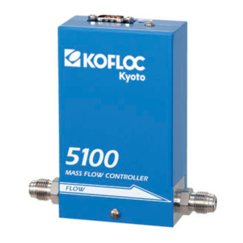
Electrical Test Instruments MAC-20 User manual

/,
It onitor AmmGter Gnntralter
MRG.2[T
Circuit Breaker Test Set
Retrofit Package
lnstruction Manual
itlarih tr, l9r,r9
Electrical Test Instruments' Irlc.
525 Old Westminster Pike
Suite M
Westminster, MD 21157
{410\ 816.4641
Fax: (41G) 848-0181

Electrical Test lnstruments MAC-20 Rekofit package
TABLE OF CONTENTS
SECTION l: GENERAL INFORMATTON and SpECtFtCATtONS
WARNING
About This Manual
Changes from Original Test Sets
Trademarks
lntroduction
General Description
Specifications
SECTION ll: DETAILED DEScRIPTtON
t-1
l-2
t-2
t-3
l-3
t-3
l4
Theory of Operation
High Current Test Sets
MAC-20 Hardware
MAC-20 Software
Retrofit lndicator Panel
Major Parts ldentification and Operation
MAC-20 Control Panel
MAC-20 lnternal Parts
Figure ll-1: Front Panel
Retrofit lndicator Panel
Figure ll-2: Retrofit lndicator Panel
SECTION lll: OPERATING INSTRUCTIONS
Pre-Test lnstallation and Setup
Basic Guidelines and Suggestions
Single Pole Molded Case Breakers
Multi-pole Molded Case Breakers
Low Voltage Power Breakers
Motor Overload Relays
Ratioing Current Transformers
SECTION lV: SERVICE INFORMATION AND DOCUMENTATION
Maintenance and Calibration of MAC-20
Parts List (MAC-20)
Parts List (Retrofit Panel)
Overall Schematic (MAC-20)
Overall Schematic (Retrofit Panel)
Warranty
Additional Schematics
[-1
il-1
n-2
lt-2
|-4
lt-7
lr-8
il-9
lt-9
il t-1
il t-3
|t-4
nt-7
ilt-10
nt-14
llt-16
tv-1
tv-3
tv-3
tv-4
tv-5
tv-6
END
Copyright (C) 1994-1998 Electrical Test lnslruments, lnc. All Rights Reserved

Eleclrical Test lnstruments MAC-20 Retrofit Package
Section I - General lnformation and Specifications
sEcTtoN I
GENERAL INFORMATION
Copyright(C) 1994-'1998 Electrical Test lnstruments, lnc. All Rights Reserved

Electrical Test lnstruments MAC-20 Retrofit Package
Section I - General Information and Specifications
sEcTtoN I
GENERAL INFORMATION
WARNING
WARNING - READ THIS ENTIRE MANUAL AND THOROUGHLY
FAMILIARIZE YOURSELF WITH THE UNIT OPEMTION PRIOR
TO CONNECTING THE UNIT TO A SOURCE OF POWER, HIGH
CURRENT TEST SETS ARE NORMALLY POWERED FROM
HIGH CAPACITY 208 VOLT TO 575 VOLT SERVICES, AND
IMPROPER CONNECTION OR OPERATION COULD CAUSE
DAMAGE TO THE TEST SET AND EQUIPMENT UNDER TEST,
AS WELL AS CREATE AN UNSAFE CONDITION FOR PERSONS
OPEMTING THE SET,
Electric€l Test lnstruments, lnc.
Page l-1
Copyright(C) 1 994-1 998 All Rights Reserved

Electrical Test lnstruments MAC-20 Retrofit Package
Section I - General lnformation and Specifications
ABOUT THIS MANUAL
This manual consists of completely new descriptive, operational, and technical informa-
tion, based on many years of experience in the design, manufacturing, and operation of
electrical protective device test equipment. lt is intended to provide useful, up-to-date
and complete information for safe and efficient operation of the test set.
CHANGES FROM ORIGINAL TEST SETS
Several changes have been made in the design of high current test sets since early
models such as the EIL BTS-50, many of which are important for safety and conven-
ience of operation. Some of these may have been incorporated with the modifications
associated with the upgrade to the MAC-20 metering and control system.
ln the case of some manually operated models, such as the BTS-50, the original control
panel may have been retained, but in most retrofits a new indicator/control panel has
been installed. ln either case, the control panel allows operation of the test set without
the MAC-20, if necessary. The control panel also provides test (output ON/OFF)
indicators, interlock indicators, and a power on indicator.
Test sets which are controlled by a microprocessor or computer, such as the EIL PS-
250 and PS-600, or the Phenix Technologies' HC-30 and HC-100, require the addition
of a special control panel. This replaces the functions of tap selection and vernier
adjustment with electromechanical components such as switches and relays, to reduce
complexity and enhance reliability.
The EIL BTS-50, BTS-30 and BTS-20 units used the old Duffers current meter for
current and time measurement. The newer BTS-500, BTS-300, and BTS-200 used the
improved Accu-Amp. Units manufactured by other companies used other instrumenta-
tion for this purpose.
ln all cases covered by this manual, the old current meter and timer have been
replaced with the MAC-20 microprocessor based measurement and control unit.
Electric€l Test lnstruments, lnc.
Page 12
Copyright(C)'1 994-'1 998 All Rights Reserved

Electrical Test lnstruments MAC-20 Retrofit Package
Section I - General lnformatton and Specifications
TRADEMARKS
1. "Duffers" refers to a device manufactured by Duffers Corporation
2. "Accu-Amp" is a trademark for a device originally made by EIL lnstrOments, lnc.
3. "SmartCore" is a trademark of ZWorld Engineering, Davis, CA.
INTRODUCTION
A high current test set, such as the EIL BTS-50, may consist of two pieces known as a
"control unit" and an "output unit", or these functions may be combined in a single
package. These two functions, when connected by external or internal power cables
and control cables, form a test system with high current, low voltage outputs used for
primary injection testing of direct acting low voltage circuit breakers. The MAC-20 has
replaced the old current metering system and timer, and also provides enhanced output
control functions.
GENERAL DESCRIPTION
The MAC-20 microprocessor-based measurement and control unit features digital
readout of current and time enhanced by digital signal processing. Pulse (memory)
mode provides fast and accurate automatic evaluation of output current pulses as short
as one half cycle.
The MAC-20 incorporates a precision A"/D converter and special firmware for true-RMS
continuous and pulse current reading with much greater accuracy. lt also utilizes a
sophisticated current sensing system for more reliable current latch mode operation
and better timing accuracy. An LED digital readout for current in four ranges from 1000
A to 100 KA reduces the chance of operator error. An integral autoranging timer with
LED readout provides four digits in seconds or cycles mode, with a resolution of 0.001
second or 0.5 cycle. A preset function allows you to set a maximum ON time in seconds
or cycles, for convenient'Jogging" of output to desired current. The entire metering and
control package is designed to be removed and replaced very easily, so that it may be
transported separately.
The complete retrofit package also includes wiring changes to the original unit to
accommodate the MAC-20, and may also require an additional or modified control panel
to accomplish tap changes and vernier control. The retrofit is designed to simplify the
basic control functions for reliability and ease of troubleshooting.
Elecirical Test lnstruments, lnc.
Page l-3
Copyright(C) 1 994-1 998 All Righls Reserved

Electrical Test lnstruments MAC-20 Retrofit Package
Section I - General lnformation and Specifications
MAC-20 Specifications
INPUT POWER:
120 VAC, SINGLE PHASE
50/60 HZ, 20 VA Max
CURRENT RANGES:
0-1,000 / 5,000 / 25,000 / 100,000 Amperes
CURRENT ACCURACY:
+^ 0.5% Reading + 0.5% Full Scale + 1 Digit (Continuous)
+/-'1.0% Reading + 1.0% Full Scale + 1 Digit (Pulse > 0.0'l sec)
TIMER RANGES:
0-9.999 / 0-99.99 / 0-999.9 / 0-9999 Seconds
0-999.9 / 0-9999 Cycles
TIMER ACCURACY:
+/- 0.005 sec +l 0.005% of reading +/- 1 count
DIMENSIONS AND NET WEIGHT
Height: 7.0 in. (178 mm)
Width: 19.0 in. (483 mm)
Depth: 6.0 in. (152 mm)
Weight: 10|b. (4.55 kg)
STANDARD ACCESSORIES
Power cable 1
Remote Control cable I
Electrical Test lnstruments, lnc.
Page l*4
Copyright(C) 1994-1998 All Rights Reserved

Electncal Test tnstruments MAC-20 Retrofit Package
Section lll - Detailed Description
sEcTtoN il
DETAILED DESCRIPTION
Copyright(C) 1994-'1998 Electricat Test lnstruments, tnc. Alt Rights Reserved

Electrical Test lnstruments MAC-20 Retrofit Package
Sectjon ll - Detailed Description
SECTION II
DETAILED DESCRIPTION
THEORY OF OPERATION
High Current Test Sets
High cunent test sets generally consist of the following:
1. One or more coarse taps accomplished by:
(a) A tapped autotransformer providing several equal steps of voltage or
(b) A multi-section output transformer
2. A continuously variable vernier adjustment between coarse taps by means of:
(a) A variable autotransformer and boost transformer, or
(b) A variable autotransformer connected to a section of the output trans-
former.
3. An output transformer with one or more isolated low voltage, high current sec-
ondary.
Power control circuitry consisting of switches, relays, protective devices, etc.
Current measurement circuitry consisting of sensors, current meter, and timer.
ln general, a primary voltage is selected by means of a combination of coarse tap and
vernier adjustment. This voltage is stepped down by the output transformer to provide
the desired current into the load impedance.
For test sets using an electromechanical contactor, an AC-controlled solid-state relay
with zero-crossing detection is often used to energize the main contactor. This provides
some consistency of output waveform, since the contactor will always pull in at some
fixed time after the zero crossing, and hopefully not at a multiple of a half-cycle. This
tends to minimize the DC offset which results when an inductive load is energized at or
near the voltage zero-crossing.
Many modern test sets use solid-state SCR controllers, with electronic circuitry to
provide precise phase control of initial firing angle. Solid state contactor replacement is
a retrofit option that is highly recommended.
MAC-20 Unit Circuitry
The current measurement function of most breaker test sets is based on the principle of
an air core inductor, which may be used to sense a magnetic field, which is proportional
to the rate of change of current flowing in an adjacent conductor. The output voltage of
the inductor is therefore proportional to the rate of change of current in the conductor.
For practical purposes, the sensing inductor is usually made in the form of a split core,
or "fork", which fits closely around the current-carrying buswork.
Electrical Test lnstruments, Inc.
Page ll-1
Copyright(C) 1994-1998 All Rights Reserved

trlectrcal I est lnstruments MAC-20 Retrofit Package
Section ll - Detailed Description
ln the measurement system, in this case the MAC-20, the signal from the current
sensor (typically about 50 mV for 1000 Amperes), is connected to an integrator,
consisting of precision resistors and a capacitor. This signal is processed by a variable-
gain instrumentation amplifier, and a digitally programmable gain circu-it. An analog to
digital converter (ADC), under microprocessor control, reads this signal to a precision of
'12 bits (+/- 0.025o/o). This circuitry is contained on a single PC board, originally devel-
oped for the Electrical Test lnstruments ORTMASTER system.
The heart of the MAC-20 consists of a microprocessor core unit, based on the Zilog
2180, with associated ROM, RAM, and other circuitry, and manufactured by ZWorld
Engineering under the trade name SmartCore. lt is connected to a motherboard, which
contains a regulated power supply, some support circuitry, and two programmable
peripheral interface (PPl) lC's. One PPI is configured as a Centronics parallel interface,
and controls the A/D subsystem described above. The other PPI interfaces to the
keyboard / display PC board, described below. Software contained in the ROM, (also
known as "firmware"), performs the required real{ime data collection, measurement,
user interface, and output control functions.
The keyboard / display PC board contains virtually all of the hardware for the user
interface (LED displays and keyboard), as well as contact sensing and output initiation
circuitry. The eight LED digits are multiplexed, and have limited alphanumeric capability
for more flexible indication of such conditions as overrange. The keys are scanned at
roughly 30 times per second, and incorporate LED's to indicate status. An audible
indicator (beeper) sounds when a key is pressed. The contact sensing circuit-
ry uses the key scanning system, with a transformer for isolation. The sensing signal is
a repetitive pulse of low voltage and low current, and contact sensing leads may be
handled without fear of shock. Two separate optically isolated signals are provided for
output initiation with an electromechanical contactor or SCR. All functions of the
keyboard / display PC board are handled by a single PPl.
MAC-20 Software
A complete description of the software is beyond the scope of this manual; however,
the following brief overview may enhance your understanding of the MAC-20. The
SmartCore is based on a Zilog 2180 processor running at 9.2'16 MHz. lts instructions,
written in C and assembly language, are contained in a socketed EPROM, and data is
stored in self-contained static RAM. The 21B0 contains a programmable reload timer
(PRT), which is set to provide an interrupt at a rate of 1200 per second. A watchdog
timer provides reset control and protection from software hangup conditions.
Much of the processing takes place in the interrupt service routine (lSR), which is
executed 1200 times per second. This ISR reads the A,/D converter, processes the
data, and determines the presence or absence of current. lt also functions as the main
timer for pulse time measurement, and determines the repetiiion rate of other proc-
esses. The multiplexing of the LED display, and the scanning of the keyboard, are also
Electrical Test lnstruments, lnc.
Page ll-2
Copyright(C) 1 994-1998 All Righls Reserved

Eleckical Test lnstruments MAC-20 Retrofit Package
Section ll - Detailed Descnption
handled by the lSR, but at slower rates of 300 times per second or less.
While not servicing the lSR, the software executes an idle loop, which updates
information to the display, and performs functions requested by new keystrokes.
Retrofi t lndicator Panel
The retrofit control panel replaces the original control panel, and performs the functions of
indicating POWER ON, OUTPUT ON, and INTERLOCK. lt also provides a REMOTE
INITIATE function to turn the output on without the MAC-20.
The POWER ON lamp is connected across the 120 VAC high and low circuits, and should
light whenever power is applied to the test set and the main power switch or circuit breaker is
turned on.
The OUTPUT ON lamp indicates that the SCR or contactor is energized.
The INTERLOCK lamp indicates that the interlock circuit is open. This may occur when an
interlock switch on an access door is open, the push-to-turn tap switch is engaged, the
interconnecting cable is not properly in place, or a thermal switch is open. The initiate circuit
is disabled by relay contacts.
The REMOTE INITIATE jack bypasses the initiate circuit of the MAC-20, and allows initiation
of the output by means of a dry contact closure between the tip and ring.
Copyright(C) 1 994-1 998 Electrical Test lnstruments, lnc. All Rights Reserved

Electrical Test lnstruments MAC-20 Retrofit Package
Section ll - Detailed Description
MAJOR PARTS IDENTIFICATION AND OPERATION
MAC-20 Control Panel
TIME DISPLAY: This 4 digit LED display normally indicates the elapsed time of a
current pulse. ln SECONDS mode, it displays time up to 9.999 seconds, then auto-
ranges to 99.99 seconds, 999.9 seconds, and 9999 seconds. ln CyCLES mode, it
reads time (based on 60 Hz), up to 999.9 cycles, then autoranges to 9999 cycles. lf
time exceeds maximum display capacity (10,000 seconds or 10,000 cycles), the display
will read "OVER". ln PRESET mode, the display indicates the maximum time of
initiation (oN time), in either cycles or seconds. A reading of zero disables the pRESET
function, and allows any time.
CURRENT DISPLAY: This 4 digit LED display indicates the output current. ln
CONTINUOUS mode, as well as in MEMORY mode before and during a test, the
display indicates true-RMS output current in real time, After completion of a test, in
MEMORY mode, the display shows the true-RMS value as computed over the entire
length of the pulse. This mode is indicated by a flashing LED on the MEMORY key. lf a
reading exceeds the maximum value for the selected range, the display will read
"ovER".
INITIATE key: This key is used to turn ON the output of the test set. The LED in the key
indicates that the MAC-20 is attempting to turn the output ON, but other conditions
(such as interlocks) could keep the output from actually turning on. ln MOMENTARy
mode, the key must be held to keep output current on; if LATCH is enabled, the output
will stay on until the breaker trips, or the STOP or RESET button are pressed. The
MAC-20 must be RESET in order to initiate output, and in N.C. or N.O. contact modes,
the contact status (continuity) must indicate that the breaker is closed. lf the output on
time exceeded the PRESET time, as indicated by flashing of the PRESET key LED, the
INITIATE key will automatically reset the MAC-20 and turn the output on.
STOP key: This key is used to turn the output of the test set OFF. lts LED indicates
that output is not being turned on by the MAC-20, but other conditions could cause
output voltage to be ON. Use of this key is usually necessary only when the LATCH is
enabied, and it is necessary to abort the test before the breaker trips. NOTE: lt is
important to realize that the interlock system of the circuit breaker test set may also turn
the output off, but it will turn back ON when the interlock condition is cleared.
RESET key: This key resets the displays on the MAC-20, and arms the pulse reading
system. The LED on the key indicates that the system is reset and armed. In version
1.4 and later, RESEI a/so takes the unit out of PRESET ADJUST mode, and turns
LATCH off.
PRINT key combination: On models equipped with a printer option, the STOP and
RESET keys may be pressed simultaneously to send the time and current readings in
Electrical Test lnstruments, lnc.
Page ll-4
Copyright(C) 1 994-1 998 All Rights Reserved

Electrical Test lnstruments MAC-20 Retrofit Package
Section ll - Detailed Description
ASCII format to a printer or other device.
LATCH key: This key toggles the LATCH mode for initiation; its LED indicates that this
mode is enabled. When in LATCH mode, the INITIATE key need only be pressed
briefly to turn output on. LATCH must be set in order to read pulse current when output
is initiated by means other than the MAC-20.
N.O. key: This key is used to set the Normally Open contacts mode. ln this mode, lack
of continuity on the CONTACTS binding posts indicates that the protective device under
test is in its normal (non{ripped) mode, and ready to accept current. This mode may
also be selected to use the MAC-20 as a manually operated timer. ln N.O. mode, ihe
timer starts as soon as the INITIATE key is pressed, and stops when released (if not in
LATCH mode), or when the STOP key is pressed or continuity is sensed at the
CONTACTS binding posts. Timing accuracy in this mode is typically +l- 0.01 seconds.
N.C. key: This key is used to set the Normally Closed contacts mode. ln this mode,
continuity on the CONTACTS binding posts indicates that the protective device under
test is in its normal (non-tripped) mode, and ready to accept current. This mode may be
used for testing multi-pole breakers by connecting the CONTACTS binding posts to an
unused pole. ln N.C. mode, the timer starts as soon as the INITIATE key is pressed,
and stops when released (if not in LATCH mode), or when the STOP key is pressed or
a break in continuity is sensed at the CONTACTS binding posts. Timing accuracy in this
mode is typically +/- 0.01 seconds.
C.L. key combination: When the N.O. and N.C. keys are pressed simultaneously, both
LEDs light, indicating C.L. mode (Cunent Latch). This is the normal power-up default
mode for the test set, and is recommended for all tests, unless there is a good reason
for using contacts to sense trip. ln this mode, current is continuously sampled, and
when it exceeds approximately 10% of the maximum current range value, the timer
starts, and calculation of pulse current begins. When current stops (or drops below a
dynamically determined threshold value), the timer stops running, and the final value for
pulse current is calculated and displayed. lf the output was initiated by the MAC-20, it is
turned OFF.
PRESET key: This key toggles the PRESET ADJUST mode, indicated by illumination
of its LED. When PRESET ADJUST is active, the adjacent SECONDS and CYCLES
keys respectively lower and raise the preset time in seconds or cycles, depending on
the timebase that was selected. Both keys may be pressed simultaneously to reset the
time limit to zero, which disables the time limit function. When not in PRESET mode,
the LED will flash if the displayed time exceeds the preset limit.
SECONDS key: This key normally selects the SECONDS timebase. lf the PRESET
mode is selected, this key is used to LOWER the preset time limit by 0.100 second
increments with the SECONDS timebase, or 0.5 cycle increments with the CYCLES
timebase. lf it is held, the reading will decrease at a rate of about 5 intervals per
second. lf a preset time limit was set in SECONDS mode, the output will be turned off
within several milliseconds after the limit has been reached. SECONDS or CYCLES
Electrical Test lnstruments. lnc.
Page ll-5
Copyright(C) 1 994-1998 All Rights Reserved

Electrical Test lnstruments MAC-20 Rekofit Package
Section ll - Detailed Description
timebase may be selected at any time before, during, or after a test.
CYCLES key: This key normally selects the CYCLES timebase. lf the PRESET mode
is selected, this key is used to RAISE the preset time limit by 0.100 second increments
with the SECONDS timebase, or by 0.5 cycle increments with the CYCLES timebase. lf
it is held, the reading will increase at a rate of about 5 intervals per second. lf a preset
time limit was set in CYCLES mode, the output will be turned off within several millisec-
onds after the limit has been reached. SECONDS or CYCLES timebase may be
selected at any time before, during, or after a test.
MEMORY key: This key toggles the MEMORY mode, indicated by illumination of its
LED. When in CONTINUOUS mode (LED off), the current display always reads the
real-time continuous output current of the test set. ln MEMORY mode (LED on), the
current display will read the continuous output current until the test is complete. At this
time. the LED will flash, and the display will read the computed true-RMS value of the
entire current pulse for the duration indicated on the TIME display. This key may be
pressed at any time before, during, or after the test, to toggle between the two modes.
1000 A range key: This key selects the 1000 ampere range, which provides best
accuracy of readings up to about 1000 amperes. Nominal currents close to this limit,
when applied to the device under test, will sometimes cause higher peak currents,
causing the display to read "OVER", indicating an overrange condition. lf this happens,
select the next higher range. Pressing any range switch will also RESET the MAC-20.
5 KA range key: This key selects the 5.000 KA range, for output currents up to about
5,000 amperes. See above for information common to all ranges.
25 KA range key: This key selects the 25.00 KA range, for output currents up to about
25,000 amperes. See above for information common to all ranges.
100 KA range key: This key selects the 100.0 KA range, for output currents up to
about 100,000 amperes. See above for information common to all ranges.
CONTINUIry lamp: This LED lights when continuity is detected at the CONTACTS
binding posts.
CONTACTS binding posts: These binding posts provide a low-power pulse signal
which detects continuity. A resistance of about 100 ohms or less will be interpreted as
continuity. Although the signal is low power and transformer isolated, it is good practice
to avoid touching any conductive surface connected to these terminals. CAUTION:
NEVER CONNECT THESE TERMINALS TO ANY LIVE CIRCUIT!
SERIAL port: On units with the printer option, this standard serial port may be con-
nected to a printer, computer, or other device to print or store time and current values of
test results in ASCII format.
Electrical Test lnstruments, lnc.
Page ll-6
Copyright(C) 1 994-1 998 All Rights Reserved

Electrical Test lnstruments MAC-20 Retrofit Package
Section ll - Detailed Description
MAC-20 lnternal Parts
INPUT CONNECTOR: This connector, located on the lower rear corner of the MAC-20,
provides 120 VAC control power, and connects to the air core CT (current sensor), and
initiate circuitry of the test set. The wiring of this connector is essentially compatible with
that of the EIL Accu-Amp, and ib designed to facilitate removal of the MAC-20 for
service or shipment.
ANALOG INTERFACE PC BOARD: This PC board, located near the input connector,
contains all of the MAC-20 analog circuitry. lt has two potentiometers for zero offset,
and one potentiometer for gain. lt also provides unregulated 10 VDC for the mother
board
MICROPROCESSOR MOTHER BOARD: This PC board, located adjacent to the
analog interface, contains a regulated power supply and support circuitry for the
microprocessor core module, and programmable peripheral interfaces for the analog
board and keyboard / display board. lt also supplies regulated 5 VDC for the keyboard /
display board.
MICROPROCESSOR CORE MODULE: This small PC board, manufactured by ZWorld
Engineering and called the SmartCore, contains a Zilog Z-180 microprocessor, crystal
controlled clock, support circuitry, static MM, and socketed program EPROM. lf
changes to firmware are required, the EPROM must be replaced. THIS SHOULD BE
DONE ONLY BY PERSONNEL EXPERIENCED IN HANDLING STATIC SENSITIVE
ELECTRONIC COMPONENTS.
KEYBOARD / DISPLAY BOARD: This large PC board, located on the front panel,
contains both LED displays and all keys used in the MAC-20. lt also contains an audible
beeper, and circuitry for the continuity light, contacts sensing, and output initiation. lt
connects to the motherboard with a 26 pin ribbon cable and a two conductor power
cable.
Electrical Test lnstruments, lnc.
Page ll-7
Copyright(C) 1 994-1 998 All Rights Reserved

Electrical Test lnstruments MAC-20 Retrofit Package
Section ll - Detailed Description
Figure ll-2: MAC-20 Front Panel
NE J, [:
HHr
H 5j
mEt
iFr
r-V-A
NEE
I cuRRENr I
m
.MMFHH
rffi;;fi-l
Monitor/Ammeter Controller
Model MAC-20
Electrical Test lnstruments, lnc
Page ll-8
Copyright(C) 1 994-1 998 All Rights Reserved

Electrical Test lnstruments MAC-20 Retrofit Package
Section ll - Detailed Description
Retrofit lndicator Panel
REMOTE lNlT jack: The remote initiate jack serves to control the output Independently
from the MAC-20. lt is a standard two-circuit phone jack. When TIP and RING are
connected together, the output will be initiated. The voltage and current in the control
circuit are approximately TTL logic level compatible.
POWER ON indicator: This amber neon lamp lights when power is applied to the test
set.
OUTPUT ON indicator: This red neon lamp lights when the SCR firing circuit is
energized, indicating that the output should be ON.
INTERLOCK ON indicator: This red neon lamp lights when one of the test set
interlccks are ON, which inhibits output initiation.
Figure ll-2 - Retrofit lndicator Panel
REMOTE
()
INITIATE
POWER
Orl
OUTPUT
ON
INTERLOCK
ON
Retrofit I ndicator Panel
Electric€l Test lnstruments, lnc.
Page ll-9
Copyright(C) 1 994-1998 All Rights Reserved

Eleclrical Tesl lnstruments MAC-20 Retrofit Package
Section lll - Operating lnstructions
sEcTtoN ilt
OPERATING INSTRUCTIONS
Copyright(C) 1994-'1998 Electrical Test lnstruments, lnc. All Rights Reserved

Electrical Test lnstruments MAC-20 Retrofit Package
Section lll - Operating lnstructions
SECTION III
OPERATING INSTRUCTIONS
PRE-TEST INSTALLATION AND SET-UP
1. The following components of the test set should be available and in good
condition:
a) Main Control Unit and Output Unit (if applicable).
b) MAC-20
c) Stab set to match breaker to be tested
d) lnput power plugs
e) lnput ground lead
f) lnterconnecting power cables (lf applicable)
g) lnterconnecting ground cable (lf applicable)
h) lnterconnecting control cable (lf applicable)
i) Contact lead set (lf applicable)
j) Remote initiate cable (optional)
a) Breakers to be tested
b) Manufacturers' curve data
c) Test log and/or report forms (See examples at end of section)
d) Basic hand tools (wrench, screwdriver, etc.)
e) Safety equipment (safety glasses, gloves, etc.)
f) Reliable and sufficient power source
g) Clean, spacious, and well-lit work area.
3. The MAC-20, which may be transported separately, must be installed as follows:
a) lnspect the interior of the Main Control Unit or Panel Fnclosure through the 19
inch opening.
b) Pull out the circular plug and fasten it to the mating connector on the MAC-20.
c) Carefully place the MAC-20 into the opening, and secure it by means of screws.
4. Calculate KVA requirements for the source per manufacturer's manual.
5. Locate a suitable earth ground, and connect it to the Main Control Unit with at
least #6 AWG wire.
Electrical Test lnstruments, lnc.
Page lll- 1
Copyright(C) 1 994-1 998 All Rights Reserved

Electrical Test lnstruments MAC-20 Retrofit Package
Section lll - Operating lnstructions
6. Ground the Main Control Unit to the Output Unit with the supplied ground cable
(lf applicable).
'' 7. Connect the two power cables between the Main Control Unit and the Output
Unlt, observing polarity (lf applicable).
8. Connect the interconnecting control cable between the Main Control Unit and the
Output Unit (lf applicable).
9. Make sure that the controls on the test set are adjusted as follows:
a) Main Power Switch (Circuit Breaker): OFF
b) Output Tap Switch: 1 (lowest tap)
c) Output Control Vernier: 0 (minimum position)
10. Remove rear access cover of Main Control Unit, (lf applicable), to be sure input
tap matches supply voltage. Replace panel. Failure to set input voltage tap properly
could cause a serious accidental overvoltage and DAMAGE TO TEST SET OR
INJURY TO OPERATOR COULD RESULT.
11. lf possible, TURN OFF power at source.
12. Connect power source to input of Main Control Unit, using connectors supplied.
13. lf Remote lnitiate Cable will be used, install NOW, before power is turned on.
14. Turn on power at source, if turned off in step 11 above.
15. Connect breaker under test to appropriate output tap, using stabs or cables as
required.
16. Make sure that breaker is CLOSED.
17. Turn Main Power Switch (Circuit Breaker) ON.
18. lf everything is OK, POWER ON and TRIP (or output OFF) lights will glow,
INTERLOCK indicators will be OFF, and the MAC-20 will perform its power on se-
quence.
19. Follow Step-by-Step procedures below, as required, for testing.
20. When tests are completed, turn TAP SWITCH to '1 , VERNIER to 0, and MAIN
POWER switch OFF.
21 . Turn off supply power, if possible, and disconnect input power cables.
22. Remove interconnecting power and control cables (lf applicable).
23. Remove interconnecting ground cable (lf applicable).
24. Remove ground cable from Main Control Unit to earth ground.
25. lf unit is to be transported, under rough conditions, remove MAC-20 and carry
seParatelY.
Copyright(C)'1994-1998 Electric€l Test lnstruments, lnc. All Rights Reserved
Page lll-2
Other manuals for MAC-20
1
Table of contents
Other Electrical Test Instruments Controllers manuals
