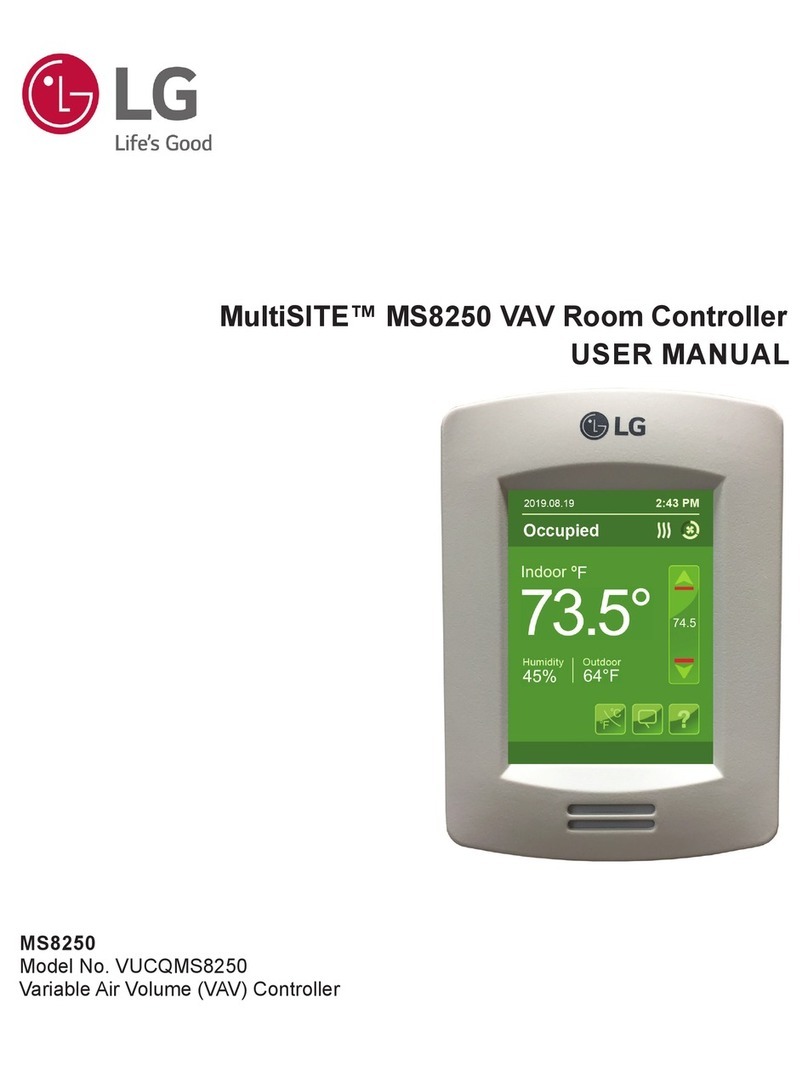
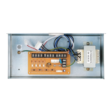
LG MultiSITE MS8250 User manual

MS8250
Model No. VUCQMS8250
Variable Air Volume (VAV) Controller
MultiSITE™ MS8250 VAV Room Controller
INSTALLATION MANUAL

The instructions included in this manual must be followed to prevent prod-
uct malfunction, property damage, injury, or death to the user or other
people. Incorrect operation due to ignoring any instructions will cause
harm or damage. A summary of safety precautions begins on page 4.
Do not throw away, destroy, or lose this manual.
Please read carefully and store in a safe place for future reference.
Content familiarity required for proper installation.
For more technical materials such as submittals, engineering
databooks, and catalogs, visit www.lghvac.com.
For continual product development, LG Electronics U.S.A., Inc., reserves the right to change specifications without notice.
©LG Electronics U.S.A., Inc.
This document, as well as all reports, illustrations, data, information, and other materials are the property of LG Electronics U.S.A., Inc.
PROPRIETARY DATA NOTICE
This document, as well as all reports, illustrations, data, information, and
other materials are the property of LG Electronics U.S.A., Inc., and are
disclosed by LG Electronics U.S.A., Inc., only in confidence.

3
Due to our policy of continuous product innovation, some specications may change without notication.
©LG Electronics U.S.A., Inc., Englewood Cliffs, NJ. All rights reserved. “LG” is a registered trademark of LG Corp.
Installation Manual
TABLE OF CONTENTS
Safety Precautions ......................................................................................................................................................................................................4-6
Before Beginning............................................................................................................................................................................................................ 7
Introduction..................................................................................................................................................................................................................... 8
Choosing a Location.................................................................................................................................................................................................9-10
Cleaning the Controller................................................................................................................................................................................................ 11
Installation..................................................................................................................................................................................................................... 12
Terminal Identication and Function.....................................................................................................................................................................13-18
Home Screen Display................................................................................................................................................................................................... 19
Set-Up Screen............................................................................................................................................................................................................... 20
Power Outage Clock Reset.......................................................................................................................................................................................... 21
Balancing .................................................................................................................................................................................................................21-25
Deployment Considerations........................................................................................................................................................................................ 26
PIR Sensor Details........................................................................................................................................................................................................ 27
PIR Energy Savings...................................................................................................................................................................................................... 28
Main Specications...................................................................................................................................................................................................... 29
Standards and Certications....................................................................................................................................................................................... 30

4
MultiSITE MS8250 VAV Room Controller
Due to our policy of continuous product innovation, some specications may change without notication.
©LG Electronics U.S.A., Inc., Englewood Cliffs, NJ. All rights reserved. “LG” is a registered trademark of LG Corp.
4
SAFETY PRECAUTIONS
TABLE OF SYMBOLS
DANGER
This symbol indicates an imminently hazardous situation which, if not avoided, will result in death or serious injury.
This symbol indicates a potentially hazardous situation which, if not avoided, could result in death or serious injury.
CAUTION
This symbol indicates a potentially hazardous situation which, if not avoided, may result in minor or moderate injury.
This symbol indicates situations that may result in equipment or property damage accidents only.
This symbol indicates an action that should not be performed.
The instructions below must be followed to prevent product malfunction, property damage, injury or death to the user or other people. Incor-
rect operation due to ignoring any instructions will cause harm or damage. The level of seriousness is classified by the symbols described
below.
Safety of personnel is the primary concern during all procedures. Read and understand this safety summary. Read and understand the instal-
lation procedure before beginning installation. Use the appropriate tools and accessories during installation. Plan the work and do not
work alone, if possible. Know how to obtain emergency medical and fire fighting assistance.
DANGER
Do not use or store ammable gas or combustibles near
the unit.
There is risk of re, explosion, and physical injury or death.
Disconnect power before installing or servicing the unit.
There is risk of physical injury or death due to electric shock.
Properly size all circuit breakers or fuses.
There is risk of re, electric shock, explosion, physical injury, or death.
Do not share the electrical circuit with other devices.
There is risk of re, electric shock, physical injury, or death due to heat
generation.
Do not use damaged or loose power wiring. Do not
modify or extend the power wiring randomly. Ensure that the
power wiring will not be pulled nor weight be placed on the
power wiring during operation.
There is risk of re, electric shock, and physical injury or death.
The information contained in this manual is intended for use
by an industry-qualied, experienced, trained electrician
familiar with local, national, and regional codes and who is
equipped with the proper tools and test instruments.
Failure to carefully read and follow all instructions will result in personal
injury or death.
All electric work must be performed by a licensed electrician
and conform to local building codes or, in the absence of lo-
cal codes, with the National Electrical Code, and the instruc-
tions given in this manual.
If the power source capacity is inadequate or the electric work is not
performed properly, it will result in re, electric shock, physical injury or
death.
Use copper conductors only. Refer to local, state, and federal
codes, and use power wires of sucient current capacity and
rating.
Wires that are too small will generate heat, cause a re and physical
injury or death.
Before making power terminations during earth grounding,
de-energize the power source. Do not restore power until
completing all other mounting and wiring.
There is risk of electric shock and physical injury or death.

5
Due to our policy of continuous product innovation, some specications may change without notication.
©LG Electronics U.S.A., Inc., Englewood Cliffs, NJ. All rights reserved. “LG” is a registered trademark of LG Corp.
Installation Manual
5
SAFETY PRECAUTIONS
Discharge yourself correctly before handling and installing
the controller.
There is risk of electric shock and physical injury or death.
Install in a controlled environment relatively free of contami-
nants.
There is risk of electric shock and physical injury or death.
Secure all eld wiring connections with appropriate wire
strain relief.
Improperly securing wires will create undue stress on equipment power
lugs. Inadequate connections will generate heat, cause a re and physi-
cal injury or death.
Ensure the system is connected to a power source that pro-
vides adequate power. Ensure that the wiring is the correct
size.
If the power source capacity is inadequate, the wiring is not the correct
size, or the electric work is not performed properly, it will result in short
circuiting, re, electric shock, physical injury or death.
Do not change the settings of the protection devices.
If the protection device is shorted and forced to operate improperly, or
parts other than those specied by LG are used, there is risk of re,
electric shock, explosion, and physical injury or death.
Properly tighten all power connections.
Loose wiring may overheat at connection points, causing a re, physical
injury or death.
Dispose of any packing materials safely.
• Packing materials, such as nails and other metal or wooden parts
will cause puncture wounds or other injuries.
• Tear apart and throw away plastic packaging bags so that children
may not play with them and risk suffocation and death.
Do not install the controller if it will be exposed to rain
or other precipitation. Do not install the unit in a location
exposed to open ame, extreme heat, or direct sunlight.
Do not touch the unit with wet hands.
There is risk of re, electric shock, physical injury, and/or death.
Use a soft, pre-moistened lint-free cloth for cleaning.
Avoid getting moisture in openings.
If moisture accesses the electrical components of the controller, there is
risk of re, electric shock, and physical injury or death.
Do not use caustic / corrosive products, ammonia, sol-
vents or any cleaning product containing alcohol or grit.
There is risk of re, electric shock, and physical injury or death.
Do not drop or crush the controller, or allow it to come
into contact with liquids.
There is risk of re, electric shock, and physical injury or death.
Do not spray anything directly on the controller or use
compressed air.
There is risk of re, electric shock, and physical injury or death.
Never use paint on the controller.
If moisture accesses the electrical components of the controller, there is
risk of re, electric shock, and physical injury or death.
Do not use a damaged device (such as one with a cracked
screen).
There is risk of re, electric shock, and physical injury or death.
Wear protective gloves when handling equipment.
Sharp edges cause personal injury.
CAUTION

6
MultiSITE MS8250 VAV Room Controller
Due to our policy of continuous product innovation, some specications may change without notication.
©LG Electronics U.S.A., Inc., Englewood Cliffs, NJ. All rights reserved. “LG” is a registered trademark of LG Corp.
6
SAFETY PRECAUTIONS
The information contained in this manual is intended for use
by an industry-qualied, experienced, trained electrician
familiar with local, national, and federal codes and who is
equipped with the proper tools and test instruments.
Failure to carefully read and follow all instructions will result in equip-
ment malfunction or equipment / property damage.
Ensure the system is connected to a power source that pro-
vides adequate power. Ensure that the wiring is the correct
size.
If the power source capacity is inadequate, the wiring is not the correct
size, or the electric work is not performed properly, it will result in control-
ler malfunction, miscommunication, and / or degraded performance.
Install the controller at least eight (8) inches away from in-
habitants, and do not locate near or operating in conjunc-
tion with any other antenna or transmitter.
There is risk of controller malfunction, miscommunication, and / or
degraded performance.
Disconnect power before installing or servicing the unit.
There is risk of equipment damage and degraded performance.
Clean up the site after all procedures are nished, and check
that no metal scraps, screws, or bits of wiring have been left
inside or surrounding the controller or indoor units.
Do not allow water, dirt, or animals to enter the controller.
There is risk of unit failure or degraded performance.
Do not spill water or other liquid on the inside of the con-
troller. Do not drop the controller into water. If the unit is
immersed in water or other liquid, contact your local autho-
rized LG distributor for support.
There is risk of unit failure or degraded performance.
This device is only intended for use as a monitoring and
control device. It is not a safety device. Do not use it for
any other purpose.
Tampering with the devices or unintended application of the devices will
result in a void of warranty. There also is risk of data loss or equipment
damage.
The controller is not compatible with a Power-Over-Ethernet
(POE) network. Do not connect the controller on a network
segment that carries power.
The unit may fail.
Use a soft, pre-moistened lint-free cloth for cleaning.
Avoid getting moisture in openings.
There is risk of equipment damage, and will void the manufacturer's
warranty.
Do not spray anything directly on the controller or use
compressed air.
There is risk of equipment damage, and it will void the manufacturer's
warranty.
Do not use caustic / corrosive products, ammonia, sol-
vents or any cleaning product containing alcohol or grit.
There is risk of equipment damage, and it will void the manufacturer's
warranty.
Never use tools directly on the touchscreen.
There is risk of damage to the controller screen, and it will void the
manufacturer's warranty.
Never use paint on the controller.
There is risk of equipment damage, and it will void the manufacturer's
warranty.
Do not drop or crush the controller, or allow it to come
into contact with liquids.
There is risk of equipment damage, and it will void the manufacturer's
warranty.
Do not use a damaged device (such as one with a cracked
screen).
Performance can be affected if the glass on the screen is broken, and it
will void the manufacturer's warranty.
7
Installation Manual
Due to our policy of continuous product innovation, some specifications may change without notification.
©LG Electronics U.S.A., Inc., Englewood Cliffs, NJ. All rights reserved. “LG Life’s Good” is a registered trademark of LG Corp.
Before Beginning
Loss of Control
• The designer of any control scheme must consider the potential failure modes of control paths and, for certain critical control functions,
provide a means to achieve a safe state during and after a path failure. Examples of critical control functions are emergency stop and over
travel stop. Failure to follow instructions will result in operation malfunction.
• Separate or redundant control paths must be provided for critical control functions. Failure to follow instructions will result in operation
malfunction.
• System control paths may include communication links. Consideration must be given to the implications of anticipated transmission delays
or failures of the link.1Failure to follow instructions will result in operation malfunction.
• Each implementation of equipment utilizing communication links must be individually and thoroughly tested for proper operation before be-
ing placed into service. Failure to follow instructions will result in operation malfunction.
1For additional information about anticipated transmission delays or failures of the link, refer to NEMA ICS 1.1 (latest edition), Safety Guidelines for
the Application, Installation, and Maintenance of Solid State Control or its equivalent.
California Proposition 65
This product can expose you to chemicals including Lead and Bisphenol A (BPA), which are known to the State of California to cause cancer and
birth defects or other reproductive harm. For more information, go to www.P65Warnings.ca.gov. Failure to follow these instructions can result in birth
defects or other reproductive harm.
Electrostatic Discharge / Static-Sensitive Components
Circuit boards and option cards can be damaged by static electricity. Observe the following precautions when handling static-sensitive components
such as controller circuit boards or testing components. Failure to follow these instructions can result in equipment damage.
• Keep static-producing material such as plastic, upholstery, and carpeting out of the immediate work area.
• Store static-sensitive components in protective packaging when these are not installed in the drive.
• When handling a static-sensitive component, wear a conductive wrist strap connected to the component or drive through a minimum of 1
megohm resistance.
• Avoid touching exposed conductors and components leads with skin or clothing.
BEFORE BEGINNING

8
MultiSITE MS8250 VAV Room Controller
Due to our policy of continuous product innovation, some specifications may change without notification.
©LG Electronics U.S.A., Inc., Englewood Cliffs, NJ. All rights reserved. “LG Life’s Good” is a registered trademark of LG Corp.
Introduction
This manual shows the installation instructions for the LG MultiSITE MS8250 Variable Air Volume (VAV) Room Controller (Firmware v2.4).
MS8250 Variable Air Volume (VAV) Room Controllers
For commercial and high end hospitality markets. The MS8250 is a low voltage variable air volume and zone Room Controller.
Features
• Low-voltage microprocessor-based VAV controller.
• Configurable to support damper control for Pressure Independent (PI) and Pressure Dependent (PD) VAV systems.
• Pre-programmed, containing all required I/O to accomplish VAV Application.
• Embedded local configuration utility using the touch screen allowing for simplified configuration, sequence selection, re-initialization, setting
of setpoints and control of display settings.
• Accurate temperature control using a Proportional-Integral (PI) algorithm.
• Integrated Changeover function.
• Configurable temporary or permanent local override setpoints.
• Local or remote override during unoccupied mode.
• Adjustable local unoccupied heating and cooling setpoint limits, as well as maximum heating and minimum cooling limits.
• Adjustable dead and proportional bands.
• Remote night set back.
• Door, window, wall, ceiling or motion detection.
• Custom programs using LUA Scripts.
INTRODUCTION

9
Installation Manual
Due to our policy of continuous product innovation, some specifications may change without notification.
©LG Electronics U.S.A., Inc., Englewood Cliffs, NJ. All rights reserved. “LG Life’s Good” is a registered trademark of LG Corp.
CHOOSING A LOCATION
A trained technician should always install the controller following local, national, and federal electrical codes; industry best
practices; the instructions in this manual; and using the proper tools and test instruments.
Failure to carefully read and follow all instructions will result in personal injury or death.
Discharge yourself correctly before handling and installing the controller.
There is risk of electric shock and physical injury or death.
Ensure the system is connected to a power source that provides adequate power. Ensure that the wiring is the correct size.
If the power source capacity is inadequate, the wiring is not the correct size, or the electric work is not performed properly, it will result in short circuit-
ing, re, electric shock, physical injury or death.
A trained technician should always install the controller following local, national, and federal electrical codes; industry best
practices; the instructions in this manual; and using the proper tools and test instruments.
Failure to carefully read and follow all instructions will result in equipment malfunction, controller and property damage, and will void the manufac-
turer's warranty.
This device is only intended for use as a monitoring and control device. It is not a safety device. Do not use it for any other
purpose.
Tampering with the devices or unintended application of the devices will result in a void of warranty. There also is risk of data loss or equipment dam-
age.
Ensure the system is connected to a power source that provides adequate power. Ensure that the wiring is the correct size.
If the power source capacity is inadequate, the wiring is not the correct size, or the electric work is not performed properly, it will result in controller
malfunction, miscommunication, and / or degraded performance.
Install the controller at least eight (8) inches away from inhabitants, and do not locate near or operating in conjunction with
any other antenna or transmitter.
There is risk of controller malfunction, miscommunication, and / or degraded performance.
Perform preventive maintenance on the damper and VAV box, according to manufacturer's instructions.
There is risk of product malfunction, miscommunication, and / or degraded performance.
Choosing a Location for the Controller

10
MultiSITE MS8250 VAV Room Controller
Due to our policy of continuous product innovation, some specifications may change without notification.
©LG Electronics U.S.A., Inc., Englewood Cliffs, NJ. All rights reserved. “LG Life’s Good” is a registered trademark of LG Corp.
A room temperature sensor is inside the controller, so the installation location is critical to proper system operation. Install the controller in a
location away from direct sunlight, high humidity, and direct flow or hot or cold air. Install the controller on a flat, clean wall surface approxi-
mately four to five (4 to 5) feet above the floor in an area with good circulation and average temperature.
Do's
• If replacing an existing controller, label wires before removing.
• Ensure the wall surface is flat and clean.
• Ensure the controller has sufficient, natural air circulation.
• Ensure the external thermal sensor wiring is away from electrical
sources.
• Install the controller four to five (4 to 5) feet (1.2 to 1.5m) above the
floor.
Do Not's
Do not install the controller:
• In drafts or dead spots behind doors and corners.
• In areas subjected to hot or cold air from ducts / air discharge grilles
• Near radiant heat from sun or appliances
• Near or with a direct heat source.
• In areas exposed to direct sunlight.
• Near concealed pipes or chimneys.
• Uncontrolled areas such as on an outside wall.
Failure to comply with these recommendations will result in damage to the unit and void the manufacturer’s warranty.
4 to 5 feet
above the floor
NO
YES
NO
NO
Figure 1: Controller Location.
Choosing a Location for the Controller, continued.
CHOOSING A LOCATION

11
Installation Manual
Due to our policy of continuous product innovation, some specifications may change without notification.
©LG Electronics U.S.A., Inc., Englewood Cliffs, NJ. All rights reserved. “LG Life’s Good” is a registered trademark of LG Corp.
CLEANING THE CONTROLLER
Use a soft, pre-moistened lint-free cloth for cleaning. Avoid getting moisture in openings.
There is risk of equipment damage, and will void the manufacturer's warranty.
Do not spray anything directly on the controller or use compressed air.
There is risk of equipment damage, and it will void the manufacturer's warranty.
Do not use caustic / corrosive products, ammonia, solvents or any cleaning product containing alcohol or grit.
There is risk of equipment damage, and it will void the manufacturer's warranty.
Never use tools directly on the touchscreen.
There is risk of damage to the controller screen, and it will void the manufacturer's warranty.
Never use paint on the controller.
There is risk of equipment damage, and it will void the manufacturer's warranty.
Do not drop or crush the controller, or allow it to come into contact with liquids.
There is risk of equipment damage, and it will void the manufacturer's warranty.
Do not use a damaged device (such as one with a cracked screen).
Performance can be affected if the glass on the screen is broken, and it will void the manufacturer's warranty.
Use a soft, pre-moistened lint-free cloth for cleaning. Avoid getting moisture in openings.
If moisture accesses the electrical components of the controller, there is risk of re, electric shock, and physical injury or death.
Do not spray anything directly on the controller or use compressed air.
There is risk of re, electric shock, and physical injury or death.
Do not use caustic / corrosive products, ammonia, solvents or any cleaning product containing alcohol or grit.
There is risk of re, electric shock, and physical injury or death.
Never use paint on the controller.
If moisture accesses the electrical components of the controller, there is risk of re, electric shock, and physical injury or death.
Do not drop or crush the controller, or allow it to come into contact with liquids.
There is risk of re, electric shock, and physical injury or death.
Do not use a damaged device (such as one with a cracked screen).
There is risk of re, electric shock, and physical injury or death.
Cleaning the Controller

12
MultiSITE MS8250 VAV Room Controller
Due to our policy of continuous product innovation, some specifications may change without notification.
©LG Electronics U.S.A., Inc., Englewood Cliffs, NJ. All rights reserved. “LG Life’s Good” is a registered trademark of LG Corp.
Figure 2: Open the Cover.
Figure 3: Install the Base.
Figure 4: Reinstall Cover
Installation
1. Remove security screw (if any) on bottom of Controller cover.
2. Open unit by pulling on bottom side of Controller (Figure 1).
3. Read FCC ID and IC label installed in cover before installing any wireless product.
4. Ensure correct side of base faces up.
5. Pull cables six (6) inches (15cm) out from wall.
6. Align base and mark location of two mounting holes on wall (Figure 2).
7. Install anchors in wall.
8. Insert cable in central hole of base.
9. Insert screws in mounting holes on each side of base.
10. Strip each wire 1/4 inches (0.6cm) from end.
11.Insert each wire and screw according to wiring chart (see following pages).
12. Gently push excess wiring back into hole.
13. Gently align cover to top of base and snap in place from bottom (Figure 3).
14. Install security screw.
INSTALLATION
Before making power terminations during earth grounding, de-energize the
power source. Do not restore power until completing all other mounting and
wiring.
There is risk of electric shock and physical injury or death.

13
Installation Manual
Due to our policy of continuous product innovation, some specifications may change without notification.
©LG Electronics U.S.A., Inc., Englewood Cliffs, NJ. All rights reserved. “LG Life’s Good” is a registered trademark of LG Corp.
Terminal Identification
Fan Type
Supported fan types:
• Parallel On / Off
• Serial On / Off
• Parallel Electronically Commutated Motor (ECM)
• Serial ECM
Supported output types:
• On / Off: Binary Output
• ECM: Analog Output
Table 1: Terminal Identication for Fan Control.
Binary (24 Vac)
Terminal Name Connection
4 BO4 24 Vac ~ Enable
6, 18 or 21 C / 24 Vac ~ Common 24 Vac ~ Common
ECM (0-10 Vdc)*
Terminal Name Connection
6, 18 or 21 C / 24 Vac ~ Common 24 Vac ~ Common
10 UO10 0-10 Vdc Output
*Floating duct reheat is not possible when fan type is ECM.
Air Flow Sensor (PI Only)
Supported air flow sensor parameters:
• Output voltage = 0-10 Vdc
• Pressure range = 0.5 or 5 inch water column
• Flow a one (1) inch water column:
• Minimum = 10
• Maximum = 10000
Table 2: Terminal Identication for Air Flow Sensors.
PI-Only Air Flow Sensor
Terminal Name Connection
5 RC / 24 Vac ~ Hot 24 Vac ~ Hot
6, 18 or 21 C / 24 Vac ~ Common 24 Vac ~ Common
24 UI24 0-10 Vdc Input
• Refer to the VAV box manufacturer flow chart for the recommended settings.
• See "Air Flow Sensor (PI Only)" above for recommendations.
TERMINAL IDENTIFICATION AND FUNCTION

14
MultiSITE MS8250 VAV Room Controller
Due to our policy of continuous product innovation, some specifications may change without notification.
©LG Electronics U.S.A., Inc., Englewood Cliffs, NJ. All rights reserved. “LG Life’s Good” is a registered trademark of LG Corp.
Damper
Supported output types:
• 0-10 Vdc Direct Acting
• 0-10 Vdc Reverse Acting
• 2-10 Vdc Direct Acting
• 2-10 Vdc Reverse Acting
• Floating
Recommended Damper Actuator Type: Elec, Prop, 0-10 Vdc, NSR, 24 Vac, Plenum, 35 in-lb or equivalent.
Table 3: Terminal Identication for Damper Actuator.
0-10 Vdc Analog Actuator
Terminal Name Connection
5 RC / 24 Vac ~ Hot 24 Vac ~ Hot
6, 18, or 21 C / 24 Vac ~ Common 24 Vac ~ Common
11 UO11 0-10 Vdc Output
Floating Actuator*
Terminal Name Connection
6, 18, or 21 C / 24 Vac ~ Common 24 Vac ~ Common
9 UO9 Close Actuator
11 UO11 Open Actuator
*Floating actuation time limits:
• Minimum = 0.5 minutes.
• Maximum = 9.0 minutes.
• Increment = 0.5 minutes.
Table 4: Terminal Identication for Changeover and Supply Sensors.
Changeover and Supply Sensors
Terminal Name Connection
19 UI19 Changeover Sensor
6, 18, or 21 C / 24 Vac ~ Common 24 Vac ~ Common
22 UI22 Supply Sensor
Changeover and Supply Sensors
The Room Controller is compatible with remote mount temperature sensors using 10K Type 2 NTC thermistors.
TERMINAL IDENTIFICATION AND FUNCTION

15
Installation Manual
Due to our policy of continuous product innovation, some specifications may change without notification.
©LG Electronics U.S.A., Inc., Englewood Cliffs, NJ. All rights reserved. “LG Life’s Good” is a registered trademark of LG Corp.
Table 5: Terminal Identication for Duct Heater.
0-10 Vdc Analog Duct Heater
Terminal Name Connection Required Settings
5 RC / 24 Vac ~ Hot 24 Vac ~ Hot Duct Heater Configuration:
• 0-10 Vdc Direct Acting, or
• 0-10 Vdc Reserve Acting
6, 18, or 21 C / 24 Vac ~ Common 24 Vac ~ Common
12 UO12 0-10 Vdc Output
Floating Duct Heater
Terminal Name Connection Required Settings
6, 18 or 21 C / 24 Vac ~ Common 24 Vac Common
Duct Heater Configuration: Floating10 UO10 24 Vac ~ Open Damper Actuator
12 UO12 24 Vac ~ Close Damper Actuator
On/Off or PWM Duct Heater
Terminal Name Connection Required Settings
6, 18 or 21 C / 24 Vac ~ Common 24 Vac ~ Common Duct Heater Configuration:
• On/Off, or
• PWM, or
• Valve NC, or
• Valve NO
12 UO12 24 Vac ~ Output
Table 6: Terminal Identication for Baseboard Reheat.
Relay with Transformer (Dry Contact)
Terminal Name Connection Required Settings
7 RH Room Controller Terminal 5 (24 Vac) Baseboard Reheat: Relay
8 BO8 24 Vac to Baseboard
24 Vac ~
Terminal Name Connection Required Settings
5 RC / 24 Vac ~ Hot Room Controller Terminal 7 (RH) Baseboard Reheat:
• Relay, or
• PWM, or
• Valve NC, or
• Valve NO
6, 18, or 21 C / 24 Vac ~ Common 24 Vac Common
7 RH Room Controller Terminal 5 (24 Vac)
8 BO8 24 Vac ~ to Baseboard
Reheat - Duct
Supported output types:
• 0-10 Vdc Direct Acting
• 0-10 Vdc Reverse Acting
• 2-10 Vdc Direct Acting
• 2-10 Vdc Reverse Acting
• Floating
• On/Off
• PWM
• Valve NC
• Valve NO
Reheat - Baseboard
The MS8250 controls baseboard heaters through:
• Relay = 4 CPH (Cycles Per Hour)
• PWM = 10-second duty cycle
• Valve (Normally Open or Normally Closed) = 8 CPH (Cycles Per Hour)
Supported output types:
• Relay On/Off
• PWM
• Valve NC
• Valve NO
TERMINAL IDENTIFICATION AND FUNCTION

16
MultiSITE MS8250 VAV Room Controller
Due to our policy of continuous product innovation, some specifications may change without notification.
©LG Electronics U.S.A., Inc., Englewood Cliffs, NJ. All rights reserved. “LG Life’s Good” is a registered trademark of LG Corp.
Pressure Independent (No Fan), 0-10 Vdc Analog Control
See the MS8250 Application Guide for more information on the “Sequence of Operations and Wiring".
Conguration Parameter Name Conguration Settings
VAV Box Type PI
Actuator Type 0-10 Vdc DA
Fan Type None
Reheat Configuration Duct + Baseboard
Duct Heater 0-10 Vdc DA
Baseboard Configuration PWM Vac
CHANGEOVER
SENSOR
Com.Sens.
SUPPLY AIR
TEMP. SENSOR
OPTIONAL
Com.Sens.
FLOW SENSOR
Com.RCOutput
13 14 15 16 17 18 19 20 21 22 23 24
BACnet +
BACnet -
BACnet REF
UI16
UI17
Common
UI19 - CS
UI20 - RS
C(Common)
UI22 - SS
UI23
UI24 - 0-10 Vdc Input
BO1
BO2
BO3
BO4 - Fan On
RC (24 Vac)
C (Common)
RH
BO8 - Aux Heat
UO9- Close Damp.
UO10 - Open Valve
UO11- 0-10 Vdc Output
UO12 - 0-10 Vdc Output
7 8 9 10 11 121 2 3 4 5 6
BASEBOARD 24 Vac
24 Vac Com.
0-10 Vdc ANALOG
HEATING COIL
Com.InputRC InputRC
0-10 Vdc ANALOG ACTUATOR
DAMPER
Com.
COMMON
24 Vac
FAN HI
FAN MED
FAN LO
Low-voltage
TERMINAL BLOCK
Figure 5: Pressure Independent (No Fan), 0-10 Vdc Analog Control Wiring Diagram.
Table 7: Pressure Independent (No Fan), 0-10 Vdc Analog Control Conguration Specications.
TERMINAL IDENTIFICATION AND FUNCTION
All electric work must be performed by a licensed electrician and conform to local building codes or, in the absence of local
codes, with the National Electrical Code, and the instructions given in this manual.
If the power source capacity is inadequate or the electric work is not performed properly, it may result in re, electric shock, physical injury or death.
BACnet®is a registered
trademark of ASHRAE.

17
Installation Manual
Due to our policy of continuous product innovation, some specifications may change without notification.
©LG Electronics U.S.A., Inc., Englewood Cliffs, NJ. All rights reserved. “LG Life’s Good” is a registered trademark of LG Corp.
Pressure Independent (Parallel Fan), 0-10 Vdc Analog Control
Conguration Parameter Name Conguration Settings
VAV Box Type PI
Actuator Type 0-10 Vdc DA
Fan Type Parallel Binary
Reheat Configuration Duct + Baseboard
Duct Hater 0-10 Vdc DA
Baseboard Configuration PWM Vac
BO1
BO2
BO3
BO4 - Fan On
RC (24 Vac)
C(Common)
RH
BO8 - Aux Heat
UO9- Close Damp.
UO10 - Open Valve
UO11 - 0-10 Vdc Output
UO12 - 0-10 Vdc Output
7 8 9 10 11 12
CHANGEOVER
SENSOR
Com.Sens.
SUPPLY AIR
TEMP. SENSOR
OPTIONAL
Com.Sens.
FLOW SENSOR
Com.RCOutput
13 14 15 16 17 18 19 20 21 22 23 24
BACnet +
BACnet -
BACnet REF
UI16
UI17
Common
UI19 - CS
UI20 - RS
C(Common)
UI22 - SS
UI23
UI24 - 0-10 Vdc Input
0-10 Vdc ANALOG
HEATING COIL BASEBOARD 24 Vac
24 Vac Com.Com.InputRC InputRC
0-10 Vdc ANALOG ACTUATOR
DAMPER
Com.
COMMON
24 Vac
FAN HI
FAN MED
FAN LO
Low-voltage
TERMINAL BLOCK
PARALLEL
FAN
Com.Enable
1 2 3 4 5 6
See the MS8250 Application Guide for more information on the “Sequence of Operations and Wiring".
Figure 6: Pressure Independent (Parallel Fan), 0-10 Vdc Analog Control Wiring Diagram.
Table 8: Pressure Independent (Parallel Fan), 0-10 Vdc Analog Conguration Specications.
TERMINAL IDENTIFICATION AND FUNCTION

18
MultiSITE MS8250 VAV Room Controller
Due to our policy of continuous product innovation, some specifications may change without notification.
©LG Electronics U.S.A., Inc., Englewood Cliffs, NJ. All rights reserved. “LG Life’s Good” is a registered trademark of LG Corp.
BO1
BO2
BO3
BO4
- Fan On
RC (24 Vac)
C (Common)
RH
BO8
- Aux Heat
UO9
- Close Damp.
UO10
- Open Valve
UO11
- Open Damp.
UO12
- Close Valve
7 8 9 10 11 12
CHANGEOVER
SENSOR
Com.Sens.
SUPPLY AIR
TEMP. SENSOR
OPTIONAL
Com.Sens.
COMMON
24 Vac
FAN HI
FAN MED
FAN LO
Low-voltage
TERMINAL BLOCK
13 14 15 16 17 18 19 20 21 22 23 24
BACnet
+
BACnet
-
BACnet REF
UI16
UI17
Common
UI19
- CS
UI20
- RS
C(Common)
UI22
- SS
UI23
UI24
- 0-10 Vdc Input
1 2 3 4 5 6
BASEBOARD 24 Vac
24 Vac Com.
HEATING VALVE
Com.OpenClose OpenClose
FLOATING ACTUATOR
DAMPER
Com.
Pressure Dependent (No Fan), Floating Control
Conguration Parameter Name Conguration Settings
VAV Box Type PD
Actuator Type Floating
Fan Type None
Reheat Configuration Duct + Baseboard
Duct Heater Floating
Baseboard Configuration Valve NC (Normally Closed)
TERMINAL IDENTIFICATION AND FUNCTION
Figure 7: Pressure Dependent (No Fan), Floating Control Wiring Diagram.
Table 9: Pressure Dependent (No Fan), Floating Control Conguration Specications.
See the MS8250 Application Guide for more information on the “Sequence of Operations and Wiring".

19
Installation Manual
Due to our policy of continuous product innovation, some specifications may change without notification.
©LG Electronics U.S.A., Inc., Englewood Cliffs, NJ. All rights reserved. “LG Life’s Good” is a registered trademark of LG Corp.
Time
Language (Select Preferred Language)
Unoccupied Mode Override
Date
Occupancy Status
Room Indoor
Temperature
Room Indoor
Humidity
Outdoor Temperature
Home Screen Display
User HMI is congurable and allows display functions such as Date, Time, Humidity, Outdoor Temperature, Setpoint, and others to be enabled or
disabled by setting various parameters.
HOME SCREEN DISPLAY
Figure 8: Home Screen Display with MS8250 Hospitality User Interface Shown.
Up Arrow
(Increase Temperature Setpoint)
Actual Setpoint
Down Arrow
(Decrease Temperature Setpoint)
Help (Enter Help Screen)
System Status

20
MultiSITE MS8250 VAV Room Controller
Due to our policy of continuous product innovation, some specifications may change without notification.
©LG Electronics U.S.A., Inc., Englewood Cliffs, NJ. All rights reserved. “LG Life’s Good” is a registered trademark of LG Corp.
1/2 Setup
Network
Configuration
Balancing
Setpoints
Display
Service View
Return to Home Screen
How to Enter the Set-up Screen
Figure 9: Entering the Set-up Screen.
• If a configuration/installer password is activated to prevent unauthorized access
to the configuration menu parameters, a password entry prompt shows to prevent
access to device configuration components.
• For more information on using and configuring the functions of the HMI, refer to
the LG MultiSITE MS8250 Series Room Controller User Manual.
Enter BACnet®and ZigBee®Network Settings
Enter Parameter Configuration Menu
Enter Balancing Settings
Enter Display Settings
Enter Setpoints Settings
Enter Status and Service View
SET-UP SCREEN
Figure 10: Set-up Screen Display.
Nonadjustable Parameter
Adjustable Parameter
Touch and hold this point for three
(3) seconds to enter set-up mode.
For more information on using and conguring the functions of the HMI, refer to the LG MultiSITE MS8250 Series Room Controller User Manual.
Other manuals for MultiSITE MS8250
1
This manual suits for next models
1
Table of contents
Other LG Controllers manuals

LG
LG PWFCKN000 User manual

LG
LG AC Smart 5 User manual

LG
LG MultiSITE MS8000 Series User manual

LG
LG GLOFA G3F - RD3A User manual

LG
LG Becon PREMTA000 Product guide

LG
LG G3F-TC4A User manual

LG
LG MultiSITE MS8000 Series User manual

LG
LG PRVC0 User manual

LG
LG LLLG003 User manual

LG
LG SV-iS5 Series User manual