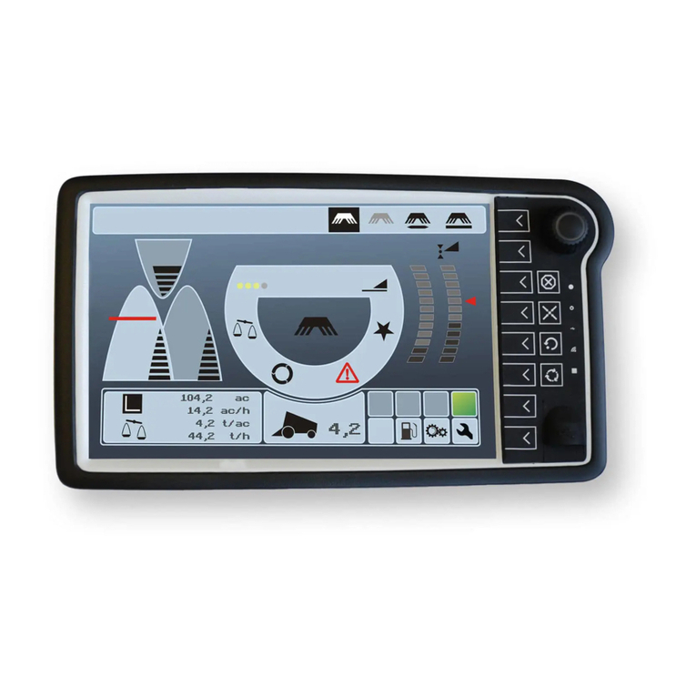
Topcon OPUS A3 Eco Specification sheet

1 / 9
Get started with OPUS devices v1.0
Contents
1Introduction.................................................................................................................2
2Get to know the device...............................................................................................3
2.1 Device types.........................................................................................................3
2.2 Keys on the devices .............................................................................................4
2.3 3D files for device integration ...............................................................................4
2.4 What cables / connectors are there?....................................................................5
2.5 Which pins are important?....................................................................................6
3Software.....................................................................................................................7
3.1 What software is installed on the device?.............................................................7
3.2 What software do I need to start?.........................................................................7
3.3 How can I connect to the serial console of the device?........................................7
3.4 How can I download my project to the device? ....................................................8
3.5 How can I change what is displayed when the device is powered on? ................8
3.6 Loading Screen ....................................................................................................9

2 / 9
1 Introduction
If you are reading this, you are very new to our OPUS devices. This document aims to
make your start a bit easier and to push you into the right direction.
This document will be less of a read-through text, but rather a collection of information
and tips that should speed up your learning process.
If you feel something is missing, please don’t hesitate to contact us.

3 / 9
2 Get to know the device
All relevant technical data and the standards that the device passed, can be viewed in
the technical datasheets available on our website.
2.1 Device types
The following device types are available now:
OPUS A3 Eco
OPUS A3 Standard
OPUS A6 Generation 2 Eco
OPUS A6 Generation 2 Standard

4 / 9
OPUS A8 Eco
OPUS A8 Standard
2.2 Keys on the devices
Most of the keys on Standard devices can be used freely in your programming environ-
ment:
Key
OPUS Projektor
CODESYS
C/C++/Qt
Soft keys
Free
Free
Free
Encoder
Free with limitations
Free
Free
Home
Pre-defined
Free
Free
Escape
Pre-defined
Free
Free
3 arrows key
Free
Free
Free
Stop Key
Free
Free
Free
Note that the Stop Key is only available on the OPUS A6 G2 and the OPUS A8.
2.3 3D files for device integration
To build the device into a dashboard, there are 3D step files available for all our devices.
Contact your vendor to receive them.

5 / 9
2.4 What cables / connectors are there?
All current devices have a 26-pin main connector with very similar pin out:
Pin No.
A3
A6 G1
A6 G2
A8
1
Power+
Power+
Power+
Power+
2
Ignition
Ignition
Ignition
Ignition
3
GND
GND
GND
GND
4
Car GND
Car GND
Car GND
Car GND
5
n.c.
n.c.
Audio_L
Audio_L
6
n.c.
n.c.
Audio_R
Audio_R
7
n.c.
n.c.
Audio_GND
Audio_GND
8
CAN 1 H
CAN 1 H
CAN 1 H
CAN 1 H
9
CAN 1 L
CAN 1 L
CAN 1 L
CAN 1 L
10
CAN 2 H
CAN 2 H
CAN 2 H
CAN 2 H
11
CAN 2 L
CAN 2 L
CAN 2 L
CAN 2 L
12
USB_VCC
USB_VCC
USB_VCC
USB_VCC
13
USB_GND
USB_GND
USB_GND
USB_GND
14
USB_D-
USB_D-
USB_D-
USB_D-
15
USB_D+
USB_D+
USB_D+
USB_D+
16
RS232 RxD
RS232 RxD
RS232 RxD
RS232 RxD
17
RS232 TxD
RS232 TxD
RS232 TxD
RS232 TxD
18
RS232 GND
RS232 GND
RS232 GND
RS232 GND
19
A/DI 3
A/DI 3
A/DI 3
A/DI 3
20
A/DI 1
A/DI 1
A/DI 1
A/DI 1
21
A/DI 2
A/DI 2
A/DI 2
A/DI 2
22
A/DI 4
A/DI 4
A/DI 4
A/DI 4
23
SERV_EN
SERV_EN
SERV_EN
SERV_EN
24
DO3
DO3
DO3
DO3
25
DO1
DO1
DO1
DO1
26
DO2
DO2
DO2
DO2
Note: Pins marked in green are not available on all variants of the devices.
For the main connector the following articles need to be used:
Connector housing, 26 pins –Tyco 3-1437290-7
Crimp Contact –Tyco 3-1447221-4
Blind Plugs –Tyco 4-1437284-3
This set can be ordered from Topcon Electronics, as well: OPSVF26001.
Additionally, some device variants have an Ethernet connector and 1 or 3 camera con-
nectors.
Video connector: Round Connector, 5 pins, M12
1 VidSig+
2 Mirror
3 Camera+
4 Camera -
5 VidSig GND

6 / 9
angled connector (90°) with cable
Escha WWASLW5P05 (can be ordered at Topcon Electronics, OPKAA3VID010)
Binder 79 4447 20 05
angled connector (90°) without cable
Escha WWASLW5K
Binder 99 1439 820 05
straight connector (0°) with cable
Escha WASLW5P05
Binder 79 4449 20 05
straight connector (0°) without cable
Escha WWASLW5K
Binder 99 1437 810 05
Ethernet connector: Round Connector, 4 pins, M12, acc. To IEC 61076-2-101
1 TD+
2 RD+
3 TD-
4 RD
angled connector (90°) without cable
Binder 99 3729 820 04
straight connector (0°) with cable
Binder 77 4529 0000 50704 0500
Phoenix 1403498 (can be ordered at Topcon Electronics, OPKAA3ETH010)
straight connector (0°) without cable
Binder 99 3729 810 04
2.5 Which pins are important?
Pins 1 to 4 are the most important one’s for operation. Please note that while the device
will start with only pins 1 to 3 connected, always connect pin 4, as well. Connect it to the
vehicle chassis if possible, otherwise connect with pin 3. Never leave pin 4 unconnected!
This will lead to problems with USB data transfers and other electrical problems.
When using your own cable, make sure that the USB cable is well shielded. An unshiel-
ded USB connection will lead to problems during USB data transfer.
The RS232 connection outputs the Linux system console by default, which can be a valu-
able tool in the development / debugging / testing phase, see chapter 3.3.

7 / 9
3 Software
3.1 What software is installed on the device?
Our OPUS devices run a Linux based operating system. On top of that runs either the
PClient, the runtime of the OPUS Projektor Tool, or the CODESYS runtime. Upon deliv-
ery, the chances are high that the versions of the device software are lower than what
you are working with. Make sure to update the devices to “your” software level.
3.2 What software do I need to start?
There are three ways to program our devices: The OPUS Projektor, CODESYS and na-
tive programming with C/C++/Qt.
Depending on the environment you are using, you need to install and configure the ap-
propriate IDE.
OPUS Projektor:
You should have gotten either a USB stick or a download for our developer package.
This package contains the Projektor installation file. Please note that you need the latest
64 bit Java for the Projektor to run. Once the program runs, you can find the files for the
devices in the menu Update -> OS / PClient update. First steps in the program are
described in the HTML manual (F1) in the chapter quickstart tutorial.
CODESYS:
To program with CODESYS, you need to download the IDE from 3S. You can download
it from here: https://store.codesys.com/codesys.html?___store=default
Pleas note that this links to the newest CODESYS version. The version our runtime cur-
rently has can be seen on the USB stick / in the downloaded zip file. E.g. if the version is
3.5.14.0, the right IDE version would be 3.5 SP 14. After installing the program, go to the
menu Tools -> Package Manager and install our package file (can be found under
\Customer Files\PC in the developer package). This loads the device description and
library files. The runtime and OS files are found under \Customer Files\Device\.
When starting a project, choose Standard Project and use ST code. Please note that
there is one device description for both A3 and A6 G1, and one for A6 G2 and A8.
All device functionality can be found under the Driver module. With Add Device you can
add modules for the functionalities you need to use. The modules are documented in a
Windows help file in the manuals folder of your CODESYS software package.
C/C++/Qt:
To program in C/C++/Qt, you need a linux environment with Qt installed. Check the chap-
ter Toolchain in the C++ developer guide found in the appropriate OS package. Please
note that we can’t give support for programming in C++ / Qt. For the devices you only
need to install the OS files found in the \images folder in the downloaded package.
3.3 How can I connect to the serial console of the device?
You need a terminal program that supports serial connections on your PC (e.g. Putty, Te-
raTerm, Hyperterminal). You also probably need an adapter from RS232 to USB to
connect the device to your PC. The following settings have to be made to connect to the

8 / 9
Linux system console:
- baud rate 115200
- 8 data bits
- 1 stop bit
- no parity
- no flow control
With these settings you are able to connect to the device. Please note, if you connect to
a running device, chances are that there is no output in the beginning. Press Enter to
check if the login prompt emerges. Use the following login data:
username: root
password:
- OPUS A3: opusa3
- OPUS A6 G1: opusa6
- OPUS A6 G2: egspro
- OPUS A8: egspro
The OS for A6 G2 and A8 is identical, hence the identical password.
You should find a document called console commands in the manuals folder of your soft-
ware package with an overview of interesting commands for testing and debugging.
3.4 How can I download my project to the device?
OPUS Projektor:
There are 3 ways: via USB, Ethernet or CAN. USB is the most straightforward. Open the
dialog through the menu Update -> Project Update. Then select the USB symbol. Put a
USB stick in the PC and change the directory to that of the USB stick. Then press Trans-
fer. After the process is finished, unplug the USB stick and plug it into the device while it
is running. The project should load and start automatically.
CODESYS:
The main way in CODESYS is through Ethernet. If you don’t have a device with Ethernet
port, you need to use an adapter USB <-> Ethernet. Several things need to be consi-
dered for this to work:
- same versions of CODESYS runtime and package on the PC
- set the IP on the device (see chapter 3.3): ifconfig eth0 192.168.135.6
- make sure your PC is in the same subnet as the device (e.g. 192.168.135.1)
- try if ping works from the PC to the device
3.5 How can I change what is displayed when the device is powered on?
The first image you see is called boot logo. This can easily be changed through your ap-
plication.
OPUS Projektor:
Create a project, open the project properties. In the General category you can load a
boot logo image. Make sure it has the resolution of the device. Load the project on the
display. Then restart and you should see the new boot logo.

9 / 9
CODESYS:
Create a project, right-click on Application, then add object, external file.
The image needs to be named logo.bmp. If you download the project to the device, the
logo will be changed. Restart the device and you should see the new boot logo.
3.6 Loading Screen
Between the boot logo and your application there can be a second screen.
OPUS PROJEKTOR:
The screen is called loading screen. You can also set it in the project properties in the
General category. This screen will be displayed while the project is loading. A black bar
will fill the whole screen from 10% to 90% horizontal resolution, so you can make parts of
your loading screen transparent to show a loading bar.
CODESYS:
right-click on Application, then add object, external file. The name and format of the
image depends on the device type. For A3 it needs to be rts_background.bmp. For A6
and A8 it needs to be background.png. Make sure the resolution of the image matches
the display resolution.
This manual suits for next models
5
Table of contents
Other Topcon Controllers manuals

Topcon
Topcon T18 User manual

Topcon
Topcon Athene SM-1 User manual

Topcon
Topcon Tesla User manual

Topcon
Topcon ASC-10 Installation manual

Topcon
Topcon Liquid Systems CM-40 User manual

Topcon
Topcon Wachendorff OPUS A8 ECO User manual

Topcon
Topcon ISOCAN User manual

Topcon
Topcon Norac UC5 User manual

Topcon
Topcon System 350 User manual

Topcon
Topcon X35 User manual