Electro-Air DM900UV-VO-WHT-VS User manual

OWNER’S MANUAL
MODEL DM900UV-VO-WHT-VS
WHOLE-HOUSE DUCT MOUNT HEPA AIR CLEANER WITH
ULTRAVIOLET LAMP & PHOTO CATALYTIC FILTER
IMPORTANT: PLEASE READ MANUAL BEFORE OPERATING UNIT
READ AND SAVE THESE INSTRUCTIONS
Features
Long-life, 99.97% HEPA (High Efficiency Particulate Air) Media Filter
removes particles 0.3 micron and larger
Carbon Prefilter removes lint and large particles, to extend life of HEPA Filter
Two High Output Ultraviolet Germicidal Lamps
CinQuartz™ Photo Catalytic Oxidation Filter removes unpleasant odors
and Volatile Organic Compounds
Carbon/ Potassium Permanganate Final Filter removes non-organic gases
Kills or inhibits bacteria, viruses, mold, fungi and microbial growth
Easy-to-change Filters and Lamps
Powerful motor delivers 250 CFM of clean, sterilized air
Heavy gauge galvanized steel cabinet and external powder-coat paint finish provides rigid
installation and durability
Plug-in Power Cord provides easy electrical connection
Versatile installation can be duct mounted, collar mounted or used as stand alone unit.
Stands with or without wheels optional
SAFETY CONSIDERATIONS
Read and follow instructions carefully. Follow all
local electrical codes during installation. All wiring
must conform to local and national electrical codes.
Improper wiring or installation may damage the Air
Cleaner.
Understand the signal words WARNING and
CAUTION which are present in the Owner’s
Manual. WARNING and CAUTION signify a
hazard which could result in property damage,
personal injury or death.
Only a heating/air conditioning installer or
qualified service person should install, repair,
or service your Whole-House HEPA, Ultraviolet
Light & Photo Catalytic Air Cleaner.
Homeowners or untrained personnel can
perform the basic maintenance functions of
replacing the filters or lamps.
When working on air cleaning equipment,
observe precautions in the Owner’s Manual,
labels attached to the unit, and other safety
precautions that may apply. Follow all safety
codes. Wear safety glasses and work gloves.
WHAT THE HEPA, ULTRAVIOLET LIGHT &
PHOTO CATALYTIC AIR CLEANER DOES
The Whole-House HEPA, Ultraviolet Light & Photo
Catalytic Air Cleaner has been designed to remove
particulate such as atmospheric and household
dust, coal dust, insecticide dust, mites, pollen, mold
spores, fungi, bacteria, viruses, pet dander, wood
smoke, cooking smoke and grease, tobacco smoke
and more.
The two non-ozone producing, high output
Ultraviolet lamps provide germicidal sterilization for
bacteria, viruses, mold and fungi and provide
photons to the CinQuartz™ Media (Photo Catalytic
Oxidation Filter) to reduce odors and Volatile
Organic Compounds (VOC’s).
A Final Filter containing a mixture of Carbon and
Potassium Permanganate further reduces odors,
light and non-organic gases.
BENEFITS
Helps provide relief from allergies, asthma, and
other respiratory illness.
Kills or inhibits bacteria, viruses, mold, fungi
and microbial growth.
Eliminates or reduces odors and gases emitted
from air fresheners, carpets, construction
materials, glues, household cleaners, paints,
varnishes, personal care products, press board
furniture and lots more.
Helps reduce housekeeping time and
redecorating costs.
Provides a healthier, more comfortable
environment, year-round.
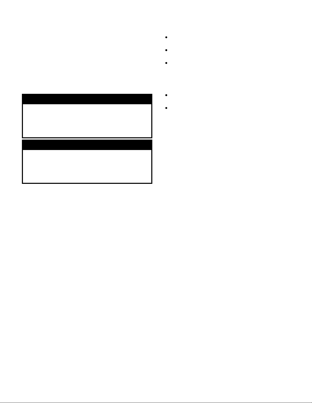
HOW IT WORKS
Millions of airborne pollutants are carried through
the return air ducts of the heating/cooling system.
The Air Cleaner has been designed to be installed
on the return air duct. A portion of this return air is
by-passed through an opening on the rear or top of
the unit and passes through a 5-stage filtration
system.
The air passes through a pleated Carbon Prefilter
to remove lint, large particles and heavy weight
gases to extend the life of the HEPA and PCO
filter.
Smaller particles then pass through a long-life,
99.97% HEPA (High Efficiency Particulate Air)
Media Filter which captures particles 0.3 micron
(1/84,000 of an inch) and larger. The filter becomes
more efficient as it gets dirtier with time. This HEPA
filter has more than 40 ft² of collection surface
area.
The clean air passes through a reflection chamber
where two High Output Ultraviolet (C band)
Germicidal Lamps emit powerful UVC light rays
which are designed to kill or inhibit bacteria,
viruses, mold, fungi and microbial growth. These
are non-ozone producing lamps. The Ultraviolet
Light is also used to activate the unique
CinQuartz™ Media located below the UVC lamps.
The CinQuartz™ Photo Catalytic Oxidation (PCO)
Filter is a Quartz media coated with nanoparticles
of Titanium Dioxide (TiO2). The combined action of
the UV light and the TiO2decomposes organic
materials into basic molecules such as H2O and
CO2and reduces odors and VOC’s as a result.
Air then passes through a Final Filter containing a
mixture of Carbon and Potassium Permanganate
further reducing odors and light gases.
Clean air is discharged back into the return air
duct.
WARNING
Before beginning any installation or modification, be
certain that the main line electrical disconnect switch
for the system is in the OFF position. Failure to do this
may cause electric shock or injury. Tag disconnect
switch with a suitable warning label.
WARNING
This unit is designed to emit powerful ultraviolet
radiation to sterilize microorganisms. It is dangerous to
come in contact with or look at the light from this unit.
Always turn the Air Cleaner OFF and UNPLUG the unit
before opening panels or the filter access door.
2
INSTALLATION
LOCATION
The HEPA Air Cleaner can be installed directly on
the return air duct eliminating the need for
external ducting. The unit can also be mounted on
the floor, a wall or be suspended from the ceiling
and with the use of collars, be ducted into the
return air plenum. Care should be taken to keep
the unit away from an area where there is a
possibility of moisture leaking on to it. Ensure
there is at least 15 inches in front of the unit to
allow removal of the filters and lamps.
GENERAL INSTALLATION STEPS
(Duct Mount) (see Fig. 1)
1. Before installing, remove any packaging.
Open the door and remove the filters.
Remove the lower panel on the front of the
unit to remove PCO and VOC filters and the
lamps and gloves which were packed at the
bottom of the unit. See Maintenance for
instructions to remove the filters.
2. If the unit is to be mounted on the return air
plenum, it must be installed after the last
return branch connection on the plenum. If
outside air is introduced into the return air
duct, either through a HRV (Heat Recovery
Ventilator) or direct, it should be added to the
system before the intake inlet to the Air
Cleaner.
3. Tape the mounting template level on the
plenum and proceed to cut and drill the
necessary holes as marked.
4. Remove the plastic film covering the back
holes and snip the small joints in the middle
of the mounting flaps on the back of the unit
as indicated on the template. Do not open
the holes on the top or bottom of the unit
if you are duct mounting the Air Cleaner.
Bend all the flaps outward slightly less than
90 degrees, except for the upper bottom flap
which is only bent up 45 degrees. This
bottom flap will act as a deflector for the
exhaust air entering back into the plenum.
5. Place the gasket material around the two
openings on the back of the air cleaner.
6. Place the unit on the plenum so the flanges
are placed through the holes cut in the duct.
Fold all the flanges, except the upper bottom
flap, over to enclose the duct between the
flanges and the unit. The upper bottom flap is
only bent up 45 degrees.
7. Secure the unit to the duct with the screws
provided.
WARNING
If you are installing this unit directly to the duct without
using collars, DO NOT open the top or bottom collar
mounting holes on the unit.
Fig. 1 –Duct Mount Installation
WARNING
When installing this unit directly to the return duct
insure there is no exposed plastic or wiring directly in
line with the exposed light from the lower mounting
hole on the back of the unit. The UVC light will cause
deterioration to plastic.
WARNING
This unit must be installed on the return air side of the
system only. Do not connect to supply side.
Do not install in a cooking area or connect directly to
any appliance.
CAUTION
This unit contains sharp edges. Always wear protective
gloves when handling the unit.
NOTICE
This unit has only been painted on the exterior. There
may be some over spray inside the galvanized steel
cabinet and this is normal.
3
CAUTION
This unit is not intended for use where there are high
levels of industrial chemicals present.

GENERAL INSTALLATION STEPS
(Collar Mount) (see Fig. 2)
(Inlet collars are available as a kit from your
distributor)
1. Before installing, remove any packaging. Open
the door and remove the filters. Remove the
lower panel on the front of the unit to remove
PCO and VOC filters and the lamps and gloves
which were packed at the bottom of the unit.
See Maintenance for instructions to remove the
filters.
2. This unit can be installed with collars and
aluminum flexible ducting if desired. DO NOT
use plastic duct. Openings are pre-punched
on the top and bottom of the unit for this
purpose. Remove the plastic film covering the
holes and snip out the joints to open the hole.
Do not open the holes on the back of the
unit if you are collar mounting the Air
Cleaner.
3. The collar is installed with the flange on the
inside of the cabinet with only the collar ring on
the outside of the cabinet. Compress the collar
until you can insert the flange into the opening
in the enclosure. Enlarge the collar to its
maximum and install two screws into the ring to
hold it to the proper diameter. Turn the collar in
the hole until the holes in the enclosure line up
to the holes on the collar flange. Secure with
the screws provided.
4. The intake collar on the return duct must be
installed after the last return branch connection
on the plenum. If outside air is introduced into
the return air duct, either through a HRV (Heat
Recovery Ventilator) or direct, it should be
added to the system before the intake inlet to
the Air Cleaner.
5. The 8 inch intake collar (top) must draw air from
the return duct at a location that will be ahead of
the clean exhaust air, that will be returned to the
duct from the Air Cleaner.
An 8 inch collar will be installed on the return
duct and a length of 8 inch flexible hose or duct
is required to attach between the 8 inch intake
collar and the collar on the return duct. When
running the hose, make sure that there are no
kinks or sharp bends that will impede the air
flow to the unit. Secure and seal the hose and
connections to prevent air leakage.
6. The 8 inch exhaust collar can be mounted in the
same manner to the bottom of the unit. An 8
inch collar will be installed on the return duct
close to the furnace and a length of 8 inch
flexible hose or duct is required to attach
between the exhaust collar and the collar on the
return duct. Do Not use plastic duct. The ideal
location is low on the return air boot pointing at
the furnace. To prevent air shear inside the
duct, it is recommended that you install a
deflector inside the boot, so the discharged air
is deflected down into the boot. When running
the hose, make sure that there are no kinks or
sharp bends that will impede the air flow from
the unit. Secure and seal the hose and
connections to prevent air and UV light leakage.
Fig. 2 –Collar Mount Installation
WARNING
If the top and bottom openings are being used to
install this Air Cleaner, ducting MUST be installed to
ensure no light escapes from the unit.
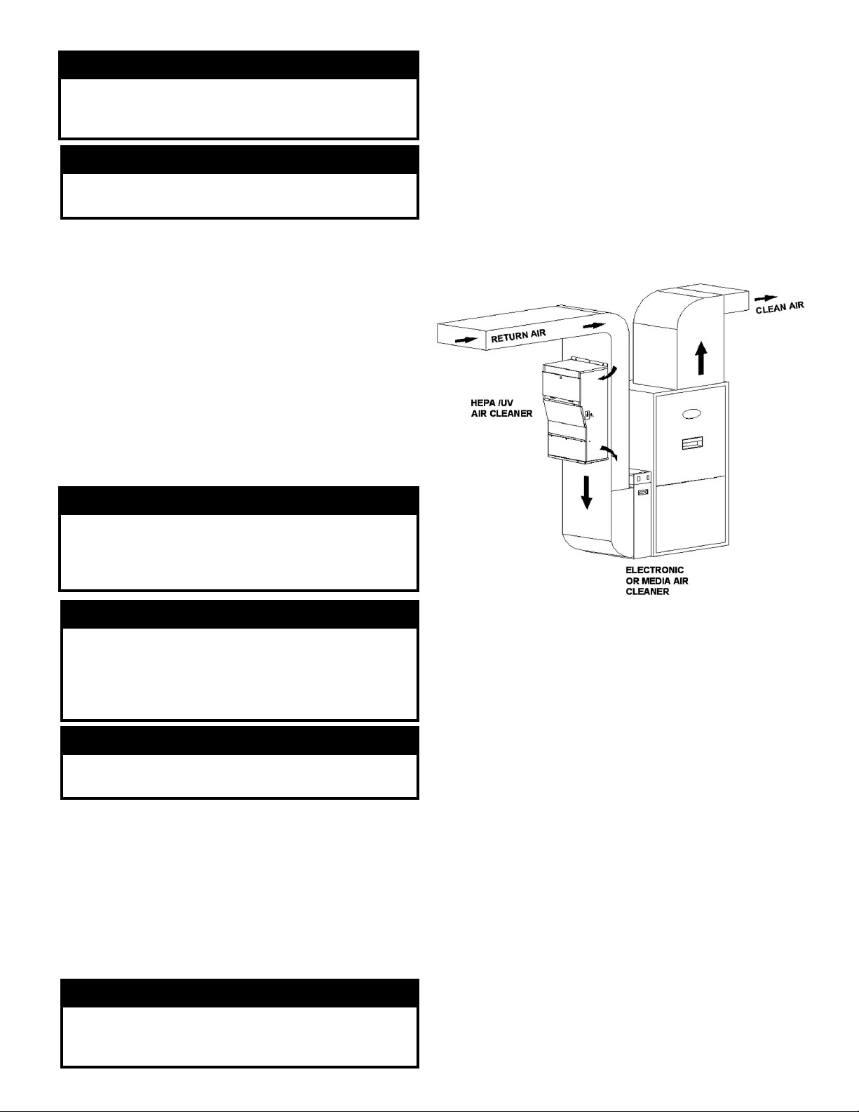
Fig. 3 –Self-Contained Basement Installation
Alternate Installations
4
AFTER INSTALLING AIR CLEANER
1. Install the two UVC lamps into the lamp holders.
Follow the instructions given in the maintenance
instructions. Use the cotton gloves provided
when handling the lamps. Replace the four
filters (see Fig. 5), close the filter access door
and replace the lamp access panel. Ensure all
the screws are in place and tight. Do not over
tighten.
2. After the installation, the unit must be checked
for sealing, both for air and light leakage. Any
leaks to the Air Cleaner must be sealed with
aluminum tape.
3. Turn the Air Cleaner ON and check for any
leaks of light. There must be no visible blue light
from the Air Cleaner. If you see any blue light
from the duct connections cover the holes with
aluminum tape.
OPERATING INSTRUCTIONS
The Air Cleaner is designed to run continuously to
provide clean, filtered air 24 hours a day. The fan
on the heating/cooling system, to which the Air
Cleaner is dependent on for circulated air, should
be on ‘continuous’ setting.
Running the Air Cleaner intermittently will
shorten the effective life of the lamps.
The Air Cleaner plugs into a regular 120 volt outlet
and is controlled by a switch located on the side of
the unit, near the cord.
Note: Do not allow the cord to be placed where it
may be walked on or allow anything to roll over it.
MAINTENANCE
For efficient operation, the filters must be changed
on a regular basis. If you notice a reduction in air
flow from the system, check the filters.
WARNING
Never use the Air Cleaner without all of the filters in
place and all cover panels and doors closed. Make
sure all the screws are in place.
CAUTION
Make sure to turn the Air Cleaner OFF before
performing any maintenance or removing any filters.
5
CAUTION
When the unit is new or after the lamps have been
replaced there may be a temporary odor. An odor may
also occur with high concentrations of chemicals in the
home such as paint or strong cleaning solutions. Both
odors are temporary and should dissipate within a
short time.
WARNING
Eye and skin damage may result from direct exposure
to the light produced by the lamps used in this product.
Make sure the Air Cleaner is OFF and UNPLUGGED
before the lamp access panel is open.
CAUTION
Do not touch the lamp glass with bare hands. Always
use the gloves provided when installing the lamps. The
oil from your hands may reduce the effectiveness of
the lamp. The lamp may be cleaned with a soft cloth
dampened with water to remove finger prints.
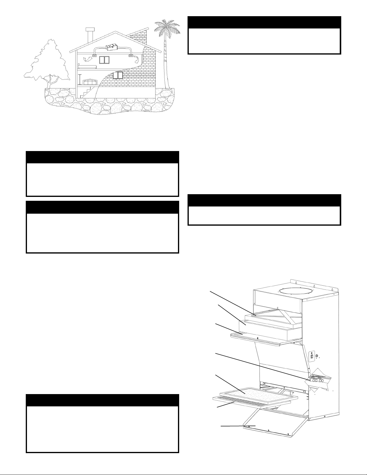
Fig. 4 –Self-Contained Attic Installation
Prefilter
HEPA Filter
Filter Access
Door
UVC Lamps
PCO Filter
Final Filter
Lamp Access
Removable
Panel
Fig. 5 –Air Cleaner Layout
1
2
3
4
Table of contents
Other Electro-Air Air Cleaner manuals

Electro-Air
Electro-Air 10C26S-010 User manual

Electro-Air
Electro-Air EAHEPA450 User manual

Electro-Air
Electro-Air EASA900VS User manual

Electro-Air
Electro-Air EAHEPA350 User manual

Electro-Air
Electro-Air MPRS1000 SOURCER Manual

Electro-Air
Electro-Air UST 16C26S-010 User manual

Electro-Air
Electro-Air EAHEPA550-3 User manual

Electro-Air
Electro-Air EAHEPA650 User manual

Electro-Air
Electro-Air EAP900 User manual

Electro-Air
Electro-Air EANC1620-A User manual


