Electro-Air SC-924A Manual
OPERATION & MAINTENANCE MANUAL
MODEL SC-924A
SELF-CONTAINED
ELECTRONIC AIR CLEANER
IMPORTANT: PLEASE READ MANUAL BEFORE OPERATING UNIT

Certified for shock and electrical fire hazard only.
INTRODUCTION
DESCRIPTION
The SC Series Electronic Air Cleaners are self-contained
units comprised of collecting cell(s), electrical
compartment, blower and motor assembly, complete
cabinet housing, prefilter(s) and after filter(s) or optional
carbon filter(s).
There are two sizes available:
Model SC-910: up to 1100 CFM capacity at 90%
efficiency
Model SC-924: up to 2100 CFM capacity at 90%
efficiency
The efficiency of the above units are rated on the removal
of particulate matter down to .01 micron including welding
fumes, automotive grinding dust, oil mist and carbon
black dust. On larger particulate matter such as .03
micron, it is possible for efficiencies to reach as high as
99%. This is based on the ASHRAE standard Dust Spot
Test.
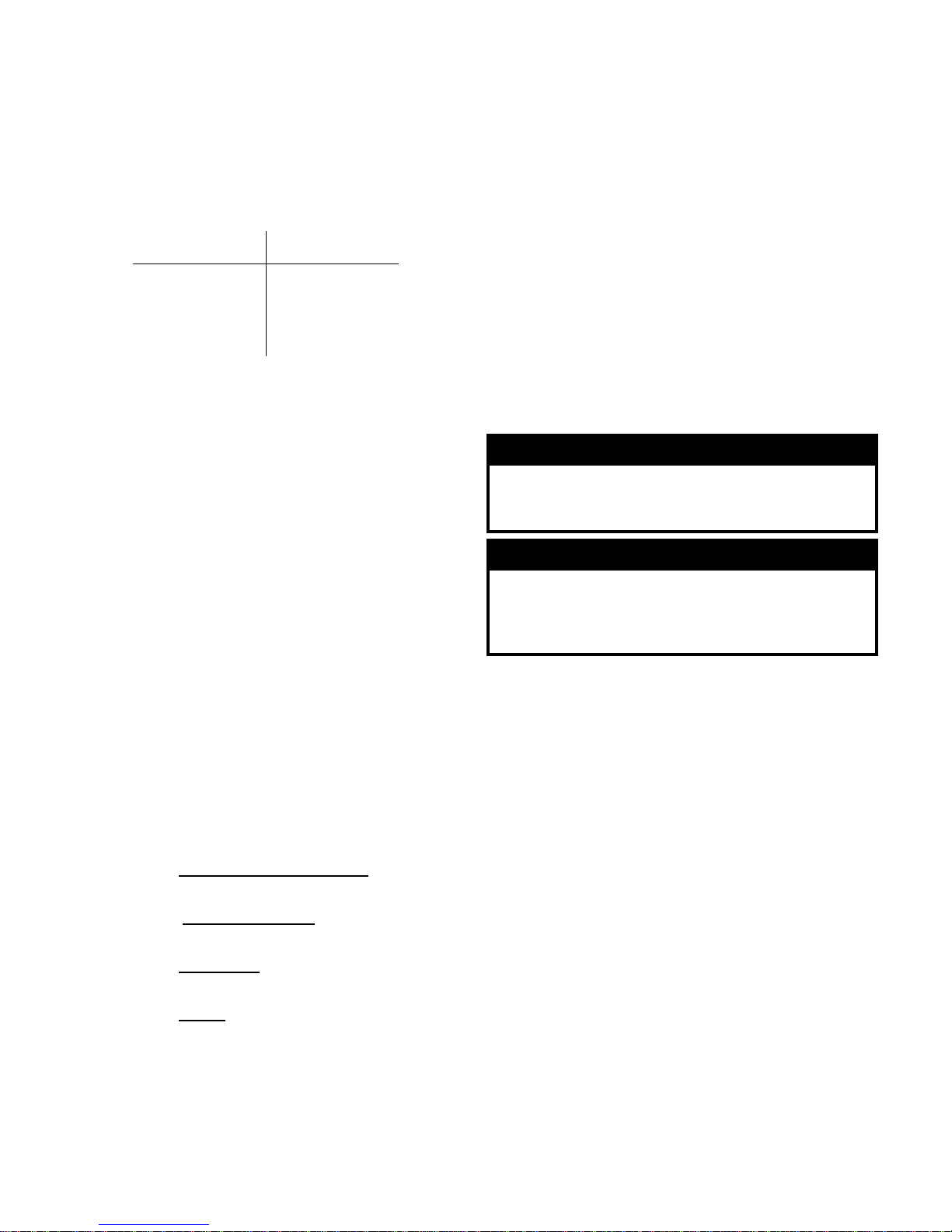
HOW IT WORKS
The Electronic Air Cleaner operates on the principle of
"Electrostatic Precipitation". Millions of airborne pollutants
are drawn in through the intake grill on the front of the air
cleaner and first pass through a prefilter where large
particles are caught. Next, smaller particles move to a
two-stage electrostatic collecting cell where they are
given a powerful positive charge by the ionizing wires.
Charged particles then move into the collecting area
where they are attracted to a series of alternately charged
and grounded plates. Pollutants are held on the plates
like a magnet until washed away during cleaning. Clean
air is then dispersed through the exhaust grill.
MAJOR COMPONENTS
CABINET
The cabinet is constructed of 18 gauge steel finished in a
scratch-resistant, electrostatic powder coated finish. The
unit has an interlocked cell access door, and two blower
access doors. The removeable intake grill is 20 gauge
expanded metal screen. Air is discharged through a 4-
way directional defuser. Weld nuts to accept 1/2 in.
threaded rods are incorporated into the cabinet top to
facilitate hanging the unit.
PREFILTERS
The washable prefilter measuring 16 x 20 in (40.6 x 50.8
cm) is constructed of multi-layers of aluminum mesh for
maximum filtration of large particles.
AFTER FILTER
The after filter measuring 16 x 20 in (40.6 x 50.8 cm) is
constructed of multi-layers of aluminum mesh for filtration
of agglomerated dust, and to maintain back pressure.
COLLECTING CELL
The two part collecting cell include support brackets,
collecting plates, support tubing, insulators, end plates,
spring contact, access handles, and separate ionizing
section; ionizing wires, ionizing wire support.
MOTOR & BLOWER
The motor is 3/4 HP TEFC, 1725 RPM. The blower is a
double inlet, centrifugal type with a forward inclined
wheel.
ELECTRICAL COMPARTMENT
The control panel on the front of the unit contains the two
lighted rocker switches to control the motor and power
board, and a performance indicator light, indicating high
voltage.
The high voltage power board is located in a separate
removable steel box mounted below the blower motor.
The power board is an open printed circuit board with an
adjustable output. The direct current output is 10,000
volts @ 3.5 mA. It is fused at 1.5 amps. A large value
resistor bank will bleed off the high voltage from the cell
when the unit has been turned off.
Quick disconnects on the board allow easy removal for
troubleshooting or repairs. The Performance Indicator
Light should be on during normal operation. The light
will flicker with arcing in the cell or extinguish if the cell,
ionizer or power board is shorted.
The cell access door is equipped with a safety interlock
switch to cut the power to the unit when the door is
Electrostatic Precipitation
2 Prefilter
1 Dirty Air
3 Ionizing Section
4 Collecting Cell Plates
6 Clean Air
5 After Filter or
Carbon Filter
(optional)
opened.
AIR VELOCITY
Air velocity is critical to operation of the unit and should
not exceed 500 FPM. Do not adjust drive to exceed this
velocity.
EXTERNAL STATIC
These units are not normally set up for ducting. Should
ducting be necessary, consult the factory regarding
blower and motor combinations.
SIZING AND LOCATION
The following are the general guidelines for sizing and
location of units.
GENERAL AIR CLEANING
Sizing of equipment is based on the recirculation of clean
air in the contained area. Determine the total cubic
footage of the area to be cleaned. Determine the number
of air changes that would be appropriate. This total is the
actual CFM necessary. Divide this figure by the capacity
of the SC unit that will be used and this determines the
number of units required.
Example: Body Shop
Desired air recirculation = 10 air changes/hr
Size of room (L x W x H) = 100 x 75 x 20 ft
Maximum CFM of SC-924 = 2100 CFM
L x W x H X Air Changes/Hour = Total CFM
60
Total CFM = No. of units
Maximum CFM of Air Cleaner
150,000 x 10 = 25,000 CFM
60
25,000 = 11.9 = 12 units
2,100
In the example above, 12 units should be placed so that a
uniform air flow pattern is developed. A good air flow will
ensure good cleaning.
MAINTENANCE SCHEDULE
The collecting cell,s ionizers, prefilters and after filters
must be cleaned on a regular basis for the unit to function
at its peak efficiency. The frequency of cleaning will vary
from one environment to another. For instance, in a
welding shop you may be required to wash the cell every
3 days to 2 weeks depending on the work load of the unit.
Every environment will be different. Inspect the unit
frequently until you determine the right washing schedule
for your particular application.
If your unit is equipped with an activated carbon filter it
will need to be refilled, depending on the environment,
every 3 - 6 months. Do not wash the carbon filter as this
will render it useless.
WASHING INSTRUCTIONS
1. Turn both the fan and power supply switches OFF
and wait 15 seconds for high voltage to dissipate.
2. Open the cell access door and remove the collecting
cells, ionizers, prefilters and after filters.
3. If the cell plates are heavily coated it may be
necessary to spray the cells with hot water to remove
the excess contaminate before applying detergent.
Allow excess water to drain off the cell before
applying detergent.
4. Place the cell and ionizer in a tub and spray
completely with DAX Detergent, allowing detergent
to run down both sides of the plates and ionizing fins.
Let sit for 5 minutes.
5. Rinse the cell well with hot water (140ºF / 60ºC
maximum).
6. If dirt remains on plates, let the cell soak in hot soapy
water for 30 minutes, then repeat the washing
instructions listed above. Never use any instrument
to clean the cell, as this may damage the ionizing
wires or cell plates.
7. An alternate method to clean the cell and ionizer is to
soak them in a tub of Dax for 10-15 minutes. The Dax
can be reused numerous times as long as the cell is
CAUTION
The cell plates are sharp. Handle with care. Take care
not to damage the cell by hitting the cell plates. The
cell plate spacing is critical for proper operation of the
unit.
CAUTION
Avoid washing the cell or ionizer with a high pressure
cleaner as this may cause damage to the cell plates
or fins.
SC-924
Intake Velocity 500 FPM
Discharge Velocity 2100 FPM
Internal Static .25 in WG
kept from sitting in the sludge which will collect in the
bottom of the tub. Never allow the cell or ionizer to
sit longer than 15 minutes in the DAX or they will
discolour. The tub should be covered when not in
use to prevent evaporation.
8. Spray the prefilter and after filter with DAX Detergent
and rinse well, applying water pressure against the
air flow direction. This pushes contaminate out of the
filter instead of forcing it through the filter..
9. To dry the cell and ionizer, tilt on a 45º angle against
wall with the direction arrow pointing sideways. Allow
to dry completely for at least 8 - 10 hours.
10. When the cells, ionizers, prefilters and after filters are
dry, install them back into the cabinet. The arrow on
the cell and ionizing section should point toward
the blower. The spring contact should line up
with the fibreboard on the back wall of the
cabinet. Close the door. If the cells arc when the fan
and power supply switches are turned on or if the
performance indicator light does not come on, then
the cells may still be wet. Allow more time for drying.
You can leave the cell and ionizer in the unit, turn the
fan switch ON and leave the power supply switch
turned OFF.
A cell placed in the air cleaner incorrectly can
burn out the power board.
11. The high voltage contact boards inside the cabinet
need to be cleaned on a regular basis to insure a
good contact with the cell and to prevent
accumulation of contaminate behind the contact
board. Clean the contact disc and surrounding red
contact board with a dry cloth while the accumulation
behind the contact can be removed with dry
compressed air. Complete access to the back of the
contact boards can be made from the outside of the
cabinet by removing the small panels on the back
side of the unit. The high voltage wires near the
contact boards should be wiped when the contacts
are cleaned and inspected annually by a qualified
service technician for deterioration.
12. The accumulated contaminate under the cells and in
the blower compartment should be removed at least
twice a year with a vacuum. Dry compressed air can
be used to remove the dust in the switch box and
power box which houses the high voltage power
supply. Do not apply air pressure too close to the
components as this may damage them. Build up of
contaminates on the blower wheel and housing can
also be cleaned with dry compressed air. The motor
should also be blown off with dry compressed air or
vacuumed, particularly around the cooling fan intake
at the back of the motor.
CLEANING AND SERVICE
The use of DAX Detergent is recommended for cleaning
as it is a heavy duty solution used expressly for removal
of accumulated pollutants on cell plates. If used as
directed, DAX will not harm aluminum or steel if used as
directed. Any problem arising out of the use of another
cleaning agent will void the warranty.
DAX Detergent is available in 1 gallon (4.5 L) and 4.4
gallon (20L) containers, as well as 45 gallon drums (205
L).
SERVICE MAINTENANCE
1. Determine if the air cleaner is performing properly by
seeing that:
• Fan switch is ON
• Power Supply switch is ON
• Performance indicator light is ON
2. The performance indicator light, when lit, shows that
the power board is functioning properly and should be
lit during normal operation. The light will flicker with
arcing in the cell or extinguish if the cell, ionizer or
power board is shorted.
3. If the performance indicator light fails to light, check
the cells to ensure they have been installed properly.
4. If the light still does not come on, remove the cells
and ionizers and close the door. Turn the unit on. If
the light now comes on inspect the cells or ionizers
for damage or water. Check the high voltage wires for
deterioration. Do not run the unit for more that 1
minute with the cell and ionizer removed. If the
light still is not on then the problem could be in the
light or the power board. Check the fuse on the power
board for continuity.
5. A simple test to ensure that the cell is in correctly and
there is high voltage to the cell is to take a long
plastic handle screwdriver and short the cell between
the frame of air cleaner and bolt head on the
porcelain insulators. Check both the cell and ionizer
for a spark. The fan and power supply switches
should be ON. Be sure to activate the safety interlock
switch before checking the voltage. CAUTION: You
are dealing with high voltage.
6. If in doubt and if cell is not collecting any carbon, tars
or body shop dust, then consult your dealer or factory
service center. The installing dealer should have
sufficient knowledge to determine any problems.
WARNING
Wear protective goggles, dust mask and gloves when
cleaning the inside of the cabinet. Always turn both the
fan and power supply switches OFF and turn OFF the
main breaker and lock out the unit before cleaning.


EA-924A-MAN.PUB
07/08
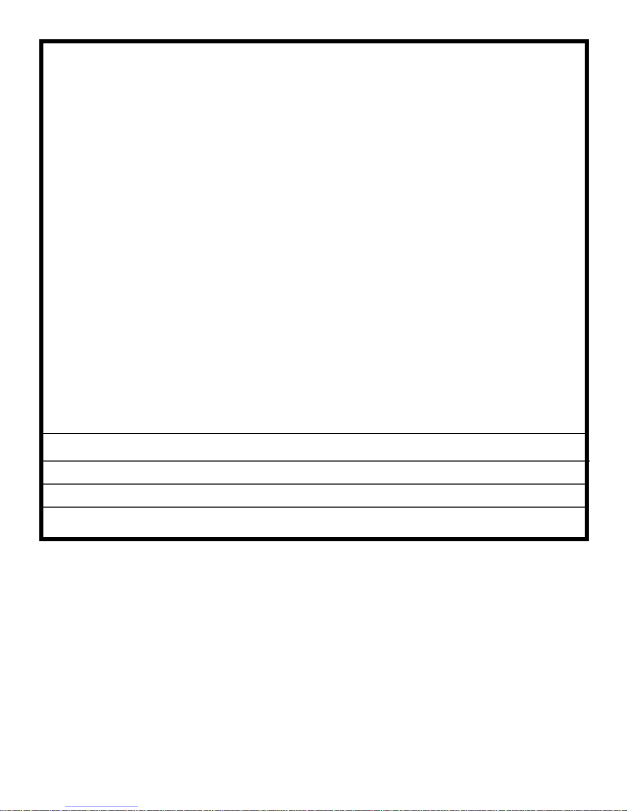
LIMITED ONE YEAR WARRANTY
Your Electronic Air Cleaner is guaranteed for one (1) year from the date of original purchase, against
electrical and mechanical defects in material and workmanship, under normal use and maintenance, which
will be repaired or replaced without charge, upon inspection by an authorized service center. The warranty
does not include the prefilter, after filter, carbon filter or ionizing wires.
This guarantee is in lieu of any other warranty, either expressed or implied.
ELECTRO-AIR CANADA will not be responsible for:
1. Normal maintenance as outlined in the Operation & Maintenance Manual including cleaning of electronic
collecting cells and/or replacement of carbon filters.
2. Damage or repairs required as a consequence of faulty installation or application by others.
3. Damage or repairs needed as a consequence of any misapplication, negligent handling, improper
servicing, unauthorized alteration, or improper operations.
4. Failure to start due to voltage conditions, blown fuses, open circuit breakers or other damages due to
the inadequacy or interruption of electrical service.
5. Damage as a result of floods, winds, fires, lightning, accidents, corrosive atmosphere, or other
conditions beyond the control of ELECTRO-AIR CANADA.
6. Parts not supplied or designated by ELECTRO-AIR CANADA.
7. ELECTRO-AIR CANADA products installed outside the continental Canada, U.S.A., Alaska, and Hawaii.
8. Any personal injury, special indirect or consequential property or commercial damage of any nature
whatsoever.
If warranty service is required, send the part(s) prepaid to your dealer or nearest authorized service center,
with a proof of purchase. Ensure that sufficient packing material is used. If part(s) arrive damaged due to
improper packaging, warranty will be void. Please enclose a note explaining the nature of your difficulty.
Model No. Serial No.
Date of Purchase Dealer Name
Owner’s Company Name & Address
RETAIN THIS CERTIFICATE WITH YOUR VALUABLE DOCUMENTS
Electro-Air Canada
351 North Rivermede Road
Concord, Ontario, Canada L4K 3N2
Toll Free: 1-800-267-8305
Phone: (416) 213-5636 Fax: (416) 213-5593
Email: info@fiveseasonsaircleaners.com
Table of contents
Other Electro-Air Air Cleaner manuals

Electro-Air
Electro-Air EAHEPA550-3 User manual

Electro-Air
Electro-Air EASASD-10ASC User manual

Electro-Air
Electro-Air MPRS1000 SOURCER Manual

Electro-Air
Electro-Air DM900UV-VO-WHT-VS User manual

Electro-Air
Electro-Air EAHEPA600M-3 User manual

Electro-Air
Electro-Air UST 16C26S-010 User manual

Electro-Air
Electro-Air EANC1620-A User manual

Electro-Air
Electro-Air 10C26S-010 User manual

Electro-Air
Electro-Air EAHEPA350 User manual

Electro-Air
Electro-Air EAP900 User manual


