Electronic Technologies ES3010 User manual
0

1
CONTENT
I. SafetyPrecautionsand Procedures.................................................2
II. Introduction.........................................................................................3
III Measuring Rangeand Accuracy...................................................4
IV TechnicalSpecifications.................................................................5
VTester Structure................................................................................7
VI Measuring Principle........................................................................7
VII. FunctionQuickCheck ....................................................................8
VIII. Operation Methods ........................................................................9
1Switch On/Off.............................................................................9
2Battery Voltage Check.................................................................9
3. Ground voltage measurement.......................................................9
4Wire Resistance Verification.....................................................10
5Grounding Resistance Precision Measurement.........................10
6Simple Method forMeasuring Ground Resistance...................11
7BacklightControl......................................................................12
8AlarmSettings.........................................................................13
9Data Lock/Storage.....................................................................13
10 DataReview/Deletion.............................................................13
IX. BatteryReplacement.....................................................................14
XAccessories....................................................................................14

2
I.SafetyRules and Precautions
Thanksforyourpurchaseof DigitalEarthResistance Tester
ofourcompany.Beforeyou usethe instrumentforthe firsttime,in
ordertoavoidpossibleelectricshockorpersonalinjury,please be
sureto: readand strictlyobservethesafetyrules and
precautionslistedinthismanual.
Underanycircumstance,itshall payspecialattentionon
safetyinuse ofthistester
uThe tester isconforming toIEC61010on design, production
and test.
uUnderanycircumstance,itshall payspecialattentionon
safetyinuse ofthistester.
uPlease don tuse high-frequencysignalgeneratorslike mobile
phoneand etc. toavoiderror during measuring.
uPayattention towords andsymbolsstickon the Tester.
uIt shall makesurethattesterand accessories areingood
conditionbeforeuse;itcan be usedonlywhen thereisno
damaged,naked orbroken part intestingwires orinsulation
layer.
uDuring measurement, itisforbidden totouch bareconductors
and circuit undermeasurement.
uConfirmthatconnectorplug ofleadhas been inserted inthe
tester interface closely.
uPlease don timpose over600VA.C.orD.C.voltage on the
part between testingend and interface.Otherwise,itmayhave
damageon the tester.
uPleasedon tmeasureinan inflammableplace.The flame
sparklemaybe cause explosion.

3
uDuring usage oftester,please stop usingitwhenexposed
metaliscaused bybroken enclosureor testing wires.
uPlease don tkeep orstorethe testerinthe spotwith
high-temperatureandmoisture,orcondensation,and under
direct daylight radiation for along time.
uForreplacing battery,please confirmtestingwirehas moved
apart the meter,and FUNCTIONSWITCHrotaryswitch isin
“OFF”position.
uPlease put the used batteries inappointed collectionplace.
uWhenreplacingthe batterywiththe meter,make surethatthe
testlinehas been removed fromthe meterand the meteris
turned off.
uWhenthemeterdisplaysbatterylowvoltage symbol“”,
and need toreplace the batteryintime.
uPayattentiontomeasuring range and usageenvironment
stipulated for the Tester.
uThismeasuring deviceisonlytobe used,disassembled,
adjusted and repairedbyqualified personnelwithauthorization.
uWhenitmaycause hazardbycontinuoususe forthe reason
ofthe Testeritself,itshallimmediatelystop usingitand depositit
at once, leaving it for disposalbyauthorized agency.
uForriskofdangericon inmanual ,usersmustperform
safetyoperationsstrictlyincompliance withthemanualcontent.
II.Introduction
Digitalgrounding resistance tester,alsoknownas the
three-wiregrounding resistance tester, grounding resistance
meter,etc., isacommonlyused meterformeasuring grounding
resistance.It adoptsalarge LCDgray-whitescreen backlight

4
displayandmicroprocessortechnologytomeettherequirements
oftwo-wireand three-wiretestresistance. Suitablefor
telecommunications,electricity,meteorology,computer
rooms,oil fields,powerdistributionlines,iron tower
transmission lines,gas stations,factorygrounding networks,
lightningrodsandsoon.Instrumenttestingisprecise,fast,
simple, stableandreliable.
The digitalgrounding resistance tester iscontrolled bythe
microprocessorand can automaticallydetectthe connection status
ofeach interface and the interference voltageandinterference
frequencyofthe ground network,and has the function oftesting
the auxiliarygroundingresistance value.Atthe sametimestore
500 setsofdata, resistance measurementrange:0.01 ~3000
, groundingvoltagerange:0.01~ 600.0V
III.Measuring Rangeand Accuracy
Measuring
Functions Measuring
Range Accuracy Resolution
EarthGround
Resistance
0.01Ω~30Ω±1.5%rdg±5dgt
(Auxiliaryearth
ground
resistance
100Ω±5%,
voltage toground
<10V)
0.01Ω
30.1Ω~300Ω0.1Ω
301Ω~3000Ω1Ω
EarthGround
Voltage
0.01~10.00V
AC ±1.5%rdg±3dgt 0.01V
10.1~100.0V 0.1V
101~600V 1V
(Remark:23℃±5℃,below75%rh)
5
IV.TechnicalSpecifications
Earthing
Resistance
Range 0.01Ω~3000ΩAccuracy±1.5%rdg±5dgt
Ground
resistance
resolution 0.01Ω
Grounding
voltage range 0.01~600VAC Accuracy±1.5%rdg±3dgt
Ground voltage
resolution 0.01V
Reference
conditions 23°C±5°C, 75% rhorless(Auxiliaryearth
resistance100Ω±5%, voltagetoground<10V)
Function Earthgroundresistancemeasurement, voltage to
groundmeasurement, lowvalue resistance
measurement
PowerSupply
DC 6V 1.5V LR14 battery
Backlight Controllablegrayscreenbacklight,suitable forusein
dimplaces
Measuring
Mode Precise3-pole measurement,simple2-pole
measurement
Measuring
Method
Earthgroundresistance:ratedcurrentchange-pole
method,Testcurrent >20mA(sine wave),128Hz;
Voltage toground:average value rectification
WireResistance
Verification
Avoid errorcausedbytestingwirethatisfailed tobe
fullyinsertedintotester interfaceor bypoorcontact or
byusers replacingorlengthening testingwires,
makingitmoreaccurateforearthgroundresistance
measurement.
DisplayMode 4-digitalsuper-large LCD display,grayscreen
backlight
Measuring
indicator Duringmeasurement,LED flashindicator,LCD count
downdisplay
LCD Dimension
108mm×65mm
Dimension L×W×H: 240mm×188mm×85mm
Testing Wires Three wires:eachforRed 15m,Yellow10m,and
Green 5m
SimpleTesting
Wire 2wires: eachfor Red 1.5mandGreen 1.5m
Auxiliary
2PCS

6
earthing rod
Measuring Rate
Voltage toground:about3times/second;earth
groundresistance: about5seconds/time
Measuring
Times Over 5000 times
Circuit Voltage Measuring voltage toground: measuring belowAC
600V
DataStorage 500 sets,flashdisplay “FULL”icon toindicatestorage
is full
DataRead Datareadfunction: “MR”icon display
Overflow
Display Exceedingmeasuring range overflowfunction: “
OL
”
icondisplay
AlarmFunction
Whenmeasuringvalueexceedsalarmsetting value,
thereis beeper alarming
BatteryVoltage
Batterypower indicateinreal time,thebatteryvoltage
is lowand remindtocharge intime
Power
Consumption
Backlight:25mAMax
Standby: 25mAMax(Backlightshutoff)
Measurement:70mAMax(Backlightshut off)
Weight
Tester:1230g (including battery)
TestingWires:610g (includingsimplytesting wires)
Auxiliaryearthingrod:360g(2PCS)
Meter bag:1200g
Working
Temperature&
Humidity -10℃~40℃;below80%rh
Storage
temperature&
humidity -20℃~60℃;below70%rh
Overload
Protection Measuring earthgroundresistance:betweeneach
interfacesof E-P、E-C,AC 280V/3seconds
Insulation
Resistance Over 10MΩ(between circuitandenclosureit is500V)
Withstanding
Voltage AC 3700V/rms (Between circuit and enclosure)
Electromagnetic
Features IEC61010-4-3,radio frequency electromagneticfield
≤1V/m

7
Protection Type
IEC61010-1 、IEC1010-2-31 、IEC61557-1,5 、
IEC60529(IP54)、Pollutiongrade 2、CAT Ⅲ300V
V.TesterStructure
1. MEMButton 2. ALARMButton 3. BACKLIGHTButton
4. LCD 5.TESTButton6.SETButton
7.UPButton 8.DOWN Button
9. RotarySwitchfor Selecting Function Button
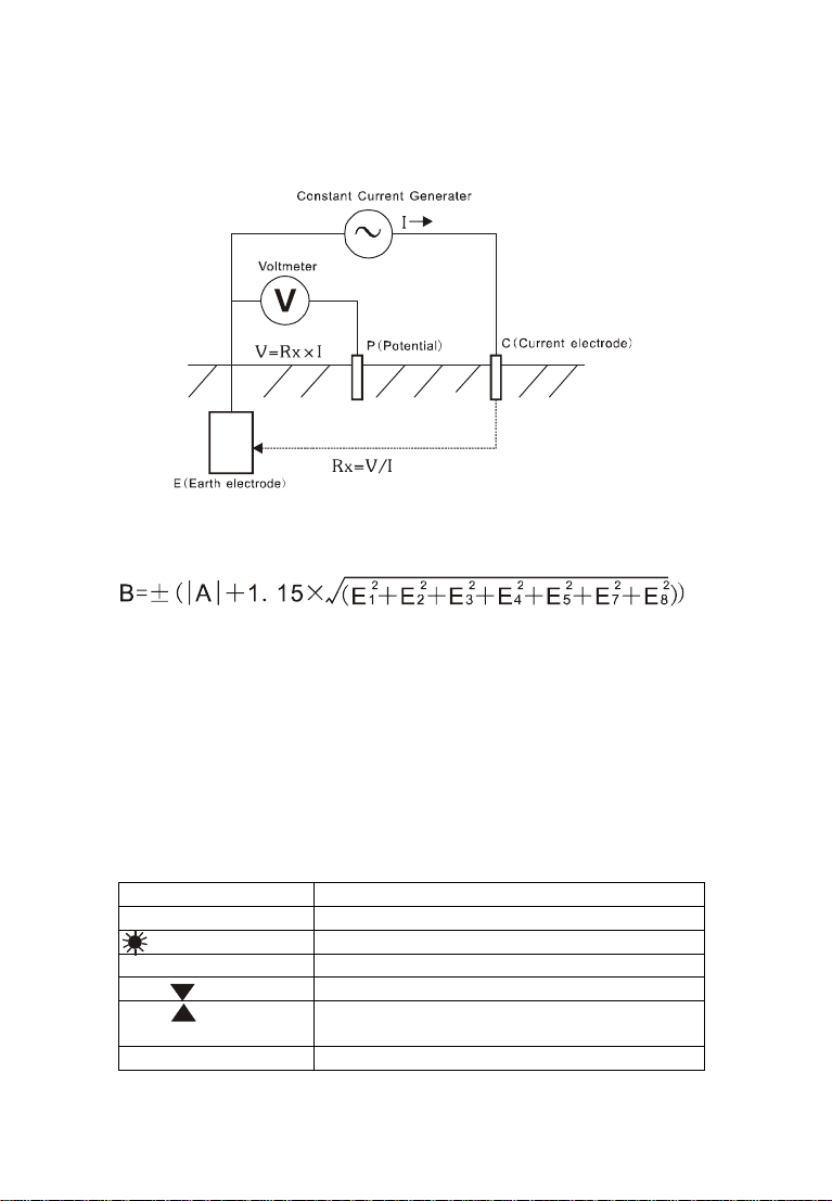
VI.Measuring Principle
1. Voltagetogroundmeasurementadoptsaveragevaluerectificationmethod.
2.The groundingresistancevalue ismeasured using the ratedcurrentchange
method,thatis,therated currentI(30mAMax,128Hz)flowing between the
8
measuring objectE(ground electrode)and H(currentelectrode); seeking
potentialdifferenceVofEandS(voltage electrode),then todeterminethe
groundresistanceRx
Rx=V/I
3Itsoperatingerror(B) isan errorobtained within therated operating
conditions,andcalculated withthe intrinsic error(A) and theerror(E) due to
variations.
A:Intrinsicerror
E1:Variation due toposition change
E2:Variation due topower supplyvoltage
E3:Variation due to temperaturechange
E4:Variation due tointerferencevoltagechange
E5:Variation due tocontact electrode resistance
E7:Variation due tosystemfrequencychange
E8:Variation due tosystemvoltagechange
VII. Function QuickCheck
POWER SwitchOn/Off
MEM Databrowsing/valuesetting
Backlight Button
Backlight control
TFRTButton Start measuring
Button Deletedata measurementselection
Button Wireresistancecheck/deletedata
measurementselection
Set Button Set alarmvalue/deletedata

9
MEMButton DataLock/Store/View
Button Alarmfunction start/alarmthreshold
setting
R and U Measuregearselection
VIII. Operation Methods
1.SwitchOn/Off
Turnthe function keytothecorrespondingtestposition and turniton.
Turnthe function keytotheOFF position toturnofftheinstrument, themeter
will be automaticallyturned off, and afterturning off, itwill be turnedtothe
OFF positionandrestart..
2.BatteryVoltageCheck
Afterswitchon,ifLCD displays lowbatteryvoltage icon““,which
indicatesthat batteryvoltage islow, andpleasereplacethebatteryintime.
3.Ground voltagemeasurement
Pleasemakesuretestingwire plug hasbeentotallyinserted intotesters
correspondinginterfaceanditmaycausemeasurementvalueerrorfor
incompleteinsert orpoorcontact.
The testercannotbeusedfor commercialpower supplyvoltage
measurement.Forspecial situationthatneedstomeasure,itcan only
useV,Einterfacetoconnectformeasurement.Itisnotallowed to
measure commercialpower voltagein thecaseofshortcircuitofH,S
interface.Otherwise,measuringvoltage in theearthing circuitofcutout
switchmaycausecutoutswitchstart.
Onmeasuringearthingvoltage,pleasedonotimpose
over600V
voltage
on measurementconnectors.
Whenmeasuringgroundvoltage,donottouchexposedconductorsto
avoidelectric shock.
Aftertheauxiliarygrounding rod andtestline areconnected,switchthe
functionbuttonUtothevoltagelevel,the LCD displaysthe voltagetoground,
and themeasuredvoltagetoground cannotexceed 600V.
Ingeneral,formeasuring earthingvoltage,itisonlytoconnectthe
testing wires corresponding to V, E interface.Asshown:

10
4.WireResistance Verification
Inordertoimproveprecisionand stabilityoffield measurementofearth
ground resistance,avoid errordue towireresistancechange due toprolonged
usageoftestingwires;avoiderrordue totesting wirethatisfailedtobefully
inserted intotesterinterfaceorbypoorcontact; avoid errordue tousers
replacingorlengthening testingwiresand etc.,wireresistanceverification is
speciallydesigned,whichismoreaccurateon lowvalue resistance
measurement.
Asshowninthefigurebelow,pressthe functionbuttonRbutton toswitch
tothecorrespondinggroundresistancemeasurementposition,press
button tostart verification.During verification,During the calibration,the
LED indicatorflashes.TheLCD countsdown.Afterthe calibrationis
completed,theLCD displaysthe lineresistanceandstoresthevalue.The
checkedlineresistancevalueisautomaticallydeducted fromthisstart-up
groundresistancemeasurement.
Shutdowndoesnotsavethecalibrationline resistance.The nexttimeyou
turnonthepower, you need to verifyagain..
5.Grounding Resistance Precision Measurement
Pleasemakesuretestingwire plug hasbeentotallyinserted intotesters
correspondinginterfaceanditmaycausemeasurementvalueerrorfor
incompleteinsert orpoorcontact.
Astolowvalueearthgroundresistancemeasurement,itwill be more
accurateafter wire resistanceverification.
On measuringearthingvoltage,between Eand Cinterface,itwill occur
the maximumvoltage about50V!Pleasedonotimposevoltageon
measurementinterface.Pleasepayattentiontoavoidingelectricshock
accident.
Onmeasuringearthgroundresistance,testingwirescannotbemixed
Note
Beforemeasuringearthground resistance,firstlyplease
confirmvoltagetogroundmustbe lowerthan10V.
Otherwise,themeasurementvalue maycauseexcessive
error.Atthattime,firstlycutoffpoweron measuredearthing
equipmentand makeresistancemeasurementafterthe
earthing voltage is reduced.
11
around,whichshallbemeasuredseparately.
Trytochoosethespotwithmore watertodeeplyburyauxiliaryearthing
rodsHandS,inorder toreduceauxiliaryearthgroundresistanceand
thusreduceindicationerror.
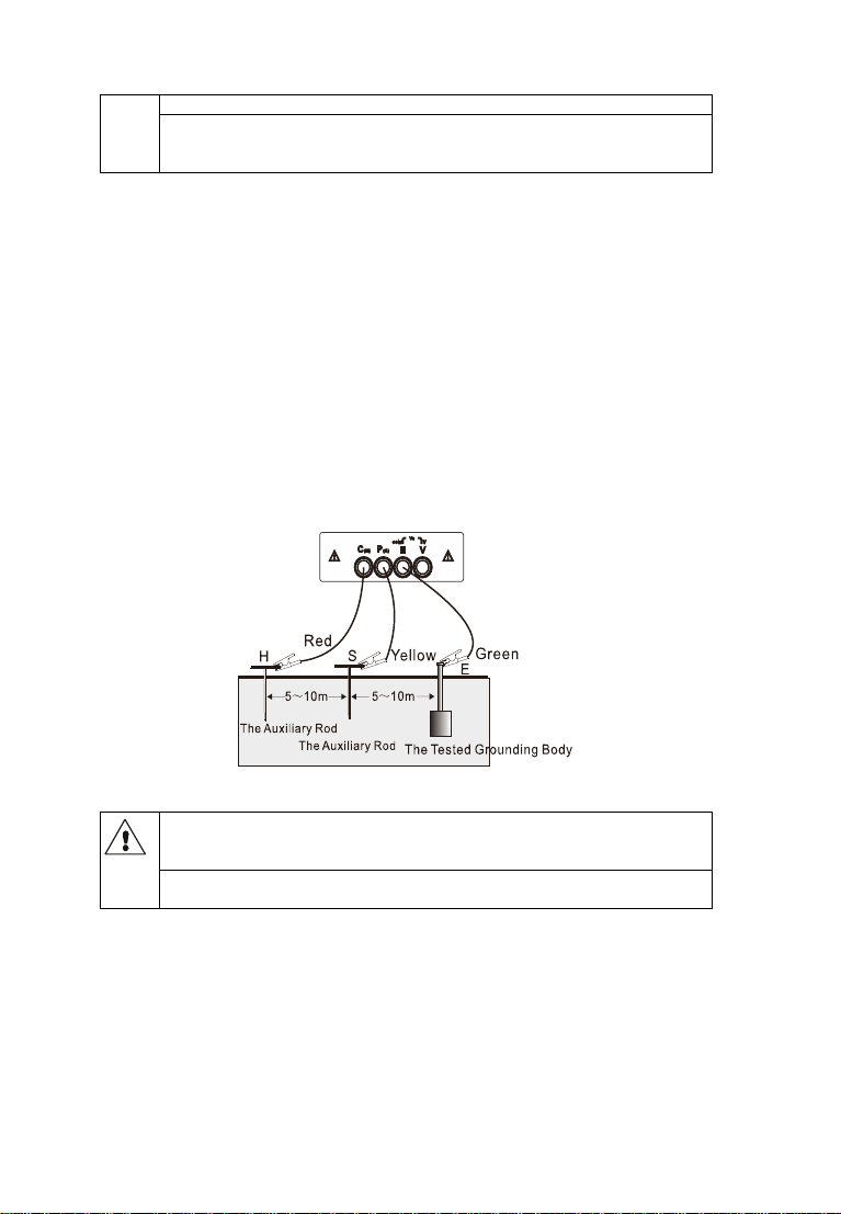
Precisionmeasurementgrounding resistanceadoptsthree-wireconnection,
auxiliarygrounding rodandtestlineareallconnected,switchfunctionto
measureresistanceRmode,presskeytopress “TFRT”keytostart
measurement,LED indicatorflashesduring measurement,LCD countdown
display,aftermeasurementis completedThe indicatorisoffandtheLCD
showsthemeasuredvalue.Startingfromthe measured object,insertthe
auxiliarygroundingrod intothe earthevery5to10 meters,connectthe
groundingtestlines(red,yellow,and green)fromthe H,S, and Eportsofthe
metertothe auxiliarycurrentelectrodeH, auxiliaryvoltageelectrodeS, and
groundelectrode E under test.Asshown:
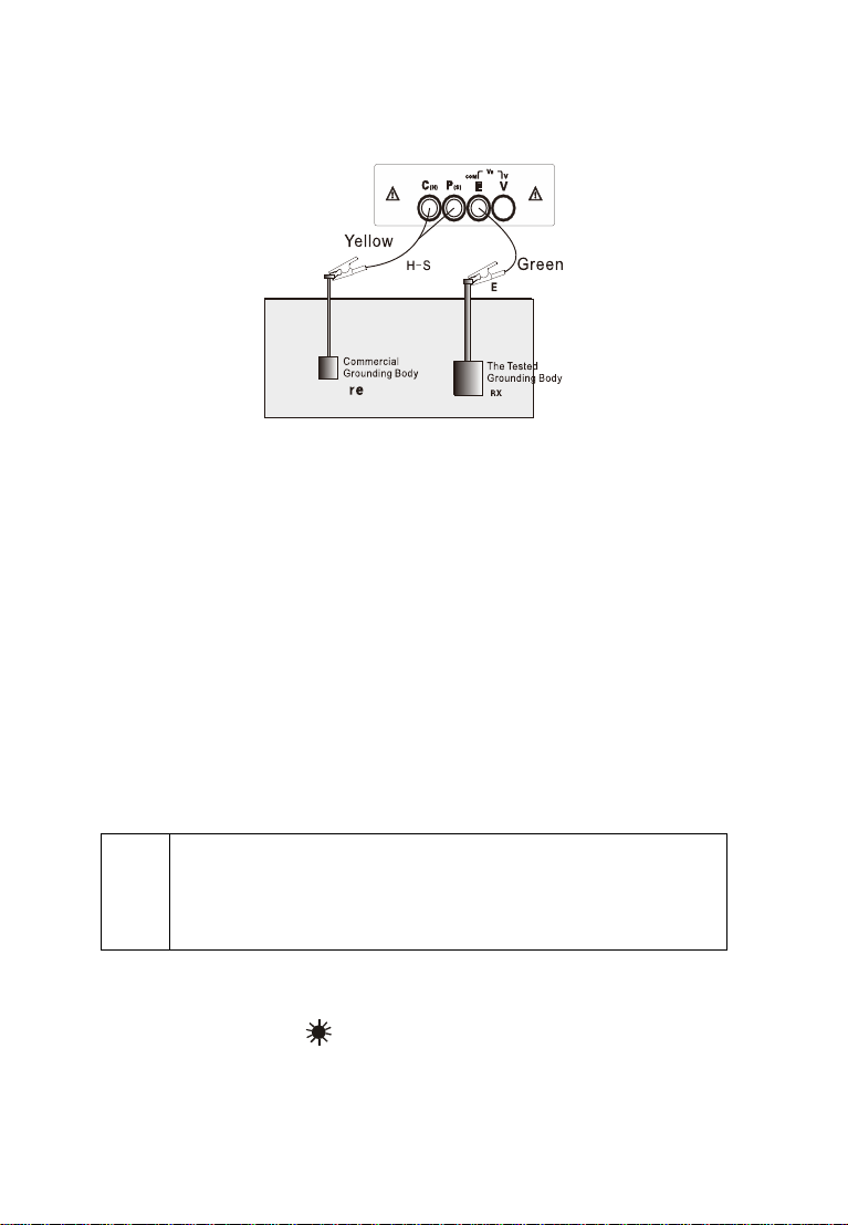
6.SimpleMethod forMeasuring Ground Resistance
Whenselectcommercialusepowersupplysystemearthasauxiliary
earthelectrode, itmustusedetectortoconfirm thatitisthe earthground
electrodeforcommercial usepower supply system.
Itis forbiddentousethisTestertoconfirmearthelectrode ofcommercial
usepower supply system
Thismethodisasimplemethod formeasurementthatdoesnotuse
auxiliaryearthing rod,takingthe earthelectrode withtheminimalexisting
earthgroundresistancevalueasauxiliaryearthelectrode,and connecting by
twosimpletesting wires(inwhichH,Sinterfacesareinshort circuit).Itcan
makeuseofmetalpipes,firehydrantsandothermetalburied objects,
common earthing ofcommercial electric powersystemorlightningprotection
earthgroundelectrodeandotherstoreplaceauxiliaryearthing rodsH, S,and
payattention toremoveoxide layeron theconnection pointoftheselected
12
metalauxiliaryearthing objectwhen making measurement.
Earthgroundresistancesimple testingwireconnectionisasfollowing
figure, andrefertoprecision measurement for other operations.
Simplemethodformeasurementofearthgroundresistance,itsreading
on Testeristhetotalvalueofearthgroundresistancevalue ofmeasured
earthing object and that of commercialearthing object, namely:
RE=RX re
Inwhich: RE isthe Tester reading value;
RX is the earthground resistancevalue of measured earthing
object;
re istheearthground resistancevalue ofcommon earthing
object likecommercial usepower system.
Then,the earthgroundresistancevalueofmeasured earthing objectis:
RX=RE-re
Adopting simplemethodformeasurementofearthgroundresistance
shalltrytoselectthe earthing objectwithlowvalue asthe auxiliaryearth
groundelectrode,thenthetester readingvaluecanbemoreapproaching
totruevalue.Pleasetakeprecedenceinselectingmetalwaterpipes,fire
hydrantsasauxiliaryearthelectrodewhen measuring.
Note
Simplemethod for measurementofearthgroundresistancealsoneeds
toconfirmthatvoltagevaluetoground mustbelower than10V.If the
voltagevalueisover10V,themeasurementvalueofearthground
resistancemaycauseerrorandatthattime,itshallfirstlycutoff power
on measured earthingequipmentand makeresistancemeasurement
after theearthingvoltageisdecreased.
7.BacklightControl
Afterstartup,press ““buttontoturnon oroffbacklight. The backlight
functionissuitable todarkspot. Itwill defaultbacklightturn-offforeach
startup.
13
8.Alarm Settings
Afterpoweron,short press “”toturnonandoffthe alarmfunction.
Short press "SET"keytosetthe resistancealarmvalue,press ""keyto
movethe cursor,press ""or""keytochange thecurrentsize,andthen
press"SET"keytosaveandexit. When the measuredvalueisgreaterthan
the alarmcriticalsetting value and thealarmfunctionisturned on,the meter
displaysthe “”symbolandissuesa “beep-beep-beep--”alarmsound.
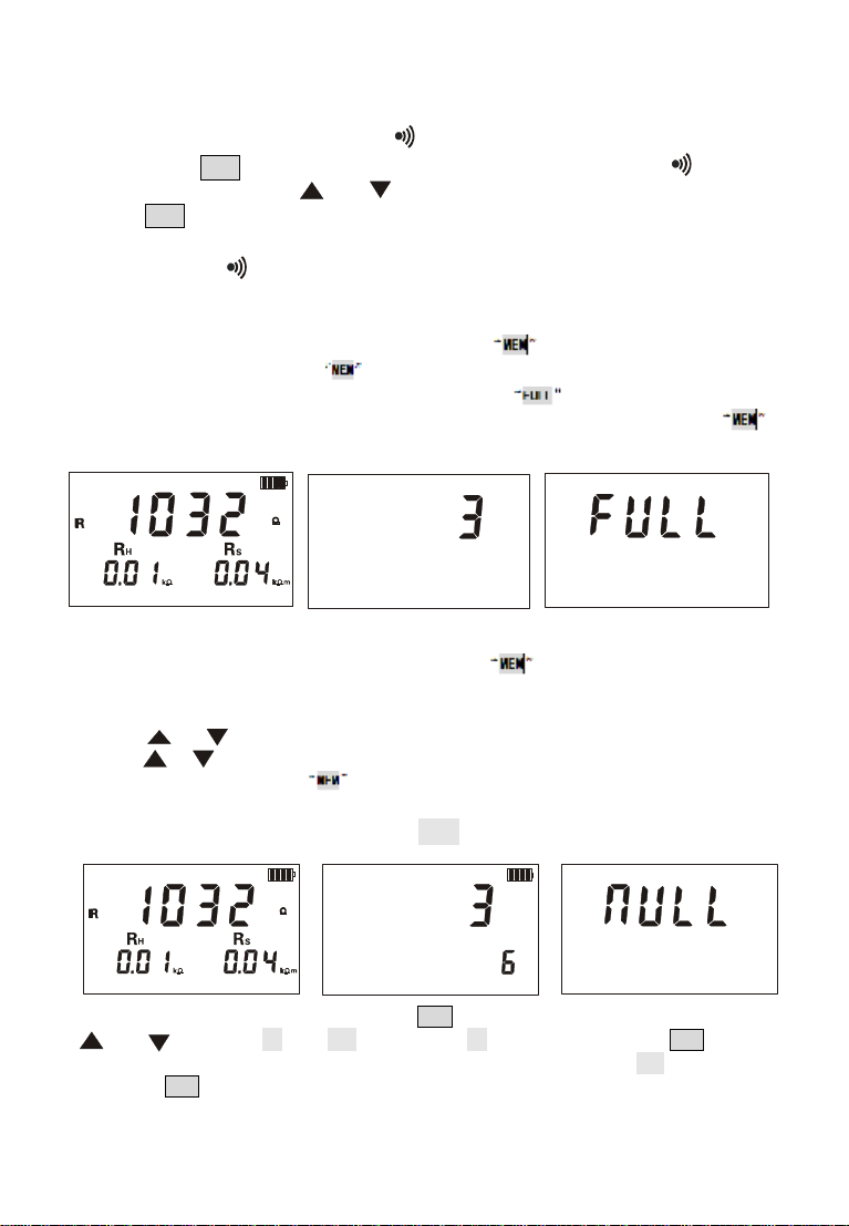
9.DataLock/Storage
Startup oraftermeasurement, press buttontolock current
displayed data,showing icon andautomaticallystorewithserial
numbers.If storageisfull,the Testerwill display icon.toremovelock.
Asshownin figurebelow:the lock measurementdatais1032Ω,press
buttonsaveasthe 3thgroup of data .
10.DataReview/Deletion
Startup oraftermeasurement, press buttonforalongertime
(over3seconds)toenterdatareading,the interfacecorresponding tothe
storeddatainterfaceand thestoreddatagroupnumberflashalternately.
Pressorbutton toselectreading data group numberbystepvalue1,
pressorbutton constantlytoselectreadingdatagroupnumberbystep
value 5,and thenpressbutton toexit fromreading.
Inthe figurebelow,the number3is the currentgroupnumber,and 6is the
total groupnumber, LCD will display“NULL”,see the abovefigure.
Under datareading status, press SET buttontoenter datadeletion, press
ortoselect “no”or “YES”,selecting “no”and thenpressing SET button
fornotdeleting and returndatareading status,selecting “YES”and then
pressing SET button fordeleting stored dataanditwill showasaboveright

14
figureafter deletion.
IX.BatteryReplacement
The instrumentispoweredbysix1.5VLR14 batteries.Whenthe
batterypowerisreduced, thepowerindicatorbarisreduced. Whenthe
voltage dropsto 5V, the batterysymbol “”isdisplayed.
X.Accessories
Tester 1PC
Tester Bag 1PC
AuxiliaryEarthingRod 2PCS
TestingWire 3PCS
Simpletesting wire 2PCS
1.5V battery 6PCS
Manual , QualificationCertificate 1 SET

Table of contents
Other Electronic Technologies Test Equipment manuals


