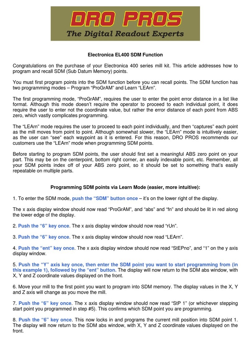
electronica EMS-i EL 400 Series User manual

Using Segmented Linear Error Compensation (SLEC)
to calibrate magnetic scales with an EL400 display:
Congratulations on the purchase of your Electronica 400 series kit. This article addresses how to calibrate
magnetic scales using Segmented Linear Error Compensation (SLEC). Note: SLEC is a much more
advanced form of correcting for error compensation. Most calibration issues (if any) can be corrected
using Linear Error Compensation (LEC), not SLEC. DRO PROS does not recommend utilizing SLEC
unless you’re already familiar with advanced error compensation procedures.
SLEC works by applying a graphed correction factor to your scale from a chosen reference point (referred
to as the Master Reference Point). In order for SLEC to work properly, it must always know where the
master reference point is. As such, every time the display is powered up, the master reference point must
be ‘recalled’. While performing SLEC can make every measurement along the scale “perfect”, for most
users, having to recall your master reference point every point you power up the display is going to be
more inconvenient than it is beneficial.
The following procedure assumes that your kit has been properly installed and the readhead / scale gap
has been properly set with the included shim. While the “best” calibration results are obtained with a
laser, it is possible to achieve satisfactory results with a high grade gauge block combined with a high
quality plunge type dial indicator. Best results are usually obtained by the simplest, most robust setup. Be
sure to also check / adjust your machines jib play before attempting to calibrate scales.
SLEC consists of three separate steps. First, you must discover and designate a “master” reference point
for applying SLEC. Second, the SLEC correction factors must be entered. Third, the master reference
point must be referenced before each operating session (or each time the display is powered up if the
display has been turned off).
Step 1 - Find and designate a Master Reference Point.
Magnetic scales have factory embedded, permanent reference marks located along the length of the
scale, approximately every two inches. Our first step is to find, and then designate, which mark is the
“best” to use as the Master Reference Point. Typically, it would be the reference mark closest to the
negative end of our scale. As these reference marks are not visibly marked on the scale, we must first
discover where they are, and then choose which mark is the closest to the end of the scale while still
allowing the readhead to ‘sense’ it.
Move your readhead to the far end of the scale. Be careful to not run the readhead into the endcap.
Press the “homing” function button.
You should see “hoME” on the X axis display window.
Push the “ent” button once. You should see “SELECt” on the X axis display window.
Push the “X” button once. The X axis display window should now be flashing "0".
Move the X axis of the mill until the X axis display starts counting normally. As soon as the X axis begins
counting, reverse the travel, and go back so that the X axis window displays “0.0000”. This indicates the
exact position of a reference mark. With a scribe/pen, mark the location relative to the readhead, so that
you know specifically where the reference point is located.

Repeat this process several times until you’re certain you’ve found the reference mark nearest the end of
your scale, that the readhead is able to ‘sense’. We’ll refer to this as our Master Reference Point. Mark it
conspicuously as you will need to reference this point again.
Step 2 - Enter the SLEC correction factors.
Move your machine to the very end of the scale so that you’re positioned before (to the negative side of)
your Master Reference Point.
Push the “wrench” button once – it’s on the lower left of the display.
The top axis display window should now read “SELECt”.
Push the “X” button once. The x axis display window should now read “LinEAr”.
Push the “2” (down arrow key) five times. The x axis display window should now read “CALib”.
Push the “ent” button once. The x axis display window should now read “LEC”.
Push the “6” key once. The x axis display window should now read “SLEC”.
Push the “ent” button once. The x axis display window should now read “AUto”.
Push the “ent” button once. The x axis display window should now read a blinking “0”, and the y axis
display should read “hoMinG”.
Move your machine to cross your Master Reference Point. As it does, the x axis display will begin
counting normally. Position the machine where you want to begin SLEC. This is the start point of your first
SLEC “segment”. Note: The Master Reference Point and the starting point of your first SLEC segment
may or may not be co-located.
Push the “ent” button once. The x axis display window should now read “0.0000”, and the y axis
display should read “S no 01”. This represents the beginning, or zero point, of all your subsequent
segment corrections. We’ll refer to this point as our Zero Point.
Move your machine to the end point of your first segment. Ignore the numerical value displayed on the x
axis.
Push the “6” key once. The x axis should read “0”.
On the numerical keypad, input the distance from the master zero point as measured by your standard,
followed by pushing the “ent” button once. The x axis display window should now read a numerical
value (ignore this), and the y axis display should now read “S no 02”.
Move your machine to the end point of your next segment. Keep in mind that each segment need
not be the same length as the others. The only thing to remember is that you must continually be
moving in a positive direction, away from the Zero Point.
Push the “6” key once. On the numerical keypad, input the distance from the Zero Point as
measured by your standard, followed by pushing the “ent” button once. The x axis display
window should now read a numerical value and the y axis display should read “S no XX”, where
“XX” represents the segment number.
Repeat the previous two indented steps for all your remaining segments.
When finished inputting your segment correction factors, Push the “2” (down arrow key) key until the x
axis display window reads “SAv ChG”.
Push the “ent” button once. The x axis display window should now read “rSt oEm”.

Push the “2” (down arrow key) twice. The x axis display window should now read “End”.
Push the “ent” button once. The display will now read “MC rEF”. This indicates the display needs you
to ‘find’ the Master Reference Point in order to properly apply the SLEC (continue to Step 3).
Step 3 - Find the Master Reference Point.
Remember, the Master Reference Point must be “found” each time the display is powered up (indicated
by an axis reading “MC rEF”).
Move your machine so that the readhead is close (~ ½” or so) to the Master Reference Point you marked
in Step 1 before pressing the “homing” function button.
Press the “homing” function button.
You should see “homE” on the X axis display window.
Push the “6” key once. The x axis display window should now read “MC rEF”.
Push the “ent” button once. You should see “SELECt” on the X axis display window.
Push the “X” button once. The X axis display window should now be flashing "0".
Move the X axis of the mill past the Master Reference Point until the X axis display begins counting
normally. It may be necessary to move the table back and forth past the reference mark a few times
before the readhead "senses" it. While you're doing this, stay close to the Master Reference Point, and
do not move the table further than necessary. As soon as the readhead captures the Master
Reference Point, the X axis display will suddenly begin counting ‘normally’.
If you inadvertently capture a reference point other than your Master Reference Point, the display will
apply your SLEC correction factors incorrectly. If this happens, simply repeat the above steps until you
capture the master reference point.
Other manuals for EMS-i EL 400 Series
2
Table of contents
Other electronica Power Tools manuals
