Electronics Line iconnect User manual


ii
iConnectControlSystemUserManual
CatalogNumber:ZI0548F(06/10)
Alldataissubjecttochangewithoutpriornotice.
Hereby,ElectronicsLine3000Ltd.declaresthatthisControlSystemisincompliancewith
theessentialrequirementsandotherrelevantprovisionsofDirective1999/5/EC.
Copyright©2010ElectronicsLine3000Ltd.Allrightsreserved.

iii
Quick Reference Guide
Function Press… Additional Information
ARM
FULL PART PERIMETER
If One-Key Arming is disabled on the
Control System, enter your user code when
arming.
The default master code is 1234.
INSTANT ARM
Hold down this key
until “Instant Arming
OK?” is displayed.
Then Press .
Instant arming cancels the entry delay
after Part or Perimeter arming. This feature
can be enabled by your installer.
DISARM [USER CODE] Entering your user code also silences the
siren in the event of an alarm.
PANIC
ALARM +
FIRE
ALARM +
MEDICAL
ALARM +
Press these buttons together and hold
them down to generate an alarm.
MENU MODE then [USER CODE]
Use the menu navigation buttons (/)
until the required menu item is displayed
then press . Alternatively, enter the
shortcut (e.g. 21 for Bypass Zones).
CHECK TROUBLE
CONDITIONS
Use this key scroll
the system trouble
list.
Pressing also silences any trouble tones
that may be sounded by the system.
SWITCH HA/PGM
UNIT ON then [HA UNIT #]
SWITCH HA/PGM
UNIT OFF then [HA UNIT #]
Enter the HA module number in two digits
(e.g. 03, or 30 for PGM).
SERVICE CALL
then
press
and hold “Service Call Dialing” is displayed. The
number dialed for the service call is
programmed by your installer.
FIVE SPEED
DIAL NUMBERS
Press this key, then
press and hold the
speed dial number
button.
Numbers 1 to 5 can be programmed by
master access in the menu telephone #
[5.2-5.6].
GLOBAL
CHIME then Use the menu navigation buttons (/) to
choose enable or disable, then press .
RECORD
MESSAGE then
PLAY
MESSAGE then
After recording a message, “Message
Waiting” is displayed until the message is
played back.
The Message Center is an optional feature
that is included with certain versions of
iConnect Control System.
OR OR

iv
Telecontrol Commands
Function Press… Function Press…
2-WAY AUDIO DISARM
FULL ARM SIREN CANCEL
HA UNIT XX ON*then EXTEND CALL
HA UNIT XX OFF then DISCONNECT then
For Partitioned Systems
Function Press… Function Press…
FULL ARM then SYSTEM DISARM then
PARTITION 1 ARM then PARTITION 1 DISARM then
PARTITION 2 ARM then PARTITION 2 DISARM then
*forPGMXX=30

v
Table of Contents
Quick Reference Guide ................................................................................... iii
1. Introduction and Overview ...................................................................... 1
1.1. Documentation Conventions...................................................................... 1
1.2. Security System Components .................................................................... 2
1.3. System Monitoring ................................................................................... 2
1.4. Home Automation .................................................................................... 3
1.5. Self-Monitoring........................................................................................ 3
1.6. Telephone Control.................................................................................... 3
1.7. Vocal Message Annunciation...................................................................... 4
1.8. Web Access............................................................................................. 4
2. The User Interface................................................................................... 5
2.1. Front Panel (LCD Configuration)................................................................. 5
2.2. Front Panel (LED Configuration)................................................................. 7
2.3. Alarm Sounding Patterns........................................................................... 9
2.4. LCD Keypad ...........................................................................................10
2.5. Keyfobs .................................................................................................10
2.6. Wireless Terminal....................................................................................11
3. Arming and Disarming ........................................................................... 15
3.1. System Type - Partitioned /Unpartitioned...................................................15
3.2. Arming Modes: Unpartitioned Systems.......................................................15
3.3. Arming Modes: Partitioned systems...........................................................15
3.4. Arming the System .................................................................................16
3.5. Disarming the System .............................................................................19
3.6. Arm Status and Other System Status Indication..........................................20
3.7. Arming Tones.........................................................................................21
3.8. Remote Arming/Disarming .......................................................................21
4. Panic Alarms.......................................................................................... 23
4.1. Keypad Alarms .......................................................................................23
4.2. Keyfob Panic Alarm .................................................................................23
4.3. Medical Emergency .................................................................................23
5. Home Automation and PGM.................................................................... 24
5.1. Keypad Control.......................................................................................24
5.2. Keyfob Control........................................................................................24
5.3. Telephone Control...................................................................................25
5.4. SMS Control...........................................................................................25
5.5. Scheduling (not relevant to PGM)..............................................................25
6. Telecontrol............................................................................................. 27
6.1. Calling your Home...................................................................................27
6.2. Service Call............................................................................................29
6.3. Two-Way Audio after an Alarm .................................................................29
6.4. Two-Way Audio Follow-Me........................................................................29
6.5. Simplex Mode.........................................................................................29
7. Advanced System Operation .................................................................. 30
7.1. Cancel Report.........................................................................................30

vi
7.2. Zone Bypassing/Unbypassing ...................................................................30
7.3. User Codes.............................................................................................31
7.4. Follow-Me ..............................................................................................33
7.5. Speed Dial Numbers................................................................................34
7.6. Event Log ..............................................................................................34
7.7. Service Menu..........................................................................................35
Appendix A: Menu Structure.......................................................................... 40
Appendix B: Web User Application................................................................. 41
Log In Page ......................................................................................................41
The Main Page ..................................................................................................42
Options Available from Main Page........................................................................43
Video...............................................................................................................48
Appendix C: Glossary..................................................................................... 49

1. Introduction and Overview
iConnect User Manual 1
1. Introduction and Overview
ThisusermanualexplainsallyouneedtoknowaboutyouriConnectsecuritysystem
andprovidesstep‐by‐stepinstructionsforallthesystem’suserfunctions.Inadditionto
theexplanationyouwillreceivefromyourinstaller,weurgeyoutoreadthismanualso
thatyoucantakefulladvantageofyoursystem’sfeatures.Keepthismanualinan
accessiblelocationforfuturereference.
TheiConnectsystemhasmanyfeaturesinordertosuitawiderangeofapplications.
Thismanualoutlinesallofthesefeaturesbutitislikelythatthereareoptionsthatare
notrelevanttoyoursystem.Ifyouhaveanyquestionsregardingtheavailabilityofthe
featuresdescribedinthemanual,pleaseaskyourinstaller.
1.1. Documentation Conventions
Inordertosimplifytheproceduresthatappearintherestofthismanual,thefollowing
conventionsareused:
Item… Description…
Select… Use the arrow buttons to scroll through the options and press .
From the Event
Log Menu, select
Clear Log.
Enter the main menu by pressing and entering your user
code. Using the arrow buttons, navigate until you reach
Event Log and press . Using the arrow buttons, navigate
until you reach Clear Log and press .
From the Service
menu, select
Time/Date, Set
Date.
The same as above only this time you are navigating
through three menu levels.
[7012] The shortcut to a specific menu item from the main menu. In
this case, this is the shortcut for Set Date. These appear in
the procedures as an additional aid to menu navigation.
[#3] A shortcut to a specific item in a sub-menu. For example,
[#3] is the shortcut to HA Schedule in the sub-menu that is
opened once you have selected the Home Automation unit
you want to program.
, buttons buttons that appear on the keypad ( , )
5.InterfaceTest The text that actually appears on the LCD display (italics).
Note
Important caution, please pay attention.

1. Introduction and Overview
2iConnect User Manual
1.2. Security System Components
YoursecuritysystemismadeupofaControlSystem,varioussensorsandanumberof
optionalperipheraldevices.Thissectionexplainstheroleofeachcomponentinyour
system.
Control System
The Control System is the brain of the system. It
communicates with all the devices connected to the
system. For example, in the event of a burglary, a sensor
sends a signal to the Control System indicating that it has
sensed motion on the premises. On receiving this signal,
the Control System makes the decision to report the alarm
to your monitoring service and activate the siren.
Sensors
Sensors are the devices that protect your home, alerting the Control
System when there is a breach in security. Magnetic contacts protect
your doors and windows while motion sensors are able to detect an
intruder moving across its field of view. Additionally, smoke sensors can
be installed to provide an early warning in the event of a fire.
Keyfobs
Keyfobs are hand-held transmitters that are used to operate the
system. Various keyfobs are available providing a number of functions.
For example, arming/disarming the system, sending panic alarms and
various home automation functions.
Keypads
The keypads enable you to communicate with the Control System in
order to perform a number of different functions. The main function you
can perform using a keypad is to arm the system when leaving your
home and to disarm on your return.
Sirens
While the Control System includes a built-in internal siren, it is possible
that you also have an external siren installed. The sirens are sounded
during certain alarm conditions serving to warn you and ward off
intruders.
1.3. System Monitoring
Whenaneventoccurswithinthesystem,theControlSystemsendsamessagetoyour
monitoringservicedescribingtheexactnatureoftheevent.Thisenablesthemonitoring
servicetotaketherequiredaction.Systemmonitoringcanimplementeitherregular
telephoneorcellularcommunication.

1. Introduction and Overview
iConnect User Manual 3
IMPORTANT:Thereisacommunicationdelayof30secondsinthisControl
Systemfornon‐firealarms.Thisdelaycanbereducedto15secondsoritcanbe
increasedto45secondsattheoptionoftheenduserinconsultationwiththe
installer.Firealarmsarecommunicatedimmediately.
1.4. Home Automation
Anoptionalexpansionmodulecanprovideyouwiththeabilitytocontrolupto16
individualelectricalappliancesorlightsusingthefrontpanelkeypad,wireless
keypads,telecontrol,SMS,orkeyfobs.Additionally,eachappliancecanbe
programmedtobeturnedonandoffautomaticallyaccordingtovariousschedules
andsystemstatusconditions.
1.5. Self-Monitoring
Inadditiontotheabilitytoreporttoamonitoringservice,thesystemcanalsosendyou
andotherusersnotificationwhenaneventoccurs.Thismaybeintheformofvocal
messagesplayedoverthetelephoneor,ifyoursystemsupportscellularcommunication,
youcanreceiveinformationonsystemstatusviaSMS.Ifanalarmoccursonthe
premises,youareinformednomatterwhereyouareintheworld.
1.6. Telephone Control
DTMF Telecontrol
TheiConnectoffersarangeof“Telecontrol”featuresthatprovideremoteaccessvia
thetelephone(PSTNorCellular).Thesefeaturesincluderemotearming/disarming,
controloverHomeAutomationunits,PGMoutputactivation/deactivation,siren
cancelandTwo‐WayaudioviatheControlSystem’sbuilt‐inmicrophoneandspeaker
–seep.27,
6Telecontrol.
TheTwo‐WayAudiofeaturesallowyoutocontactyourhomedirectlyintheeventofan
alarmorsimplytocheckyourhomewhileyouareaway.
A sensor detects. The Control S
y
stem is alerted. An alarm is generated and the
monitoring service is notified.

1. Introduction and Overview
4iConnect User Manual
SMS Control
Usingyourcellularphone,youcanalsosendSMScommandstoarm/disarmthesystem,
commandstotheappliancescontrolledbytheHomeAutomationfeatureandtoPGM
output,andgetconfirmationwhenthecommandisreceived–seep.21,Remote
Arming/DisarmingviaSMS,andp.25,
5.4SMSControl.
1.7. Vocal Message Annunciation
Vocalmessageannunciationisanoptionalfeaturethat,ifenabledinprogramming,
causesthesystemtoplayshortmessagesthatindicatesystemstatus.
1.8. Web Access
TheWebApplicationprovidesaninterfacetoyoursecuritysystemfromyourInternet
browser.ViatheWebyoucanperformawiderangeoftaskssuchasarm/disarm,
zonebypass,usercodemanagementandhomeautomationcontrol.Additionally,you
cansetupthecontactswhomyouwishtobealerted(byemailortextmessage)when
selectedeventsoccur.
Theapplicationalsoallowsyoutocheckyourhomeatanytimeeitherbyviewinga
historyofrecenteventsthathaveoccurredorbyviewingstreamingvideofrom
camerasinstalledonthepremises.Forfurtherinformation,seep.41,AppendixB:Web
UserApplication.

2. The User Interface
iConnect User Manual 5
2. The User Interface
Thereareseveralmethodsyoucanusetooperatethesystem.Apartfromthekeypadon
thefrontpanel,yoursystemmayincludeanumberofperipheraldevices,suchas
keypadsandkeyfobs.
Thischapterprovidesabriefintroductiontoeachofthedevicesyoucanusetooperate
thesystem.Itisimportantthatyoufamiliarizeyourselfwiththesedevicesbefore
readingthefollowingchaptersthatshalldescribesystemoperationinfurtherdetail.
Thefrontpanelisthemainuserinterfacethatprovidesyouwithallthefunctionsyou
needtocontrolyoursecuritysystem.iConnectGPRSControlSystemisavailableintwo
frontpanelconfigurations:LCDandLED.
2.1. Front Panel (LCD Configuration)
LCDFrontPaneldisplayandLEDsinformyouofsystemarmingstatus,powerfailures,
andsystemtroubleconditions.Itsalphanumerickeypadenablesyoutoenteryouruser
codewhenarminganddisarming,andtosilencethesirenintheeventofanalarm.
Arming Keys
Threearmingkeysareavailable:Full,Part,andPerimeter.Thesebuttonsarmthesystem
usingoneofthethreearmingmethods.One‐keyArmingisanoptionthatis
programmedbyyourinstaller.
System
Status
indicators
LCD
Display
Arming Keys
Alpha-
numeric
Keypad
Menu
Navigation
Keys
Home
Automation
Keys

2. The User Interface
6iConnect User Manual
Service Call Button
TheServiceCallbuttonenablesyoutocontactthemonitoringserviceandtalk
toanoperator.
Toinitiateaservicecall,presstheuparrowbutton,thenpressandholddownthe
ServiceCallbutton.
Speed Dial
TheSpeedDialfeatureenablesyoutocallfromthecontrolsystemuptofivedifferent
telephonenumbersprogrammedinthesystem–seep.34,
7.5SpeedDialNumbers.
TodialoneoftheprogrammedSpeedDialnumbers,presstheuparrowbutton,
thenpressandholddownthenumberbutton1to5untilʺCallSpd#Dialingʺ is
displayed.Whenfinishedspeaking,pressthebuttontodisconnect.
Vocal Message Recording and Playback
LCDfrontpanelallowsyoutorecordashortmessagethatmaybeplayedbacklaterby
anotheruser–seep.35,
7.7.ServiceMenu,MessageCenter.
Home Automation and PGM On/Off Buttons
On
PressingoneoftheHomeAutomationbuttonsfollowedbythe
unitnumber(01‐16,or30forPGM)enablesyoutocontrol
lightsandappliancesinyourhome,activateanddeactivate
PGMoutput.
PressingbothHomeAutomationbuttonssimultaneously
generatesanSOSpanicalarm.
Off
System Status LEDs
TheSystemStatusindicatorsprovideessentialinformationonthestatusofthesystem
suchasarm,disarm,alarmandpowerfailureconditions.
OK LED Status Meaning
Off Both AC and Battery power are disconnected.
On Green System Power status is OK and there is no System Trouble.
Flashing Green Open Zone. Check that the windows and doors are closed
and no movement is detected by the sensors within the
protected area.
On Yellow System Trouble.
Flashing Yellow (slow) Battery low from the Control System or transmitters.
Flashing Yellow (fast) AC loss.
Flashing Yellow
(intermittent) System Trouble in addition to AC loss/Low Battery.

2. The User Interface
iConnect User Manual 7
LED Status Meaning
Off The system is disarmed.
On Green The system is armed.
Flashing Red An alarm has occurred. Alarm indication is cleared the next
time you arm the system or view the relevant event in the
event log.
Alarmindicationisnotdisplayedafterasilentpanicalarm.
System Trouble Indication
Intheeventthatthesystemdetectsatroublecondition,“SystemTrouble”appearson
thedisplay.Toidentifytheproblem,scrollthroughthetroublelistbypressing.
Scrollingthetroublelistalsosilencessystemtroubletonesthatmaybesoundedif
enabledinprogramming.Whenthetroubleconditionisrestored,itisremovedfromthe
systemtroublelist.
2.2. Front Panel (LED Configuration)
Asthenamesuggests,theLEDFrontPanelusesonlyLEDstoinformyouoftheControl
Systemstatus.InadditiontoSystemStatusLEDs(OKandʺ!ʺ),therearethreeArming
StatusLEDs:full,part,andperimeter.Thethree‐buttonkeypadallowsyoutomake
servicecall,recordandplayaudiomessage,andtoactivateSOSpanicalarm.
System
Status
LEDs
Arming
Status
LEDs
Service
Call
Button
Message
Play
Button
Message
Record
Button

2. The User Interface
8iConnect User Manual
Service Call Button
TheServiceCallbuttonenablesyoutocontactthemonitoring
serviceandtalktoanoperator.
Toinitiateaservicecall,pressandholddowntheServiceCall
buttonforafewseconds.
Service Call
Vocal Message Recording and Playback
Message Play
UsingMessagePlayandMessageRecordbuttonsontheLED
TopCoveryoucanrecordashortmessagethatmaybeplayed
backlaterbyanotheruser.Whenthereisanewmessage
waiting,theMessagePlaybuttonisflashingfast.
Toplaybackarecordedmessage,presstheMessage
Playbutton.
Message
Record
Torecordamessage,presstheMessageRecordButton,recordyourmessage,thenpress
theMessageRecordbuttonagaintostoprecording.Themessageisthenplayedback
andsaved.
Duringrecording,theMessageRecordbuttonislit.Whenyouhave5seconds
leftoutofthe20secondstimeout,theMessageRecordandtheServiceCall
buttonsbacklightsflash.
SOS Panic Alarm Activation
UsingtheLEDTopCover,youcanactivateanSOSPanicalarmbypressingtheService
CallandMessagePlaybuttonssimultaneously.
System and Arming Status LEDs
TheSystemStatusindicatorsprovideessentialinformationonthestatusofthesystem
suchasarm,disarm,alarmandpowerfailureconditions.
OK LED Status
(Green) Meaning
Off System cannot be armed
On The system is ready for arming.
Flashing Open Zone. Check that the relevant entrances are secured (i.
e. windows and doors are closed and no movement is detected
by the sensors within the protected area).

2. The User Interface
iConnect User Manual 9
!LED Status
(Yellow) Meaning
Off No trouble condition in the system.
On System Trouble.
Flashing
(slow) Backup battery low or low battery from transmitters.
Flashing (fast) AC loss.
Flashing
(intermittent) System Trouble in addition to AC loss/Low Battery.
, & LEDs Meaning
Off The corresponding arming method is not active.
In partitioned systems, the corresponding
partition is disarmed. If all the three LEDs are
off, the system is disarmed.
Flashing Red The exit or entry delay for this arming mode is
counting down.
On Green The System is armed using the arming method
shown by this LED. In partitioned systems, the
corresponding partition/whole system is armed.
All the three Arm Status
LEDs flash Red An alarm has occurred. Alarm indication is
cleared the next time you arm the system or
view the relevant event in the event log.
2.3. Alarm Sounding Patterns
Thefollowingtablesummarizesvariousalarmssoundedbythecontrolsystem.
Alarm Alarm Sounding Pattern Description
Burglary ON (continuously)
Fire ON - ON - ON, 1.5-second pause, ON - ON – ON......
Gas ON - ON - ON - ON (short bursts), 5 second pause, ON - ON -
ON - ON......
Medical ON (continuously) – only applicable for Medical alarm from zone
Flood 4 rapid tones sounded once per minute (same as Trouble tones)
Environmental 4 rapid tones sounded once per minute (same as Trouble tones)

2. The User Interface
10 iConnect User Manual
2.4. LCD Keypad
Inadditiontothefrontpanelkeypad,yoursystemmayincludeoneormoreLCD
keypads.ThelayoutoftheLCDkeypadissimilartothefrontpanelkeypadandmostof
thefunctionalityisidentical.
2.5. Keyfobs
TheiConnectsupportstwotypesofkeyfobtransmitter.TheEL‐2714includestwo
buttons(B1andB2)thatyoucanprogramindividually.ThedefaultfunctionsforB1and
B2buttonsarearmingfunctions.Armingfunctionsofthekeyfobforpartitionedand
unpartitionedsystemsaredescribedinp.17,ArmingwiththeKeyfob.Alternatively,
yourinstallercanprogramthesebuttonstocontrolaspecificHAunitorPGMoutput.
TheEL‐2611hasonebuttonusedforMedicalAlarm.
Thefunctionsofthebuttonsoneachkeyfobareshownbelow:
EL-2714 EL-2611
Medical
B2: Perimeter Arm,
HA/PGM, Arm/Disarm
Partition 2
B1: Part Arm, HA/PGM,
Arm/Disarm Partition 1
Full Arm Disarm
LCD
Display
Menu
Navigation
Keys
Menu
Navigation
Keys
System
Status
LEDs
Arming
Keys
Alphanumeric
Keypad

2. The User Interface
iConnect User Manual 11
2.6. Wireless Terminal
TheEL‐2724WirelessTerminalisanintelligenttwo‐waywirelesskeypadwithalarge
display.Apartfromservingasanadditionalarmingstation,theEL‐2724providesmemo
recordingoptions,controloverupto16homeautomationdevices,andpanicalarm
function.YoucanarmanddisarmthesystemwiththeWirelessTerminalusingthe
smartkey(ifsupported).TheEL‐2724ʹsdisplayshowsarmingstatus,powerstatus,
alarms,andtime.ThesystemsupportsuptofourWirelessTerminals.
WirelessTerminalEL‐2724doesnotsupportpartitioning.
Keypad
TheWirelessTerminalkeypadistheuserinterfacethatprovidesyouwiththefunctions
youneedtocontrolyoursecuritysystem.Threearmingkeys(Full,Part,andPerimeter)
allowyoutoarmthesystemusingoneofthethreearmingmethods–seep.15,
3.Arming
andDisarming.One‐keyArmingisanoptionthatisprogrammedbyyourinstaller.Ifthis
optionisdisabled,youmustalsoenterausercodewhenarming.
Function Press… Additional Information
ARM
FULL PART PERIMETER
If One-key Arming is disabled, enter your
user code or place a registered smartkey (if
supported) against the center of the
smartkey reader.
DISARM [USER CODE or SMARTKEY] Entering your user code also silences the
siren in the event of an alarm.
OR OR

2. The User Interface
12 iConnect User Manual
PANIC/SOS
ALARM
Press these two buttons together and hold
them down to generate an alarm.
SWITCH HA
UNIT ON then [HA UNIT #]
SWITCH HA
UNIT OFF then [HA UNIT #]
Enter the HA module number in two digits
using number buttons (e.g. 03) or 30 for
PGM.
RECORD
MESSAGE then During recording the both LEDs flash in
tandem. Press to stop recording; the
message is automatically played back.
PLAY
MESSAGE then To abort message play press while
message is playing.
SET TIME
Press and hold down .
When the numbers start
blinking, adjust the time by
pressing .
Press once to switch between hours
and minutes. Press to exit and save
changes.
TheCancelbutton clearsthekeypadintheeventthatyoupressedabutton
bymistake.Thesystemwaitsforyoutoenterallfourdigitsbeforeitdecidesthat
thecodeisincorrect.PressingtheCancelbuttoncausesthekeypadtodisregard
whatwaspreviouslyenteredenablingyoutostartagain.
System Status LEDs
TwoSystemStatusLEDsindicatearmingandpowerstatusoftheWirelessTerminal:
OK LED Status LED Status Meaning
Off The Wireless Terminal is disconnected
from all power sources.
On Green The keypad is powered by AC and the
battery is not low.
Flashing Yellow
(slow) Local backup battery low.
Flashing Yellow
(fast) Wireless Terminal AC loss.
Off The system is disarmed.
On - Green The system is armed.

2. The User Interface
iConnect User Manual 13
Flashing Red An alarm has occurred. This alarm
indication is reset when the system is
armed using any of the three arming
methods.
Alarm indication is not displayed after a silent
panic alarm.
Flashing Green Flashing Red You are recording a message.
Display
ThefollowingtabledescribestheWirelessTerminaldisplayinterface.
Icon Symbol Description
Full Arm
The system has been armed in Full arm mode.
Full arming is designed for situations where the
house is empty and the entire system is armed1.
Part Arm
The system has been armed in Part arm mode.
Part arming is designed for situations where a
specific part of the house is armed and a
separate part of the house is still occupied.
Perimeter
Arm
The system has been armed in Perimeter arm
mode. Perimeter arming is designed for
situations where the occupants are at home and
the perimeter (e.g. doors, windows) is
protected.
Disarm
No arming modes are currently activated. The
icon changes when the Control System has been
armed again.
Alarm
The Alarm icon flashes from the moment an
alarm occurs until the next time the system is
armed.
SOS Panic
Alarm
Indicates that an SOS Panic alarm has been
activated from a Panic zone (typically a Panic
button), a keypad or a keyfob.
Battery
Status The battery status of the Wireless Terminal.
AC Status
The AC power status of the Wireless Terminal. If
the icon is crossed-out, it means AC power loss
(i.e. the Wireless Terminal is disconnected).
Clock A four-digit clock display.
1TheiconshowsallthethreearmingmodesonlywhenarmedfromtheTerminalitself.Ifarmed
fromtheControlSystem,theiconalwaysshowsfullarming.

2. The User Interface
14 iConnect User Manual
Smartkey (Model Dependant)
TodisarmtheSystemusingsmartkey:
Placearegisteredsmartkeyagainstthecenterofthesmartkeyreader.
Whenthesmartkeyisread,thekeypadwillsoundabeep–thesystem
isdisarmed.
ArmingtheSystemusingSmartkeyispossiblewhenOne‐KeyArmingis
disabled.
ToarmtheSystemusingsmartkey:
PressoneoftheArmingKeys,thenplacearegisteredsmartkey
againstthecenterofthesmartkeyreader.Whenthesmartkeyisread,
thekeypadwillsoundabeep–thesystemisarmed.
Other manuals for iconnect
6
Table of contents
Other Electronics Line Security System manuals
Electronics Line
Electronics Line iconnect User manual

Electronics Line
Electronics Line EL-2626AC User manual

Electronics Line
Electronics Line Summit 3208GLD User manual
Electronics Line
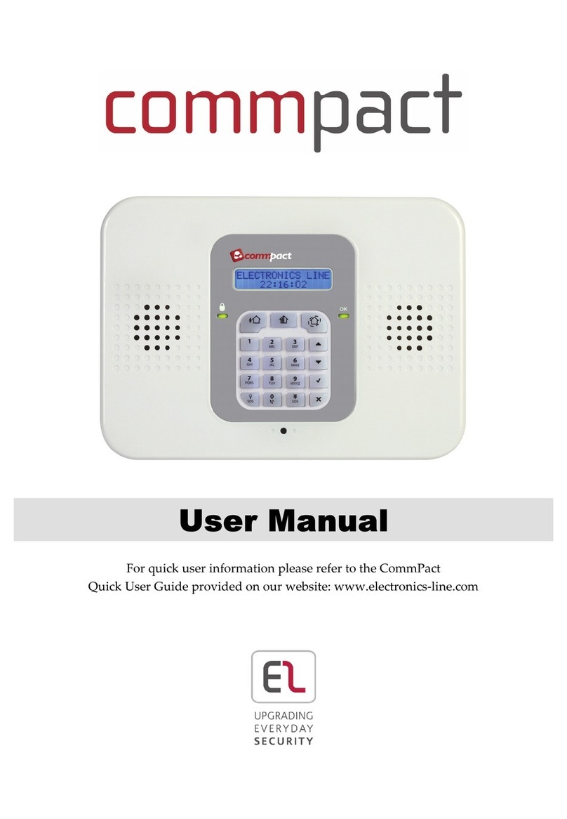
Electronics Line Commpact User manual
Electronics Line
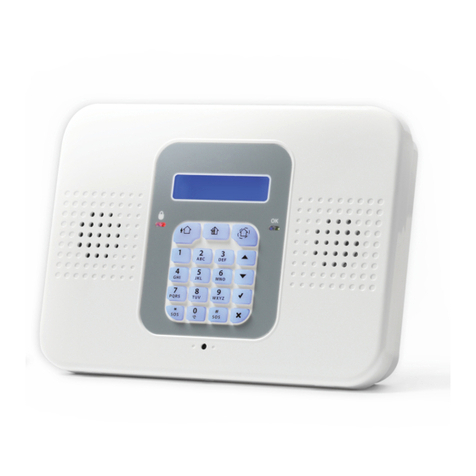
Electronics Line SecuPlace Instruction manual
Electronics Line
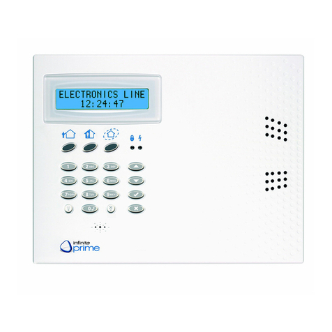
Electronics Line infinite prime User manual

Electronics Line
Electronics Line infinite prime Operating instructions

Electronics Line
Electronics Line Penta XL series User manual
Electronics Line
Electronics Line iconnect User manual
Electronics Line
Electronics Line iConnect EL-4723 User manual
