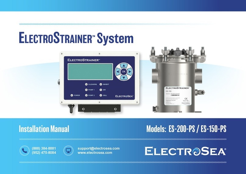
ELECTROSEA ElectroStrainer ES-200 User manual

Installation Manual Models: ES-200 / ES-150
ElectroStrainer™System
(888) 384-8881
(952) 475-8084
www.electrosea.com

1
U.S. Patent No. 11,027,991 and other U.S. and Foreign Patents Pending
COPYRIGHT © 2022
No part of this publication may be reproduced, translated, stored in a retrieval system, or transmitted in any form or by any means electronic, mechanical, photocopying, recording or otherwise
without prior written consent by ElectroSea, LLC. Every precaution has been taken in the preparation of this manual to ensure its accuracy. ElectroSea assumes no responsibility for errors and
omission. Neither is any liability assumed for damages resulting from the use of this product and information contained herein.
1Table of Contents
Introduction
Table of Contents 1
ElectroSea and ElectroStrainer System 2
Components 3
Safety and Pre-Installation Descaling 4
Optimal Performance & Maintenance
Optimal Performance and Strainer Flow Alert 5
Cell Indicator 6
Installation Overview
Electrical Connection Overview 7
Seawater Connection Overview 8
Canister Assembly
Canister Preparation 9
Mounting Options 10
ClearVis™Flow Sensor 11-12
Chlorinated Return Line 13
Reassembly 14
Control Unit
Mounting and Wiring 15
Specifications
Specifications 16
Warranty
Warranty Terms and Conditions 17-18

2
U.S. Patent No. 11,027,991 and other U.S. and Foreign Patents Pending
Introduction 2
ElectroSea®
ElectroSea was created when owners of a sportfishing vessel identified a better way to prevent biofouling in their seawater cooling system. Solving complex technical
problems is their expertise. With more than 100 issued U.S. patents and 350+ foreign patents in advanced technologies, our Executive Management Team has been developing
innovative solutions for more than 50 years. With an experienced team of ‘old salts’ who eat, sleep, and breathe boating, ElectroSea will improve your time on the water.
ElectroStrainer™System
ElectroStrainer is a revolutionary seawater biofouling prevention device, a sea strainer, and a smart seawater flow monitoring unit all combined into a single system.
ElectroStrainer provides an entirely new way for boaters to prevent biofouling, barnacles and bioslimes from clogging your sea strainers and seawater pipes for air
conditioners, chillers and refrigerators. ElectroStrainer provides ease of use never seen before in a sea strainer and completely redefines seawater system maintenance.
• ElectroStrainer is a Biofouling Prevention Device
ElectroStrainer continuously creates a safe and effective level of chlorine to protect your entire seawater system. ElectroStrainer contains a Cell with a proprietary
mixed-metal oxide coating; when electrified it acts as a catalyst to generate chlorine naturally from the seawater passing through it. No chemical additives are required.
• ElectroStrainer is a Sea Strainer
Typical sea strainers become clogged as bioslime, algae, and barnacles build-up over time in the strainer pores. ElectroStrainer solves this problem by preventing unwanted
marine growth using electrochlorination generated directly in its sea strainer. Strainer pores remain open, free and clear so protected seawater can pass downstream to
cooling equipment and decreases the frequency of strainer cleaning.
• ElectroStrainer is a Smart Seawater Flow Monitoring System
ElectroStrainer provides real-time monitoring with Smart Strainer Alert technology and automatically notifies you to check the strainer if it requires attention.
ElectroStrainer monitors your vessel’s seawater flow 24/7/365 days a year and displays the real-time seawater flow rate.

3
U.S. Patent No. 11,027,991 and other U.S. and Foreign Patents Pending
ElectroStrainer System
Canister Assembly
The ElectroStrainer System includes the Control Unit, Canister Assembly and all components listed below:
Control Unit
• (1) Canister, Strainer Basket, and Cell
• (1) ClearVis Flow Sensor
• (4) Hose Connectors
• (1) Top Side Mounting Bracket
• (1) Bottom Side Mounting Bracket
• (2) Machine Screws M5 Round Head
• (3) Machine Screws M6 Round Head
• (1) Lock Nut M6
• (1) Machine Screws M8 Round Head
• (8) Mounting Screws #12 x 1.25”
(3.2cm) Flat Head
• (1) Chlorinated Return Line Tubing
• (1) Return Line Tee-Fitting
• (1) Return Line Valve
• (4) Return Line Hose Clamps
• (1) Strain Relief Clamp for Return Line Tubing
• (1) Optional Return Line Canister Cap
Components
3
Major components shown above
• (1) Control Unit
• (3) Cables
— (1) Power: 20’ (6.1m)
— (1) Cell: ES-200: 20’ (6.1m), ES-150: 12’ (3.7m)
— (1) Flow Sensor: ES-200: 20’ (6.1m), ES-150: 12’ (3.7m)
• (4) Mounting Screws #10 x 1” (2.54cm)

4
DO NOT perform acid descaling after the ElectroStrainer System has been installed. Descaling acids will damage the
ElectroStrainer and void the Warranty.
U.S. Patent No. 11,027,991 and other U.S. and Foreign Patents Pending
Safety Considerations
Improper installation can result in unsatisfactory performance, premature failure, damage to systems in the seawater circuit and/or to the vessel.
WARNING Indicates a hazardous situation which, if not avoided, could result in death or serious injury.
CAUTION Indicates a hazardous situation which, if not avoided, could result in minor or moderate injury.
NOTICE Indicates a hazardous situation which can cause damage to personal property, environment, or equipment.
Pre-installation Descaling of Seawater Conduits
Pre-installation descaling ensures any existing biofouling that has accumulated on the interior seawater lines are removed. If seawater lines are impacted with
barnacles and marine growth, then ElectroSea recommends professional descaling prior to installing the ElectroStrainer System. By starting with descaled and
clean seawater lines, you will realize the full benefit of the ElectroStrainer System. For new vessels, descaling is not necessary.
Safety and Pre-Installation 4
NOTICE
Low seawater flow may damage cooling system and other components that depend on this water for proper operation.
It is the owner’s responsibility to monitor the vessel’s seawater flow rate and perform any necessary maintenance.
NOTICE
ElectroStrainer is an all-in-one sea strainer and electrochlorination System. ElectroStrainer replaces existing sea
strainers. If there is an existing sea strainer in the vessel, then remove it and install the ElectroStrainer Canister in the same location.
NOTICE

5
U.S. Patent No. 11,027,991 and other U.S. and Foreign Patents Pending
Optimal Performance and Strainer Flow Alert
5
Strainer Flow Alert: The Strainer Flow Alert feature monitors seawater flow through ElectroStrainer. This smart strainer system notifies the user that the
ElectroStrainer basket contains debris such as seaweed or mud; or part of the seawater circuit such as the intake screen or thru-hull fitting is partially blocked; or
the seawater pump is producing low flow and requires maintenance. The Strainer Flow Alert feature allows the user to set a minimum seawater flow rate threshold
value and time duration. If the seawater flow rate drops below a minimum value for a period of time, then “Check Strainer / Flow Alert” will flash on the display (no
audible alert). Flow rate can be set in GPM or LPM, and time duration in minutes. To set the Strainer Flow Alert value, go to MENU, Flow Alert, and enter the desired
threshold flow rate and time duration for notification.
Flow Alert feature is default OFF from ElectroSea and must be set by the installer or end user.
ElectroStrainer will continue generating chlorine even after a Strainer Flow Alert occurs.
If a Strainer Flow Alert occurs:
1. Check vessel intake screens for blockage or debris,
2. Check seawater pump output, impeller or other causes of low flow,
3. Check ElectroStrainer basket for debris, seaweed or mud.
Optimal Performance
Constant Chlorinated Seawater Flow: The ElectroStrainer System should be powered ON and have seawater flowing through it whenever possible.
This provides the vessel’s seawater circuit with constant chlorinated seawater to prevent unwanted marine growth. Intermittent or stagnant seawater
that is not continuously electrochemically treated allows growth of marine microorganisms. Barnacles have the innate ability to close themselves off and survive
intermittent exposure to biocidal agents.
• DO NOT turn off seawater pumps, air conditioners, or chillers for an extended period of time.
Inspect the vessel for problem areas:
• Pre-existing biofouling in seawater lines prior to ElectroStrainer installation.
• Clogged seawater intakes.
• Impacted, blocked or occluded lines from debris lodged in plumbing.
• Sporadic demand valve areas; depending on the system, valves that turn on and off can foster unwanted marine growth.
Strainer Flow Alert
>-Flow Alert -Update
-Display
-Cell
-Default -Exit
NOTICE
NOTICE

6
CELL Indicator: The Control Unit will display “SALINITY/CELL”, “% OUTPUT” and illuminate the red CELL LED in various conditions. This is not an immediate cause for concern
and may be temporary depending on seawater salinity level. ElectroStrainer will continuously attempt to generate chlorine and automatically resume standard operation
when conditions are resolved. The CELL indicator will be illuminated if any of the following conditions occur for multiple consecutive days:
• Water salinity is below 20 parts per thousand (most common cause of CELL indicator notice).
• ElectroStrainer Cell cable or its connectors have been compromised.
• ElectroStrainer Cell has excessive mud or other debris.
• ElectroStrainer Cell is at the end of its useful life.
Water Salinity
• Vessels often encounter brackish or freshwater when cruising inland, and from extended storms and freshwater run-off.
• Low salinity is the most frequent cause of the CELL Indicator.
• ElectroStrainer will not display “CLEANING” or generate chlorine while vessel is operating in freshwater.
RESOLUTION: Vessel returns to seawater with adequate salinity.
ElectroStrainer Cell Cable
• The ElectroStrainer Cell cable and connections must not be spliced, cut, compromised, or damaged.
• Inspect the Control Unit to Cell cable carefully. Look for any corrosion at the connectors.
RESOLUTION: Replace the ElectroStrainer Cell cable if it is compromised.
Excessive Mud or Other Debris
• If there is excessive mud or other debris, then the ElectroStrainer Cell may require a brief rinse with freshwater.
ElectroStrainer Cell at End of Life
• When the ElectroStrainer Cell has reached the end of its useful life it can no longer generate chlorine. The Cell life is dependent on flow rate, hours of use, seawater
quality and other factors.
RESOLUTION: Contact your ElectroSea dealer.
U.S. Patent No. 11,027,991 and other U.S. and Foreign Patents Pending
6
Cell Indicator
Cell Indicator
ESTUARY
OCEAN

7
U.S. Patent No. 11,027,991 and other U.S. and Foreign Patents Pending
Installation Overview
7
ELECTROSTRAINER CONTROL UNIT MUST BE LOCATED WITHIN:
ES-150 ES-200
Canister Assembly 12 ft. (3.7m) 20 ft. (6.1m)
Flow Sensor 12 ft. (3.7m) 20 ft. (6.1m)
Power Source 20 ft. (6.1m) 20 ft. (6.1m)
1.
Electrical Connection Overview
PART NUMBER DESCRIPTION
CBL01-CC-EXT-15FT 15’ (4.6m) Cell Extended Cable
CBL01-CC-EXT-20FT 20’ (6.1m) Cell Extended Cable
DO NOT cut, extend, or splice the Cell cable.
Longer Cell cables are available from ElectroSea.
DO NOT connect multiple Cell cables together.
The Cell Extended Cables in the table below show the total cable length
from the Control Unit to the Cell.
Modification of ElectroStrainer Cell cable will impair operation.
OPTIONAL CABLE ACCESSORIES:
NOTICE
NOTICE
Bonding wire to
vessel ground
ES-150: 12’ (3.7m)
ES-200: 20’ (6.1m)
2. Canister Assembly must be connected to vessel’s bonding circuit.
24VDC
ES-150: 20’ (6.1m)
ES-200: 20’ (6.1m)

Before beginning ElectroStrainer System installation
turn OFF all seacock valves in the seawater circuit.
Use marine grade hose and double clamp with two
stainless steel clamps, reversing the clamps. Failure to properly secure
seawater connections could result in sinking the vessel.
DO NOT exceed ElectroStrainer pressure specifications.
All seawater plumbing connections must be performed by
a qualified marine installation professional.
PTFE should not be used on plastic connections. Avoid over
tightening plastic parts they may crack and result in sinking the vessel.
DO NOT decrease seawater flow below manufacturer’s
specifications for downstream cooling equipment.
Limit the use of 90° elbows as they restrict flow and
cause pressure drop.
ElectroStrainer is made of 2205 Duplex Stainless Steel for
corrosion resistance. Do not connect dissimilar metals to it if possible.
Use only original parts supplied by ElectroSea. They are
made of special titanium, stainless and other high quality materials. Use of
non-factory or substitute parts will void the Warranty.
8
U.S. Patent No. 11,027,991 and other U.S. and Foreign Patents Pending
Installation Overview 8
Seawater Connection Overview
1. Locate the vessel’s seawater intake pump, strainer (if existing), and seacock
shut-off valve. Turn OFF ALL seacock shut-off valves in the seawater circuit at
or below the water line. This includes any output seacocks to prevent back
siphoning.
2. The Canister Assembly should be installed before the pump, and before
any seawater cooled equipment such as air conditioners, chillers, etc.
If there is an existing sea strainer, then remove it and install
ElectroStrainer Canister in the same location. Canister Assembly should be
installed at or below the water line, and as close to the thru hull as possible.
3. A chlorinated return line may be connected after the flow sensor and
seawater pump to return chlorinated seawater directly to the ElectroStrainer
Canister Assembly. This will help to prevent growth at the inlet of the strainer
basket. See page 13 for details.
NOTICE
WARNING
NOTICE
WARNING
WARNING
NOTICE
NOTICE
DO NOT USE DESCALING SOLUTIONS, ACIDS OR CLEANING
CHEMICALS AFTER ELECTROSTRAINER HAS BEEN INSTALLED. THIS WILL DAMAGE
THE ELECTROSTRAINER CANISTER ASSEMBLY AND VOID THE WARRANTY.
WARNING
WARNING
WARNING

9
U.S. Patent No. 11,027,991 and other U.S. and Foreign Patents Pending
ElectroStrainer Canister Installation
9
Canister Preparation
1. Unsecure the pressure ring by turning the wing
nuts counterclockwise.
3. Remove the Cell Assembly. Lift straight up by
the black plastic cover. Do not lift or pull on
the cable. Set the Cell Assembly aside in a safe
location. Remove the strainer basket. Now you
can work just with the Canister for mounting.
1 2
2. Remove the pressure ring.
3

10
1. The Canister Assembly must be installed so it is level and at or below the waterline.
2. The Canister Assembly can be mounted using several different options as shown below:
U.S. Patent No. 11,027,991 and other U.S. and Foreign Patents Pending
ElectroStrainer Canister Installation 10
Mounting Options
OPTION A
Base Tab Mounting
WARNING
OPTION B
Side Mounting
1
Mount
Level
1. Mount Canister to flat interior engine room surface.
2. Insert (3) #12 mounting screws into base tab
to secure the Canister.
3. Do not screwthrough hull of boat.
WARNING
1. Attach Top mount brackets with (2) M5 screws.
2. Attach Bottom bracket with (2) M6 screws (front side)
or (1) M8 screw (back side).
3. Secure to stringer or other appropriate load supporting
vertical surface with (8) #12 mounting screws.
Top
Bracket
Bottom
Bracket
Mount the Canister Assembly level to prevent accumulation of excess air/gas.

11
1. The Canister Assembly has directional IN and OUT labels. Seawater MUST enter at the IN port
and flow through and exit at the OUT port.
Failure to route seawater in the direction of the IN and OUT labels
will result in improper operation of the ElectroStrainer System.
2. The ClearVis Flow Sensor has a flow direction arrow and seawater must enter and exit
according to the marked arrow. ClearVis Flow Sensor MUST BE installed on the same
seawater line/pipe as the ElectroStrainer Canister. The Flow Sensor tells ElectroStrainer
how much chlorine to generate. DO NOT install the Flow Sensor on a separate or ancillary
seawater line/pipe from ElectroStrainer.
The Flow Sensor is made of glass filled nylon for superior strength.
However, this makes the threads less malleable and rougher than other plastics. When
sealing to the Flow Sensor, it is recommended that thread sealant, without PTFE, is used.
The ClearVis Flow Sensor measures the velocity of seawater using
speed of sound technology. It is preferable to have 12” (30.5cm) of straight hose before and
after the ClearVis Flow Sensor. This decreases seawater turbulence and improves the speed,
accuracy and precision of the ClearVis Flow Sensor measurement.
DO NOT place a 90° elbow or other flow restrict plumbing fittings
immediately after the ClearVis Flow Sensor output. The Flow Sensor will
be unable to obtain a consistent reading and Control Unit may be unable to enter the
CLEANING mode. The flow sensor can be placed either upstream (suction side) or
downstream (pressure side) of the seawater pump that ElectroStrainer resides on.
U.S. Patent No. 11,027,991 and other U.S. and Foreign Patents Pending
ElectroStrainer Canister Installation
11
Canister and Flow Sensor
NOTICE
Flow Sensor
must be oriented
so seawater
follows direction
of flow arrow
NOTICE
NOTICE
DO NOT INSTALL A 90°°
ELBOW ON THE OUTPUT
OF THE FLOW SENSOR
3
OUT
1
IN
2
NOTICE

12
There are two options for the location of the ClearVis Flow Sensor:
4. The “BEST” location for the ClearVis Flow Sensor is after the Canister output
with at least 12” of straight hose before and after the Flow Sensor.
The ClearVis Flow Sensor can also be installed on the pressure side
of the pump.
5. An “ACCEPTABLE” location for the ClearVis Flow Sensor is on the output of
the ElectroStrainer Canister with at least 12” of straight hose after
the Flow Sensor.
All seawater flowing through the ElectroStrainer
Canister Assembly must flow through the Flow Sensor. DO NOT split
or divert seawater before the ClearVis Flow Sensor as this will tell the
Control Unit to generate an incorrect amount of chlorine.
6. Connect threaded male or female PVC hose connectors to ElectroStrainer
Canister, and/or flow sensor as shown in picture 4 or 5.
7. Use thread sealant without PTFE on all connections.
PTFE should not be used on plastic parts. Avoid over
tightening plastic parts they may crack and result in sinking the vessel.
8. Use two hose clamps, reversing the clamps, over flexible hose connections.
9. Add flexible hose hanger, hose strap or hose support bracket within 12” of
ClearVis Flow Sensor. Make sure the ClearVis Flow Sensor is supported.
U.S. Patent No. 11,027,991 and other U.S. and Foreign Patents Pending
ElectroStrainer Canister Installation 12
Canister and Flow Sensor
WARNING
BEST: 12” of straight hose before and after Flow Sensor
ACCEPTABLE: Flow Sensor at ElectroStrainer output with 12”
of straight hose after Flow Sensor
10
Flow
Sensor
Support
weight of hose
4
9
10
Support
weight of hose
Flow
Sensor
5
9
WARNING

13
ElectroStrainer can be installed without a
chlorinated return line. The chlorinated return line provides
the greatest protection from biofouling in the strainer basket.
IF THE CHLORINATED RETURN LINE WILL NOT BE USED, THEN USE
ONLY THE SPECIAL 2205 ALLOY PLUG PROVIDED. DO NOT USE
ANOTHER TYPE OF METAL PLUG. This will void the Warranty.
Note: there may be a small amount of biogrowth in the strainer
basket if the chlorinated return line is not used.
The chlorinated return line decreases the
overall flow rate to downstream equipment. Check downstream
equipment flow requirements and DO NOT add a chlorinated
return line if this will result in low flow to cooling equipment.
1. To prevent growth at the inlet of the ElectroStrainer basket, a chlorinated return line should be
connected from the pressure side of the pump to the Canister Assembly’s 90-degree fitting
located under the inlet port.
2. Connect this chlorinated return line with a tee-fitting and ball valve to the pressure side of the
pump. Note: The source for the chlorinated return line must be after the seawater pump
(on the pressure side) and after the ClearVis Flow Sensor.
3. Connect the chlorinated return line tubing suppled with the Canister Assembly to the 90-degree
hose barb fitting directly under the inlet port. Secure the tubing with two hose clamps, reversing
directions, and clamp securely.
4. Secure the chlorinated return line tubing with Strain Relief Clamp. The Strain Relief Clamp can be
connected to the feet or wall bracket. Use included mounting screw or nut and bolt.
U.S. Patent No. 11,027,991 and other U.S. and Foreign Patents Pending
ElectroStrainer Canister Installation
13
NOTICE
Chlorinated Return Line to Canister
4
NOTICE
1
3
2

14
14
U.S. Patent No. 11,027,991 and other U.S. and Foreign Patents Pending
ElectroStrainer Canister Installation
Canister Reassembly
Gasket
4
1. Insert the basket into the Canister. Align the flat edge of the basket with
the flat edge of the Canister.
2. Confirm the gasket is in the top of the Canister.
3. The Canister and lid are keyed and can be inserted in only one direction.
Align the flat edge of the Cell screen and strainer basket. Make sure
the lid key is aligned with the Canister. Then insert the Cell Assembly
into the Canister.
DO NOT use chemicals, acids, descaling solutions
or zincs in the ElectroStrainer Canister or on the Cell. This will
damage the Cell.
4. Add the pressure ring to the top of the Canister. Bleed excess air from
the Canister, then tighten down the wing nuts evenly. Do not use tools to
perform this tightening process. Work in a star pattern so all are evenly
secure.
5. Double check all fittings, hose clamps and wing nuts are secure.
Open the seacock valves and verify there are no leaks.
WARNING
Flat Edge
1
2
Lid Key
3

15
Failure to Power OFF the Control Unit during the wiring
process could result in damage to the ElectroStrainer System.
Location and Mounting
1. Mount the ElectroStrainer Control Unit (1) on a bulkhead in the engine room using four
#10 stainless steel Mounting Screws provided. The Control Unit is designed for marine
engine rooms with a maximum environmental temperature of 50°C (122°F). Do not
mount Control Unit in an area that receives excessive heat.
Control Unit to 24VDC Power Supply
2. Power OFF the Control Unit (2) before beginning the wiring process below. Locate an
always on, 24VDC power source on the vessel. Connect the RED (+) and YELLOW (-)
wires of the Power Cable to this source according to the appropriate electrical standards
(i.e. ABYC). Connect the Power Cable (A) to the Control Unit.
Control Unit to Canister
• Connect the Cell cable (B) between the Control Unit and the Canister
Control Unit to ClearVis Flow Sensor
• Connect the Flow Sensor cable (C) to the Control Unit and the Flow Sensor.
Canister Bonding
• Connect vessel bonding wire to Canister bonding terminal according to appropriate
bonding standards (i.e. ABYC).
U.S. Patent No. 11,027,991 and other U.S. and Foreign Patents Pending
NOTICE
ElectroStrainer Control Unit Installation
15
AC
Control Unit Mounting and Wiring
NOTICE
B
A
2
A
B
Canister Assembly
Sample Vessel
24VDC Source
1
C
C
Bonding
Terminal
Failure to bond ElectroStrainer will void Warranty.

16
U.S. Patent No. 11,027,991 and other U.S. and Foreign Patents Pending
16
ElectroStrainer Control Unit Installation
Specifications
ElectroStrainer Model: ES-200 ElectroStrainer Model: ES-150
ElectroStrainer Control Unit
Dimensions (L x W x H)
9.96 x 6.75 x 3.25 inches
252.98 x 171.45 x 82.55 mm
9.96 x 6.75 x 3.25 inches
252.98 x 171.45 x 82.55 mm
Weight 4 lbs 6 oz / (1.98 kg) 4 lbs 6 oz / (1.98 kg)
Power Source 24VDC 24VDC
Power Consumption Max power 100 watts
Typical power 50 watts
Max power 100 watts
Typical power 50 watts
Internal circuit breaker 10 amps 10 amps
Cables included
Power: 20’ (6.1m)
Cell: 20’ (6.1m)
Flow Sensor: 20’ (6.1m)
Power: 20’ (6.1m)
Cell: 12’ (3.7m)
Flow Sensor: 12’ (3.7m)
ElectroStrainer Canister
Dimensions (L x W x H)
9.48 x 8.88 x 9.67 inches
240.79 x 225.53 x 245.58 mm
8.20 x 7.74 x 9.63 inches
208.28 x 196.57 x 244.65 mm
Inlet / Outlet 2.0 inches NPT
(DN50)
1.5 inches NPT
(DN40)
Flow Rate Optimal Flow: 20-40 gpm
Min/Max Flow: 10-75 gpm
Optimal Flow: 12-30 gpm
Min/Max Flow: 8-50 gpm
Maximum Operating Pressure 70 PSI 70 PSI

17
U.S. and Foreign Patents Pending
Warranty
17
ELECTROSEA, LLC
State Law and Implied Warranties: This warranty gives you specific legal rights, and you may also have other rights that vary from state to state.
Any implied warranties that apply to you, including implied warranties of merchantability and fitness for a particular purpose, are limited in duration
to the Warranty Period defined below. Some states do not allow limitations on how long an implied warranty will last, so the above limitation may
not apply to you.
Limited Warranty – What is Covered: ElectroSea, LLC (“ElectroSea”) warrants that this product (the “Product”) will be free from defects in
materials and workmanship when used for its intended purposes under normal usage conditions. As described below, there are limitations
to this Limited Warranty.
Who is Covered: This Limited Warranty is made only to this purchaser (the “Original Purchaser”):
1. The original end user purchaser of a Product directly from ElectroSea or an authorized ElectroSea Dealer (a “Direct Purchaser”); or
2. The original end user purchaser of a new vessel in which a new Product was installed by the manufacturer (a “Vessel Purchaser”).
3. This Limited Warranty is not transferable.
How Long Coverage Lasts – the Warranty Period: This Limited Warranty only applies for a two year period (the “Warranty Period”) that begins on:
1. For a Direct Purchaser, the date of the Direct Purchaser’s purchase of the Product; or
2. For a Vessel Purchaser, the date the vessel is delivered to the Vessel Purchaser by the manufacturer or one of its dealers.
What ElectroSea will Do: ElectroSea’s only obligation under this Limited Warranty is to, at ElectroSea’s election:
1. Repair the Product;
2. Replace the Product; or
3. Refund the original purchase price paid by the Original Purchaser for the Product.
This is the sole and exclusive remedy available under this Limited Warranty. ElectroSea’s maximum monetary liability under this Limited
Warranty is an amount equal to the purchase price paid by the Original Purchaser for the Product.

18
U.S. and Foreign Patents Pending
18Warranty
ELECTROSEA, LLC
Things Not Covered: This Limited Warranty does not cover:
1. A failure of the Product that results from (a) improper installation of the Product, (b) a failure to follow instructions for use of the Product,
(c) jamming or clogging the Product with foreign matter, (d) use of chemicals or other substances not specified by ElectroSea for use in or
with the Product, (e) abuse, misuse, or mishandling of the Product, (f) repair or modification of the Product by someone other than ElectroSea,
or (g) damage to the Product, however caused;
2. Costs of service to remove the Product for return to ElectroSea or install a repaired or replacement Product;
3. Damage to the Product while in transit to or from ElectroSea; or
4. Damage to the vessel in which the Product is installed or any of its equipment, components, systems, fittings, air conditioners, chillers, wells,
pumps, freezers, conduits or pipework.
How to Make a Claim: Call ElectroSea toll free at (888) 384-888. You must make your claim during the Warranty Period and within 30 days
after you first discovered the defect that is the subject of your claim. You will need a receipt (or similar document) that shows that you are
the Original Purchaser and are within the Warranty Period. You will also need the Product’s serial number, the type and length of vessel on which
the Product is used, and a reasonably complete description of the problem you are having. ElectroSea may require that you send the Product to
ElectroSea, at your cost, for examination. If your claim is covered by this Limited Warranty, ElectroSea will pay the cost of sending the Product
(as repaired) or a replacement Product to you.
No Other Express Warranties: This Limited Warranty is the only express warranty that applies to the Product. ElectroSea has not given anyone the
right to make any warranty or promise of any kind relating to ElectroSea or the Product, so if someone other than ElectroSea makes a warranty or
promise relating to ElectroSea or the Product, that warranty or promise is not binding on ElectroSea.
Limitation of Damages: In no event or circumstance will ElectroSea be liable to anyone for any punitive, special, incidental, indirect or
consequential damages that relate in any way to the Product, even if ElectroSea has been advised of the possibility of those damages.
Some states do not allow the exclusion or limitation of incidental or consequential damages, so the above exclusion may not apply to
you.
Product Changes: ElectroSea may change the Product, the materials used in the Product, or the manner in which the Product is made from time
to time, but will not have an obligation to incorporate any of those changes into previously manufactured Products or provide notice of any of those
changes to purchasers of previously manufactured Products.
This manual suits for next models
1
Table of contents
Other ELECTROSEA Water Filtration System manuals

ELECTROSEA
ELECTROSEA CLEARLINE System CL-430-N1.0 User manual

ELECTROSEA
ELECTROSEA CLEARLINE CL-2000-X2.0 User manual

ELECTROSEA
ELECTROSEA ElectroStrainer ES-125 User manual

ELECTROSEA
ELECTROSEA CLEARLINE System CL-430-N1.0 User manual

ELECTROSEA
ELECTROSEA CLEARLINE CL-2000-X2.0 User manual

ELECTROSEA
ELECTROSEA ElectroStrainer ES-200-PS User manual

ELECTROSEA
ELECTROSEA CLEARLINE CL-990-X1.5 Instruction Manual

ELECTROSEA
ELECTROSEA ClearLine CL-1000-X1.5 User manual

ELECTROSEA
ELECTROSEA ElectroStrainer ES-125 User manual