electrovolta 900CT-380 User manual

Centrale elettronica
Electronic control unit
Centrale électronique
Elektronische Steuereinheit
Central electrónica
Central electrónica
900CT-380
900CT-381
900CT-380E
900CT-381E
IT
MANUALE ISTRUZIONI
GB
INSTRUCTION MANUAL
F
MANUEL D'EMPLOI
D
BEDIENUNGSANLEITUNG
E
MANUAL DE INSTRUCCIONES
P
MANUAL DE INSTRUÇÕES


3
I
INDICE
SICUREZZA .......................................................................................................................................................4
ATTREZZATURA...............................................................................................................................................4
MODELLI E CARATTERISTICHE.....................................................................................................................5
QUADRO D’INSIEME / VERIFICHE PRELIMINARI .........................................................................................6
COLLEGAMENTI ELETTRICI ...........................................................................................................................7
PROGRAMMAZIONE ........................................................................................................................................8
FUNZIONI DI PROGRAMMAZIONE..................................................................................................................9
CONNETTORE RADIO....................................................................................................................................10
SMALTIMENTO ...............................................................................................................................................10
NOTE................................................................................................................................................................51
QUESTO LIBRETTO E’ DESTINATO SOLO ALL’INSTALLATORE
L’installazione dovrà essere effettuata solamente da personale professionalmente qualificato in conformità a
quanto previsto dalla legge vigente.
4
SICUREZZA
Ci congratuliamo con voi per l’ottima scelta affidataci.
Questo manuale ha lo scopo di aiutarvi nell’installazione del vostro motoriduttore.
Procedendo nella lettura troverete spiegazioni relative non soltanto alle funzioni del motoriduttore ma anche
alle norme di sicurezza che dovrete garantire per avere sempre un perfetto funzionamento e la massima
sicurezza.
Per prevenire il rischio di danneggiare la vostra attrezzatura o di provocare lesioni a voi o a terze persone,
prima di installare il motoriduttore ed i suoi componenti, leggete completamente e con la massima attenzione
le avvertenze che seguono, relative alle norme di sicurezza.
Conservatele in modo che chiunque utilizzi l’apparecchio possa preventivamente consultarle.
Sono declinate le conseguenze che possono derivare dalla mancata osservanza delle precauzioni elencate.
! In caso di malfunzionamento, spegnete subito l’apparecchio.
! In caso di riparazione assicuratevi di aver tolto tensione alla rete elettrica.
! Non cercate di smontare l’apparecchio, se non siete installatori autorizzati.
! Non esporre a fiamme o fonti di calore , non immergere in acqua o altri liquidi
! Servitevi di cavi di alimentazione appropriati.
! Sorvegliare la porta in movimento e tenere lontane le persone finchè la porta non sia completamente
aperta o chiusa.
NORME DI SICUREZZA
Durante l’installazione e l’utilizzo dell’automazione seguire con molta attenzione le seguenti norme di
sicurezza:
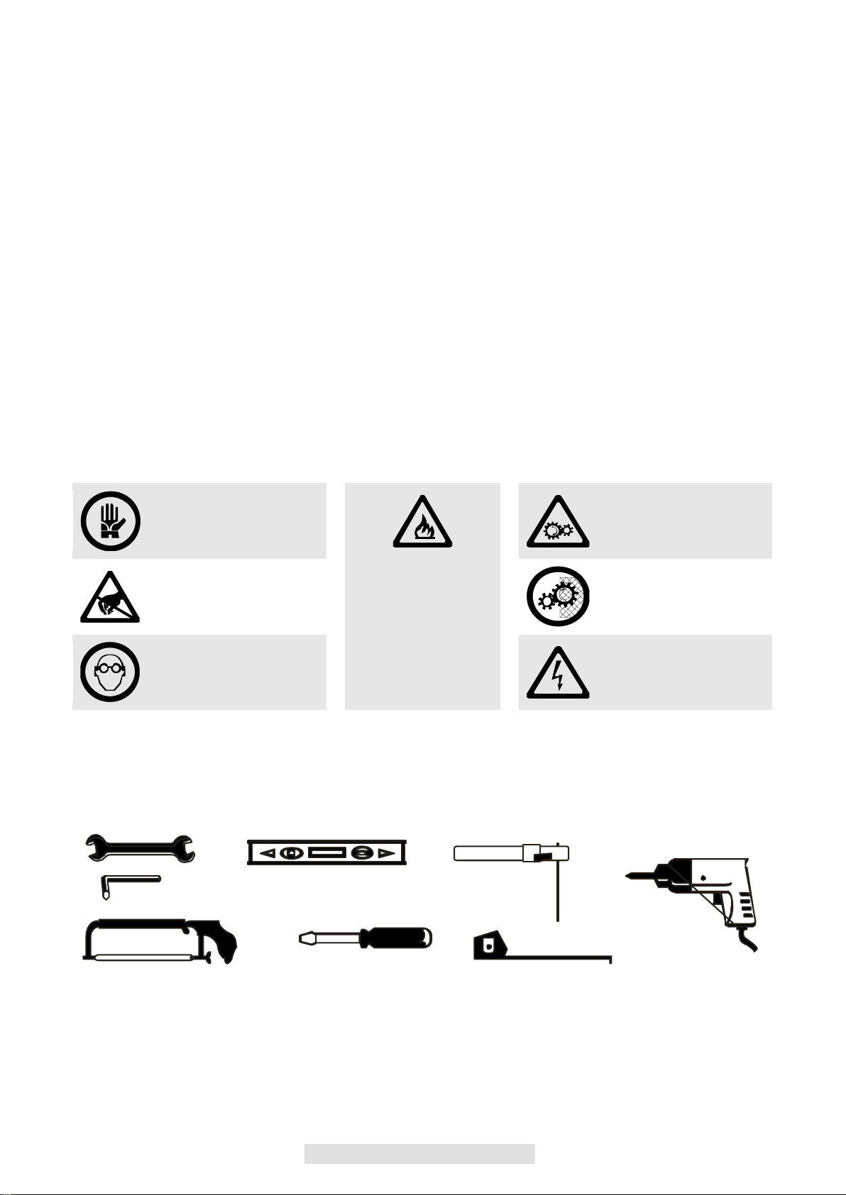
USARE I GUANTI !
ATTENZIONE!
MECCANISMI IN
MOVIMENTO !
ATTENZIONE!
DISTANZA DI
SICUREZZA !
ATTENZIONE!
NON INSTALLARE
L’AUTOMAZIONE IN
AMBIENTI SATURI
DI MISCELE
ESPLOSIVE!
MANTENERE
CARTER DI
PROTEZIONE !
USARE OCCHIALI
PER SALDATURA !
ATTENZIONE!
SHOCK ELETTRICO!
ATTREZZATURA
Per l’installazione dell’automazione è necessaria la seguente attrezzatura: chiavi, cacciavite, metro, bolla,
sega, trapano, saldatrice.
5
I
MODELLI E CARATTERISTICHE
900CT-380
900CT-381
900CT-380E
900CT-381E
Centrale di comando per 1 motore 400Vac/230Vac completa di sistema di
rallentamento e freno per motore scorrevole o portoni sezionali industriali,
predisposizione per scheda radio, fornita con box plastico
Centrale di comando per 1 motore 400Vac/230Vac completa di sistema di
rallentamento e freno per motore scorrevole o portoni sezionali industriali,
predisposizione per scheda radio, fornita con box plastico e pulsanti di comando
Centrale di comando per 1 motore 400Vac/230Vac per motore scorrevole o portoni
sezionali industriali, predisposizione per scheda radio, fornita con box plastico
Centrale di comando per 1 motore 400Vac/230Vac per motore scorrevole o portoni
sezionali industriali, predisposizione per scheda radio, fornita con box plastico e
pulsanti comando
DATI TECNICI
CT-380
ALIMENTAZIONE
400 o 230Vac/50Hz
CARICO MAX MOTORE
2000 W
USCITA ALIMENTAZIONE ACCESSORI
24Vac 15W
TEMPO LAVORO
0-120sec
TEMPO PAUSA
0-120sec
TEMPERATURA DI FUNZIONAMENTO
-20°C/+70°C
GRADO DI PROTEZIONE
IP56
E’ opportuno leggere attentamente le istruzioni prima di eseguire l’installazione.
La non osservanza delle suddette istruzioni, l’uso improprio o un errore di
collegamento potrebbe pregiudicare la sicurezza o il corretto funzionamento del
dispositivo, e quindi dell’intero impianto.
Si declina ogni responsabilità per eventuali malfunzionamenti e/o danni dovuti
derivanti dalla loro inosservanza.
La ditta si riserva di apportare modifiche migliorative al prodotto.
6
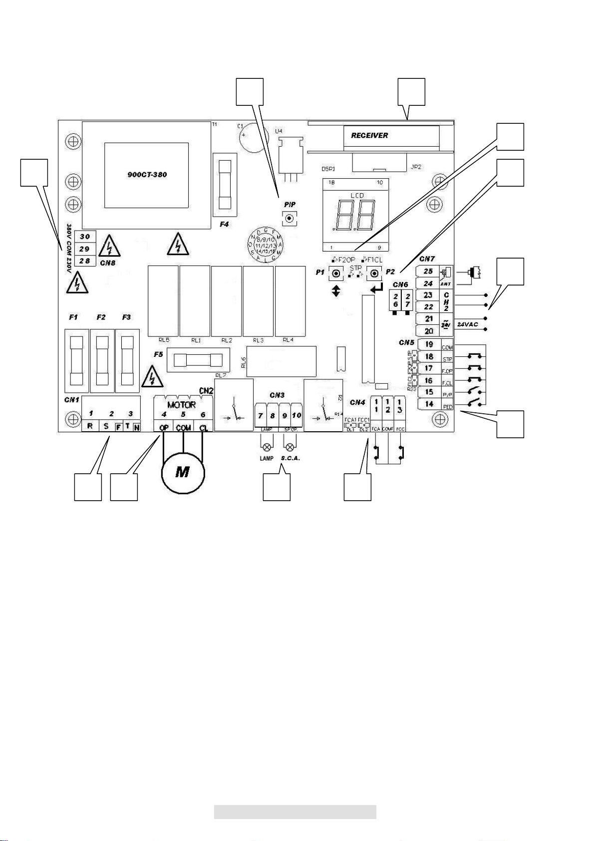
QUADRO D’INSIEME / VERIFICHE PRELIMINARI
DESCRIZIONE
1. Morsettiera collegamenti alimentazione 400Vac(RST)-230Vac(FN)
2. Morsettiera collegamento motore
3. Morsettiera collegamento lampeggiante 230Vac 25W e spia cancello aperto
4. Morsettiera collegamento finecorsa
5. Morsettiera collegamento comandi e sicurezze
6. Morsettiera collegamento alimentazioni accessori 24Vac, secondo canale radio e antenna
7. Connettore per scheda radio ricevente ad innesto
8. Connettore per contatto termica motore
9. Pulsante ENTER per lo scorrimento funzioni per la programmazione / Pulsante UP/DOWN per
variazione / regolazione settaggio funzioni ( vedi tabella )
10. Pulsante passo passo P/P
11. Connettore di selezione funzionamento 400/230Vac
5
7
4
2
1
3
10
11
9
6
8

7
I
La centrale di comando è stata progettata per automatizzare aperture industriali ad 1 motore con
alimentazione trifase 380V. o monofase 230V. con potenza massima di 2.000 W con controlli di sicurezza
attivi e passivi per ottenere una installazione conforme alle vigenti normative di sicurezza.
Grazie ad un sistema BREVETTATO PFC Control presente nei modelli 900CT-380/1 si effettua un
rallentamento programmabile per accostarsi sui finecorsa, in questo modo si può gestire in maniera fluida ed
uniforme tutto il moto dell’anta limitando le forze inerziali anche su cancelli di dimensioni e pesi molto grandi
DIAGNOSI VISIVA STATO SICUREZZE
L’ingresso STOP n° 18 in cui è obbligatorio l’utilizzo di un contatto N.C. deve essere chiuso e i due
puntini dell’LCD NON devono lampeggiare, se lampeggiano vuol dire che il contatto è aperto
L’ingresso FOTO APRE F.OP n°17 in cui è obbligatorio l’utilizzo di un contatto N.C. deve essere
chiuso e il puntino dell’LCD di sinistra F2OP deve essere SPENTO, se risultasse ACCESO FISSO
vuol dire che il contatto è aperto
L’ingresso FOTO CHIUDE F.CL n°16 in cui è obbligatorio l’utilizzo di un contatto N.C. deve essere
chiuso e il puntino dell’LCD di destra F1CL deve essere SPENTO, se risultasse ACCESO FISSO
vuol dire che il contatto è aperto
N.B. I puntini dell’LCD in condizioni di normale utilizzo non devono ne lampeggiare ne essere accesi fissi, si
accendono o lampeggiano nel caso in cui intervenga la sicurezza corrispondente
COLLEGAMENTI ELETTRICI
Per garantire l’incolumità dell’operatore e per prevenire danni ai componenti, mentre si effettuano i
collegamenti, o si innesta la scheda radio, la centralina non deve essere assolutamente alimentata
elettricamente.
Per i cavi di alimentazione, linee motori, linea lampeggianti/luce di cortesia, elettroserratura utilizzare un
cavo con sezione adeguata alla lunghezza del tragitto.(min 1,5 mmq).
Per le alimentazioni ausiliarie i comandi e i contatti di sicurezza una sezione minima di 0.5 mmq.Quando i
cavi di comando sono molto lunghi (oltre 30 m) è consigliabile il disaccoppiamento mediante dei relè presso
la centralina stessa.
Nel caso di intervento di un fusibile, dopo aver rimosso la causa sostituirlo con un altro avente le stesse
caratteristiche. Installare i vari dispositivi di sicurezza, finecorsa, fotocellule, costa sensibile, pulsante di stop.
Se uno o più dispositivi di sicurezza non vengono installati devono essere cortocircuitati relativi morsetti con
il comune comandi.
Tutti i contatti N.C. Abbinati ad uno stesso ingresso devono essere collegati in serie.
Tutti i contatti N.A. abbinati ad uno stesso ingresso devono essere collegati in parallelo.
Prevedere elementi di disconnessione nella rete di alimentazione su posto accessibile.
Per l’alimentazione della centralina è previsto l’inserimento di un SEZIONATORE esterno (non in dotazione)
indipendente e correttamente dimensionato.
- Il CN1 è dedicato al collegamento delle alimentazioni della scheda :
con alimentazione trifase 400Vac utilizzare RST
con alimentazione monofase 230Vac connettere F N
- Collegamento del Motore : Mors. N.4 apertura,N.6 chiusura e N.5 comune
- Collegamento finecorsa motore :N.11(finecorsa apertura) N.13(finecorsa chiusura)
-Collegamento comune finecorsa motori N.12
N.B. i led corrispondenti ai finecorsa sono ACCESI quando non viene interessato il finecorsa relativo,
se non si utilizzano i finecorsa PONTICELLARE OBBLIGATORIAMENTE gli stessi sul morsetto COMF
N.12
- Funzione Pedonale PED :Collegato tra il Mors.N.14 ed il Mors. N.19 Contatto N.A. Normalmente Aperto
E' un comando di apertura che nel caso sia attivato andrà ad aprire parzialmente l’anta (50%della
corsa totale)
-Funzionamento Passo /Passo P/P:
Collegato tra il Mors. N.15 ed il Mors. N.19 Contatto N.A. Normalmente Aperto
Ingresso di comando Apre/Chiude o Apre/Stop/Chiude in base alla selezione del Parametro D
- Funzione Fotocellula Close F.CH :
Collegata tra il Mors. N.16 ed il Mors. N.19 Contatto N.C. Normalmente Chiuso
Tale ingresso viene considerato una sicurezza, il contatto può essere interrotto in qualsiasi momento
durante la chiusura dell’automazione provocando l’immediato blocco del moto invertendo il senso di
marcia

8
- Funzione Fotocellula Open F.OP :
Collegata tra il Mors. N.17 ed il Mors. N.19 Contatto N.C. Normalmente Chiuso
Tale ingresso viene considerato una sicurezza, il contatto può essere interrotto in qualsiasi momento
durante l’apertura dell’automazione provocando l’immediato blocco del moto, l’automazione continuerà
l’apertura al ripristino del contatto.
- Funzionamento Stop STP :
Collegato tra il Mors. N.18 ed il Mors. N.19 Contatto Normalmente Chiuso N.C. Tale ingresso viene
considerato una sicurezza il contatto può essere interrotto in qualsiasi momento bloccando
immediatamente l'automazione disabilitando qualsiasi funzione compresa la Chiusura Automatica
- Collegamento alimentazione accessori 24Vac 7watts tra il Mors. N.20 e N.21 max
- Collegamento 2° canale radio (solo se si utilizza ricevitore innesto 2canali) tra il Mors. N.22 e N.23
- Collegamento antenna : tra il Mors. N.24 (calza) e N.25 (segnale)
- Collegamento sensore termico : tra il Mors. N.26 e N.27 si collega il sensore termico contatto N.C.
proveniente dal motore, in caso di intervento si abilita solo la prima apertura di sicurezza, l’automazione
NON chiuderà fino al ritorno della temperatura di normale esercizio
NB:in caso di non utilizzo si richiede di cortocircuitare il contatto
- Selezione tensione di funzionamento :TRIFASE 400Vac tra N.30 e N.29, MONOFASE 230Vac
tra N.28 e N.29
PROGRAMMAZIONE
La grande affidabilità del sistema e l’alta concentrazione delle funzioni che vengono gestite da un
microcontrollore fanno si che il sistema possa calcolarsi tutti i parametri di rallentamento ed il tempo di
lavoro autonomamente senza nessuna programmazione particolare da parte dell’installatore.
La centrale viene già fornita con una programmazione base che vi permette di avere già i parametri
fondamentali selezionati, si richiede di effettuare solamente la seguente procedura di prima attivazione :
Sbloccare il motore meccanicamente tramite lo sportellino di sblocco e verificare l’esatto
collegamento dei finecorsa in base a l’apertura ed alla chiusura dell’anta, il led corrispondente al
finecorsa interessato deve SPEGNERSI con il finecorsa attivato
Chiudere manualmente l’anta, effettuare ora un impulso di P/P premendo il pulsante relativo; la
prima manovra che deve effettuare l’anta è una APERTURA , se così non fosse togliere
alimentazione all’impianto in modo da invertire l’apre 4 con il chiude 6
Durante la APERTURA sul display si visualizza OP
Durante la CHIUSURA sul display si visualizza CL
Se si è selezionato il funzionamento Automatico visualizza TC nel tempo di pausa
Con automazione chiusa visualizza - -
Se si visualizza ST ( stop )vuol dire che si è abilitata la funzione UOMO PRESENTE e non si
terminato il ciclo di apertura o chiusura completa
Tramite un nuovo comando di P/P verificare che si effettui l’apertura completa dell’anta sino al
finecorsa, a questo punto ripremere il pulsante P/P e verificare la completa chiusura dell’anta sino al
finecorsa .
Dopo aver verificato l’esatto funzionamento di apertura e chiusura completa possiamo andare ad
abilitare il rallentamento in base alla percentuale voluta ( Par. E ) e la Forza motore massima
( Par.L )
N.B. ad ogni variazione di qualsiasi parametro la centrale effettua al primo impulso di start l’apprendimento
del tempo di lavoro da cancello chiuso ad aperto tra i due finecorsa, solo dopo questa manovra potremo
vedere il rallentamento se esso è stato abilitato

9
I
FUNZIONI DI PROGRAMMAZIONE
Si accede al menu dei parametri mantenendo premuto i pulsante P2 ENTER finche appare il primo
parametro C, premendo consecutivamente il pulsante ENTER (P2) si avanza con il menù parametri, per la
variazione del parametro premere il pulsante ↕ UP/DOWN (P1)
NB: funzioni E/F/L/R presenti solo su versioni 900CT-380/900CT-381
FUNZIONI \ VALORI
0
1
2
3
4
5
6
7
8
9
10
c
CHIUSURA
AUTOMATICA (secondi)
NO
5
10
15
20
25
30
40
80
120
d
COMANDO PASSO
PASSO P/P
Apre
Stop
chiude
Apre
Chiude
Attivando la funzione P/P si evita il passaggio dell’automazione nello stato di
stop;ricordiamo che la funzione abilitata può essere critica per automazioni
con grandi inerzie
E
%RALLENTAMENTO
NO
10%
20%
30%
Attivando la funzione Rallentamento negli ultimi secondi di
funzionamento dell’automazione la centrale comanda i
motori a velocità ridotta in base alla %scelta
F
ELETTROFRENO
NO
SI
Attivando la funzione Elettrofreno tramite il parametro F,si riesce a impedire
che un cancello pesante,in seguito ad un comando o un intervento di una
sicurezza, a causa dell’inerzia continui il movimento per qualche secondo
invece di bloccarsi immediatamente
H
CONDOMINIALE(SOLO
APRE)
NO
SI
Attivando la funzione condominiale facciamo in modo che il primo impulso di
P/P apre ed accetta solo la riapertura durante la chiusura
L
FORZA MOTORE
100%
Max
10% Min
20%
30%
40%
50%
60%
70%
80%
90%
o
CHIUDE DOPO
TRANSITO
NO
SI
Attivando la funzione Chiude dopo Transito con chiusura automatica inserita
facciamo in modo di far chiudere l’automazione nel tempo più breve possibile
senza attendere la richiusura automatica
P
TIMER/SPIRA
MAGNETICA SU P/P
NO
SI
Attivando la funzione Timer/Spira magnetica tramite il parametro P dopo aver
terminato l’apertura totale se si mantiene chiuso il contatto di P/P N.15 si
blocca il tempo di chiusura automatica in modo che il cancello non si chiuda
mai sino alla nuova apertura del contatto di P/P, nel caso intervenissero vari
impulsi di P/P durante il tempo di attesa della chiusura automatica il tempo
viene continuamente riazzerato
r
TEMPO PARTENZA
RALLENTATA SOFT
START
NO
SI
Attivando la funzione Soft Start facciamo in modo che nei primi secondi di
movimento dell’automazione la centrale comanda il motore a velocità ridotta
per avere una partenza più dolce
T
TIPOLOGIA
RALLENTAMENTO
2500Kg
(SC-240)
4000Kg
(SC-400)
Seleziona il tipo di rallentamento in base al cancello
U
UOMO PRESENTE
NO
SI
Attivando la funzione uomo presente tramite il parametro U si ha la possibilità
di far aprire l’automazione fintanto che il contatto di P/P N.15 è chiuso e far
chiudere l’automazione fintanto che il contatto PED n.14 è chiuso ;al rilascio
dei due contatti l’automazione si posiziona in STOP
y
PRELAMPEGGIO
NO
1sec
2sec
4sec
Attivando la funzione Prelampeggio prima di ogni
movimento il lampeggiante viene attivato per il tempo
selezionato
N.b.: ogni variazione di funzione deve essere effettuata con l’ automazione chiusa
Alla fine della visualizzazione dei parametri si accede al contatore manovre totali che vengono visualizzate in
2 videate differenti dove le migliaia si evidenziano con l’accensione del puntino:Se si vuole azzerare tale
contatore mantenere premuto assieme il pulsante P1 e P2 (ENTER/UP-DOWN) finchè non si visualizza
0000
N.B. Se si accende il puntino dell’LCD di sinistra vuol dire che sono state passate le 10.000 manovre che
andranno aggiunte al valore visualizzato.
Per uscire dalla visualizzazione parametri premere il tasto ENTER più volte fino a visualizzare la condizione
di automazione chiusa - - ( due trattini )

10
REGOLAZIONE FORZA MOTORI (SOLO PER 900CT-380/381)
Dopo uno spunto di 1,5 Sec. si inserisce il controllo di Forza elettronica in cui si parzializza la tensione di
alimentazione regolandone il valore tramite il parametro L
N.B. riferirsi per i carichi di spinta massima alle normative vigenti.
CONNETTORE RADIO
La centrale CT-101 è compatibile con i seguenti ricevitori Key automation della serie MEMO ad innesto:
900RXI-41 / 900RXI-41R / 900RXI-42 / 900RXI-42R
AVVERTENZE FINALI
L'installazione dell'automazione deve essere eseguita a regola d'arte da personale qualificato avente i
requisiti di legge e fatta in conformità della direttiva macchine 98/37/CE e alle normative EN13241-1,
EN 12453 e EN 12445.
Verificare la solidità delle strutture esistenti (colonne, cerniere, ante) in relazione alle forze sviluppate
dal motore.
Verificare che vi siano dei fermi meccanici di adeguata robustezza a fine apertura e fine chiusura delle
ante.
Fare un'analisi dei rischi dell'automazione e di conseguenza adottare le sicurezze e le segnalazioni
necessarie.
Installare i comandi (ad esempio il selettore a chiave) in modo che l'utilizzatore non si trovi in una zona
pericolosa.
Terminata l'installazione provare più volte i dispositivi di sicurezza, segnalazione e di sblocco
dell'automazione.
Applicare sull'automazione l'etichetta o la targhetta CE contenenti le informazioni di pericolo e i dati di
identificazione.
Consegnare all'utilizzatore finale le istruzioni d'uso, le avvertenze per la sicurezza e la dichiarazione
CE di conformità.
Accertarsi che l'utilizzatore abbia compreso il corretto funzionamento automatico, manuale e di
emergenza dell'automazione.
Informare l'utilizzatore per iscritto (ad esempio nelle istruzioni d'uso) dell' eventuale presenza di rischi
residui non protetti e dell'uso improprio prevedibile.
Predisporre un piano di manutenzione dell'impianto (almeno ogni 6 mesi per le sicurezze) riportando
su di un apposito registro gli interventi eseguiti.
Conservare il presente manuale di istruzioni per future consultazioni.
La ditta KEY Automation Srl si riserva la facoltà insindacabile di apportare, in qualsiasi momento, le
modifiche che si rendessero necessarie ai fini di un miglioramento estetico e/o funzionale.
SMALTIMENTO
Questo prodotto è formato da vari componenti che potrebbero a loro volta contenere sostanze inquinanti.
Non disperdere nell'ambiente! Informarsi sul sistema di riciclaggio o smaltimento del prodotto attenendosi
alle norme di legge vigenti a livello locale.

11
GB
K
INDEX
SAFETY............................................................................................................................................................12
EQUIPMENT ....................................................................................................................................................12
MODELS AND CHARACTERISTICS..............................................................................................................13
OVERALL VIEW / PRELIMINARY CHECKS..................................................................................................14
ELECTRICAL CONNECTIONS .......................................................................................................................15
PROGRAMMING..............................................................................................................................................16
PROGRAMMING FUNCTIONS .......................................................................................................................17
RADIO CONNECTOR......................................................................................................................................18
DISPOSAL .......................................................................................................................................................18
NOTES..............................................................................................................................................................51
THIS BOOKLET IS TO BE USED ONLY BY THE INSTALLER
Installation must be carried out only by professionally qualified personnel in compliance with current legal
requirements.
12
SAFETY
Congratulations on your choice of our product.
This manual will aid you in installing your reduction gear.
As you read through it, you will find not only explanations on the operation of the reduction gear, but also on
safety standards that you must comply with for perfect operation and maximum safety.
To prevent damage to your unit and to avoid injury to yourself or others, before installing the reduction gear
and its components, carefully read all of the following information on safety standards.
Keep this information so that anyone who will be using the unit can refer to it.
No liability shall be accepted for the consequences of failure to comply with the precautions provided.
! If the unit malfunctions, shut it off immediately.
! When making repairs, make sure the electrical supply is disconnected.
! Do not attempt to disassemble the unit if you are not an authorized installer.
! Do not expose to flames or sources of heat. Do not immerge in water or other liquids.
! Use suitable power cables.
! Supervise the door when it is moving. Keep people away from it until it is completely open or closed.
SAFETY STANDARDS
During installation and use of this automation, carefully follow these safety standards:
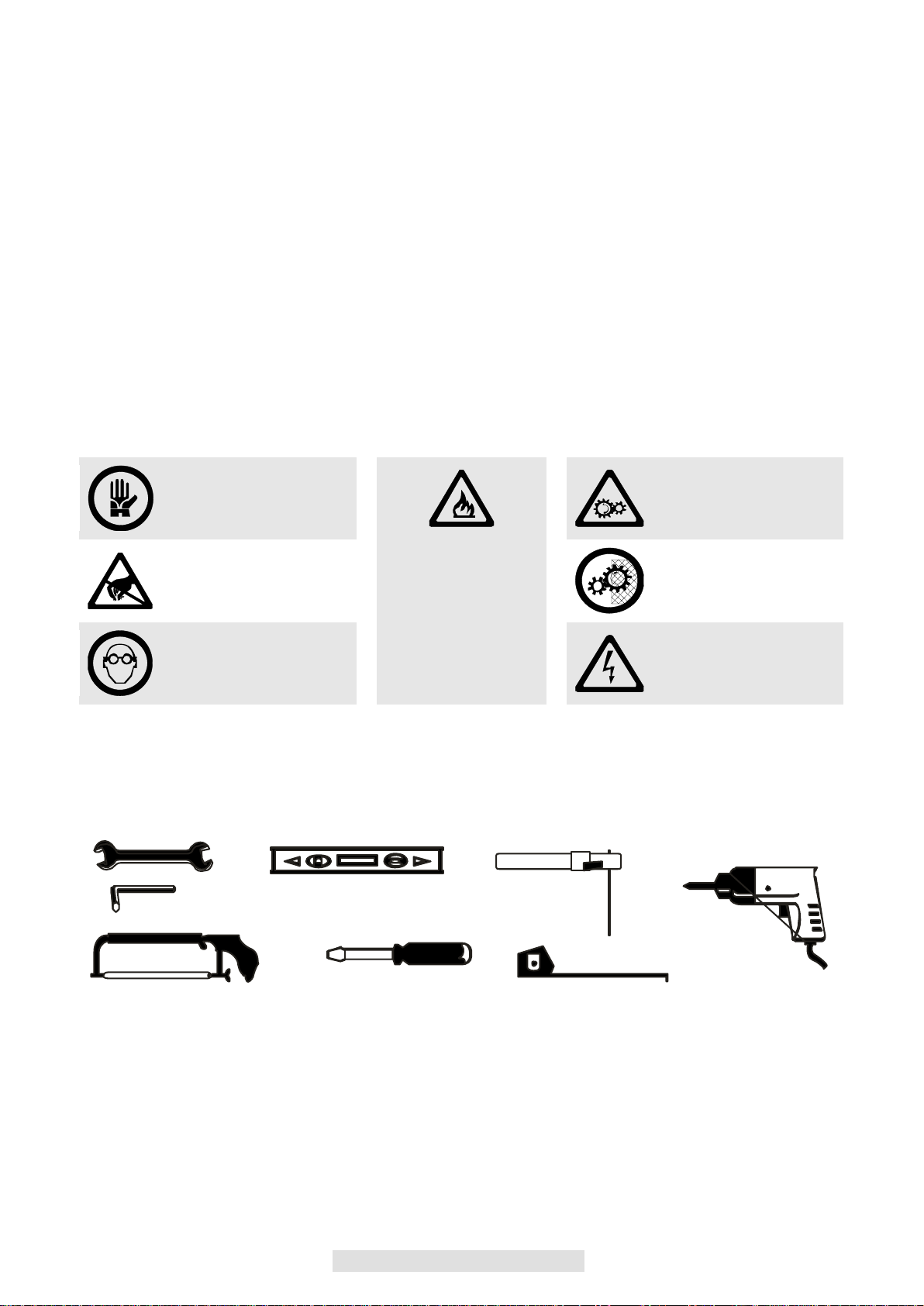
USE GLOVES!
ATTENTION!
MECHANISMS IN
MOVEMENT!
ATTENTION!
SAFE DISTANCE
ATTENTION!
DO NOT INSTALL
THE AUTOMATION
IN ENVIRONMENTS
THAT ARE
SATURATED WITH
EXPLOSIVE
MIXTURES!
LEAVE GUARD IN
PLACE!
USE WELDING
GOGGLES!
ATTENTION!
ELECTRICAL SHOCK!
EQUIPMENT
To install the automation, you will need the following equipment: wrenches, screwdrivers, tape measure,
level, saw, drill, welder.

13
GB
K
MODELS AND CHARACTERISTICS
900CT-380
900CT-381
900CT-380E
900CT-381E
Control unit for 1 motor 400V AC/230V AC complete with deceleration system and
brake for sliding motor or industrial sectional doors, set up for radio card, supplied
with plastic box
Control unit for 1 motor 400V AC/230V AC complete with deceleration system and
brake for sliding motor or industrial sectional doors, set up for radio card, supplied
with plastic box and control buttons
Control unit for 1 motor 400V AC/230V AC for sliding motor or industrial sectional
doors, set up for radio card, supplied with plastic box
Control unit for 1 motor 400V AC/230V AC for sliding motor or industrial sectional
doors, set up for radio card, supplied with plastic box and control buttons
TECHNICAL DATA
CT-380
POWER SUPPLY
400 or 230V AC/50Hz
MAX. MOTOR LOAD
2000 W
ACCESSORIES POWER SUPPLY OUTPUT
24V AC 15W
WORKING TIME
0-120sec
PAUSE TIME
0-120sec
OPERATING TEMPERATURE
-20°C/+70°C
DEGREE OF PROTECTION
IP56
It is advisable to read the instructions carefully before you start installation.
Failure to comply with these instructions, improper use or incorrect connection
may compromise the safety or correct operation of the device and hence of the
entire system.
No liability shall be accepted for any malfunctions and/or damage due to failure to
comply with the instructions.
The company reserves the right to make improvements to the products.

14
OVERALL VIEW / PRELIMINARY CHECKS
DESCRIPTION
1. Power supply connection terminal board 400V AC(RST)-230V AC (FN)
2. Motor connection terminal board
3. Flasher connection terminal board 230V AC 25W and gate open indicator light
4. Limit switch connection terminal board
5. Controls and safety devices connection terminal board
6. Terminal board for connection of 24 V AC accessories power supply and second radio channel and
antenna
7. Connector for snap-in radio receiving card
8. Connector for motor thermal contact
9. ENTER button to scroll functions for programming / UP/DOWN button for variation / adjustment of
functions settings (see table)
10. Step/step button P/P
11. Connector for selection of operation 400/230V AC
5
7
4
2
1
3
10
11
9
6
8

15
GB
K
The control unit was designed for the automation of industrial openings with 1 motor with tri-phase power
supply 380V. or single phase 230V. with maximum power of 2,000 W with active and passive safety controls
to obtain installation that is compliant with current safety standards.
Thanks to the patented PFC Control system in the models 900CT-380/1, programmable deceleration is
performed to stop at the limit switches. This provides fluid and uniform control of all the movement of the
door, limiting inertial forces on especially large and heavy gates
VISUAL DIAGNOSIS OF STATUS OF SAFETIES
STOP input no. 18 in which the use of an N.C. contact is compulsory must be closed and the two
points of the LCD must not flash. If they flash, it means that the contact is open
The input PHOTO OPEN F.OP no. 17, which requires the use of an NC contact, must be closed and
the F2OP point of the LCD on the left must be OFF. If it is on STEADY it means that the contact is
open
The input PHOTO CLOSE F.CL no. 16, which requires the use of an NC contact, must be closed
and the F1CL point of the LCD on the right must be OFF. If it is on STEADY it means that the
contact is open
N.B. In normal use, the points of the LCD must not flash or be on steady. They flash or stay on if the
corresponding safety is activated.
ELECTRICAL CONNECTIONS
To ensure operator safety and to prevent damage to the components while connections are being made, or
when the radio card is being inserted, the control unit absolutely must not be powered on.
For power cords, motor lines, flasher/courtesy light line, and electric lock, use a cable with a cross-section
that is suitable for the length (minimum 1.5 mm2).
For auxiliary power supplies, controls and safety contacts a minimum section of 0.5 mm2. When the control
cables are very long (more than 30 m), de-coupling is suggested using relays at the control unit.
If a fuse trips, after removing the cause, replace it with another one of the same type. Install the various
safety devices, limit switches, photocells, sensitive rib, stop button.
If one or more of the safety devices are not installed, the corresponding terminals must be short circuited
with the controls common.
All contacts N.C. Assigned to the same input must be connected in series.
All contacts N.O. Assigned to the same input must be connected in parallel.
Provide disconnecting devices in the power supply network in accessible places.
For the power supply of the control unit, there must be an external disconnecting switch (not included),
independent and properly sized.
- CN1 is dedicated to the connection of the power supply of the board:
with tri-phase power supply 400V AC use RST
with single-phase power supply 230V AC connect F N
- Connection of motor: Term. N.4 opening, N.6 closure and N.5 common
- Motor limit switch connection: N.11 (limit switch opening) N.13 (limit switch closure)
-Motors limit switch common connection N.12
N.B. The LEDs that correspond to the limit switches are ON when the relative limit switch is not
involved, if you do not use the limit switch they must be jumper connected to the COMF terminal
N.12
- PED pedestrian function: Connected between Term. N.14 and Term. N.19 Contact N.O. Normally open
It is an opening command which when activated will partially open the door (50% of total travel)
-Step/step operation:
Connected between Term. N.15 and Term. N.19 Contact N.O.
Control input open/close or open/stop/close based on selection of parameter D
- Close Photocell Function F.CH :
Connected between Term. N.16 and Term. N.19 Contact N.C.Normally Closed
This input is considered a safety, the contact can be interrupted at any time during closing of the
automation causing an immediate stop in movement and reversing the direction of movement

16
- Open Photocell Function F.CH :
Connected between Term. N.17 and Term. 19 Contact N.C. Normally closed
This input is considered a safety, the contact can be interrupted at any time during opening by the
automation causing an immediate stop in movement, the automation will continue until the contact is
restored.
Stop function STP :
Connected to Term. N.18 and Term. N.19 Contact Normally Open N.C. This input is considered a safety
the contact can be interrupted at any time immediately stopping the automation disabling any function
including automatic closing.
- Accessory power supply connection 24V AC 7 watts between Term. N.20 and N.21 max.
- 2nd radio channel connection (only if using 2-channel radio connector) between terminal N.22 and N.23
- Antenna connection: between Term. N.24 (mesh) and N.25 (signal)
- Thermal sensor connection: between Term. N.26 and N.27, the N.C. contact thermal sensor is
connected from the motor. In the event of intervention only the first safety opening will be enabled. The
automation will NOT close until the normal operating temperature is restored
NB: if not used, it is necessary to short-circuit the contact
-Selection of operating voltage: TRI-PHASE 400V AC between N.30 and N.29, SINGLE-PHASE 230V AC
between N.28 and N.29
PROGRAMMING
The great reliability of the system and the high concentration of the functions are managed by a micro-
controller so that the system can autonomously calculate all deceleration parameters and the working time
with no special programming by the installer.
The unit is equipped with basic programming that will provide you with the fundamental selected
parameters. Only the following procedure is required for first start-up:
Release the motor mechanically through the release panel and verify the precise connection of the
stops based on the opening and closing of the door. The LED corresponding to the affected stop
must SWITCH OFF with an activated stop
Close the door manually, carry out a P/P impulse by pressing the corresponding button; the first
action performed by the door is an OPENING. If this is not the case remove power from the system
so as to replace the opening with the closing
During OPENING the display will show OP
During CLOSING the display will show CL
If you have selected Automatic operation, TC will be shown in the pause time
With the automation closed, -- will be shown.
If ST (stop) is shown, it means that the MAN PRESENT function is enabled and
the complete opening or closing cycle has not ended.
By using a new P/P command check that the complete opening of the door is carried out up to the
stop. At this point press the P/P button again and check the complete closing of the door up to the
stop.
After having verified the correct complete opening and closing enable the deceleration based on the
desired percentage ( Par. E ) and the maximum motor force ( Par.L )
N.B. with each variation of any parameter the control unit will, at the first start impulse, verify the working
time of the closed and open gate between the two stops. Only once this is carried out the enabling of the
deceleration can be verified

17
GB
K
PROGRAMMING FUNCTIONS
Access the parameter menu by holding the P2 ENTER button until the first parameter, C, appears. Press the
ENTER button (P2) repeatedly to advance through the parameters menu. To change the parameter press ↕
UP/DOWN (P1)
NB: Functions E/F/L/R are present only on versions 900CT-380/900CT-381
FUNCTIONS \ VALUES
0
1
2
3
4
5
6
7
8
9
10
c
AUTOMATIC CLOSURE
(seconds)
NO
5
10
15
20
25
30
40
80
120
d
STEP BY STEP
COMMAND P/P
Open
Stop
close
Open
Close
By activating the step/step function, you avoid passage of the
automation in the stop state. The enabled function may be critical for
automations with high inertia.
E
%DECELERATION
NO
10%
20%
30%
When the deceleration function is activated in the last
seconds of operation of the automation, the control unit
slows the motors based on the selected %.
F
ELECTROBRAKE
NO
YES
By activating the electrobrake function through the F parameter, a heavy
gate is prevented from continuing its movement, due to its inertia, for a
few seconds instead of stopping it instantenously following a command
or a safety action
H
CONDOMINIUM (OPEN
ONLY)
NO
YES
Activate the condominium function so that the first step/step impulse
opens and accepts only re-opening during closing
L
MOTOR FORCE
100%
Max
10%
Min
20%
30%
40%
50%
60%
70%
80%
90%
o
CLOSE AFTER TRANSIT
NO
YES
When you activate the Close After Transit function with automatic
closure activated, the automation is closed in the shortest time possible
without waiting for automatic re-closing.
P
TIMER/MAGNETIC COIL
ON STEP/STEP
NO
YES
When you activate the function Timer / Magnetic Coil via parameter P
after terminating total opening if step/step contact N.15 is kept closed the
automatic closing time is locked so that the gate never closes until the
step/step contact is opened again, if there are several step/step impulses
during the standby time for automatic closing the time will be
continuously reset
r
SOFT START DELAYED
START TIME
NO
YES
When you activate the Soft Start function, during the first seconds of
movement of the automation the control unit keeps the motor at reduced
speed for a softer start.
T
TYPE OF SLOWING
DOWN
2500Kg
(SC-240)
4000Kg
(SC-400)
Select the type of slowdown on the basis of
the gate
U
MAN PRESENT
NO
YES
When you activate the Man Present function via parameter U, you can
open the automation until step/step contact N.15 is closed and close the
automation until contact PED n.14 is closed; when the two contacts are
released the automation goes to STOP position.
y
PRE-FLASHING
NO
1sec
2sec
4sec
When the pre-flashing function is activated, before any
movement the flasher is activated for the selected time
N.B.: any variation in function must be made with the automation closed
Once the parameters have been displayed, the total manoeuvres counter are shown in two different screens,
where the thousand units are indicated by the lighting up of the point. To reset this counter, simultaneously
press and hold buttons P1 and P2 (ENTER/UP-DOWN) until 0000 is displayed
N.B. If the point of the LCD on the left lights up, it means that 10,000 manoeuvres have been exceeded,
which must be added to the value shown.
To exit parameter display, press ENTER several times until automatic closure condition is shown ( -- two
dashes).

18
ADJUSTMENT OF FORCE OF MOTORS (ONLY FOR 900CT-380/381)
After a breakaway of 1.5 seconds, the electronic force control activates which distributes the power supply,
adjusting the value by means of parameter L.
N.B. for maximum thrust loads refer to current standards.
RADIO CONNECTOR
The CT-101 control unit is compatible with the following Keyautomation receivers of the MEMO snap-in
series:
900RXI-41 / 900RXI-41R / 900RXI-42 / 900RXI-42R
FINAL WARNINGS
The installation of the automation must be performed properly by qualified personnel in possession of
legal requirements and in compliance with machine directive 98/37/CE and standards EN13241-1, EN
12453 and EN 12445.
Check the solidity of existing structures (columns, hinges, doors) in relation to the force generated by
the motor.
Check that there are suitably sturdy mechanical stops at the end of opening and closing travel of the
doors.
Analyze the risks of the automation and adopt necessary safety measures and warnings.
install controls (such as the key selector) so that the user is not in a hazardous position.
Upon completion of installation, check the safety devices several times, as well as those for signalling
and automation release.
Provide the automation with the EC label or tag that contains the danger information and identification
data.
Give the final user the instructions for use, safety warnings and the EC declaration of conformity.
Make sure the user understands proper automatic, manual and emergency operation of the
automation.
Inform the user in writing (for example in the instructions for use) of any unprotected residual risks and
foreseeable improper use.
Provide a maintenance schedule for the system (at least every 6 months for the safeties) with an
appropriate register of work performed.
Keep this instruction manual for future reference.
KEY Automation Srl reserves the right to make, at any time, any modifications which may be required
to improve appearance and/or operation.
DISPOSAL
This product is composed of various components which may in turn contain pollutants. Do not dispose of it in
the environment! Find out about the method for recycling or disposing of the product in compliance with
current local laws.

19
F
SOMMAIRE
SÉCURITÉ........................................................................................................................................................20
OUTILS.............................................................................................................................................................20
MODÈLES ET CARACTÉRISTIQUES ............................................................................................................21
TABLEAU D'ENSEMBLE / CONTRÔLES PRÉLIMINAIRES.........................................................................22
BRANCHEMENTS ÉLECTRIQUES ................................................................................................................23
PROGRAMMATION.........................................................................................................................................24
FONCTIONS DE PROGRAMMATION ............................................................................................................25
CONNECTEUR RADIO....................................................................................................................................26
MISE AU REBUT .............................................................................................................................................26
NOTES..............................................................................................................................................................51
CE MANUEL EST EXCLUSIVEMENT DESTINÉ À L'INSTALLATEUR
L’installation ne devra être effectuée que par du personnel professionnellement qualifié et conformément aux
dispositions des normes en vigueur.

20
SÉCURITÉ
Nous vous félicitons de votre choix et de la préférence accordée à nos produits.
Ce manuel est rédigé dans le but de vous aider pour l'installation du motoréducteur.
La lecture du manuel vous fournira des explications non seulement sur les fonctions du motoréducteur, mais
aussi sur les normes de sécurité à garantir pour obtenir toujours un fonctionnement parfait et en toute
sécurité.
Pour prévenir tout risque de dommage au matériel et éviter toute blessure à quiconque, lire intégralement ce
manuel avant d'installer le motoréducteur et ses composants, en prêtant une attention particulière aux
avertissements exposés ci-dessous concernant les normes de sécurité.
Conserver ce manuel de manière à ce que quiconque utilise l'appareil puisse préalablement le consulter.
La société décline toute responsabilité dérivant du non-respect des précautions indiquées.
! En cas de mauvais fonctionnement, éteindre immédiatement l'appareil.
! En cas de réparation, vérifier d'avoir coupé le courant du réseau électrique.
! Ne pas essayer de démonter l'appareil, seuls les installateurs agréés y sont autorisés.
! Ne pas exposer l'appareil aux flammes ni à d'autres sources de chaleur, ni le plonger dans l'eau ou dans
d'autres liquides.
! Utiliser des câbles d'alimentation appropriés.
! Surveiller le mouvement de la porte et éloigner toute personne tant que la porte n'est pas complètement
ouverte ou fermée.
NORMES DE SÉCURITÉ
Pendant l’installation et l’utilisation de l’automatisme, suivre scrupuleusement les normes de sécurité
suivantes :
PORTER DES GANTS
!
DANGER !
MÉCANISMES EN
MOUVEMENT !
DANGER !
DISTANCE DE
SÉCURITÉ !
DANGER !
NE PAS INSTALLER
L’AUTOMATISME
DANS DES LIEUX
SATURÉS DE
MÉLANGES
EXPLOSIFS !
LES CARTERS DE
PROTECTION
DOIVENT TOUJOURS
ÊTRE MONTÉS
CORRECTEMENT !
PORTER DES
LUNETTES DE
SOUDEUR !
DANGER !
CHOC ÉLECTRIQUE !
OUTILS
Les outils suivants sont nécessaires pour installer l’automatisme : clés, tournevis, mètre, niveau à bulle, scie,
perceuse, soudeuse.
This manual suits for next models
3
Table of contents
Languages:
Popular Control Unit manuals by other brands

GeoVision
GeoVision GV-IB25 manual

S-products
S-products MP 2-wire series instruction manual

Emerson
Emerson Kunkle Series Operating and safety instructions

UniData Communication Systems
UniData Communication Systems Neon 2000 Family manual

Walvoil
Walvoil DPC130X Service manual

tau
tau 800LL quick start guide


