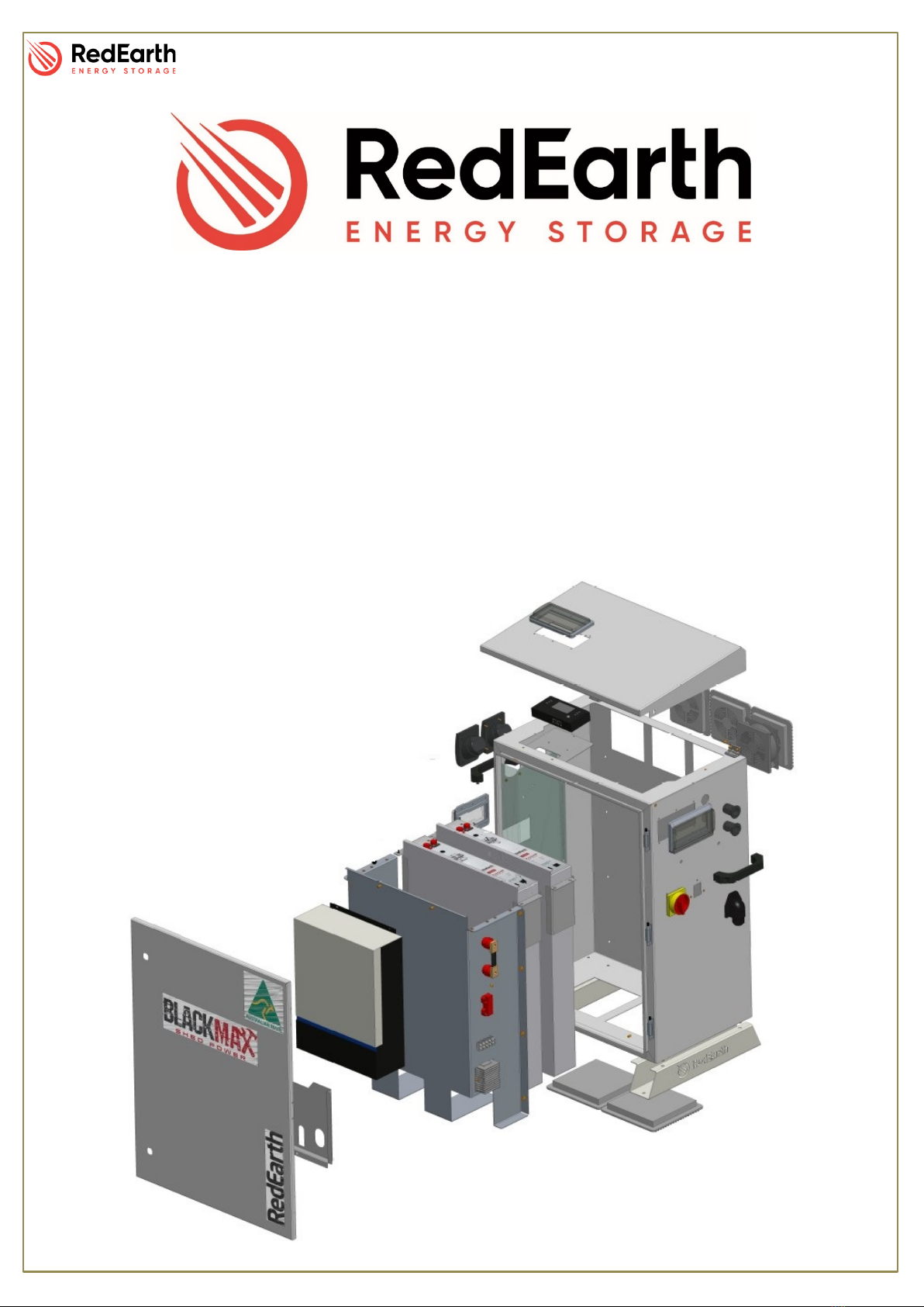
BlackMax – Installation Manual
RE_PROD_0005 Version 1 Page 3 of 21 Issue Date 28/07/2020
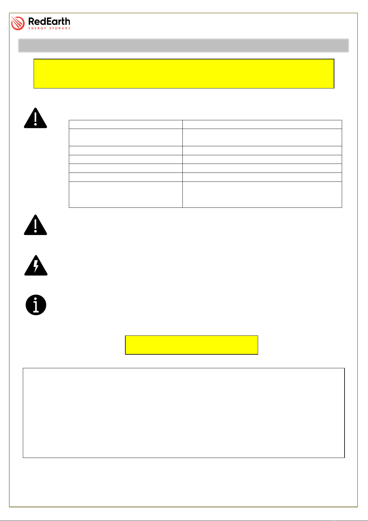
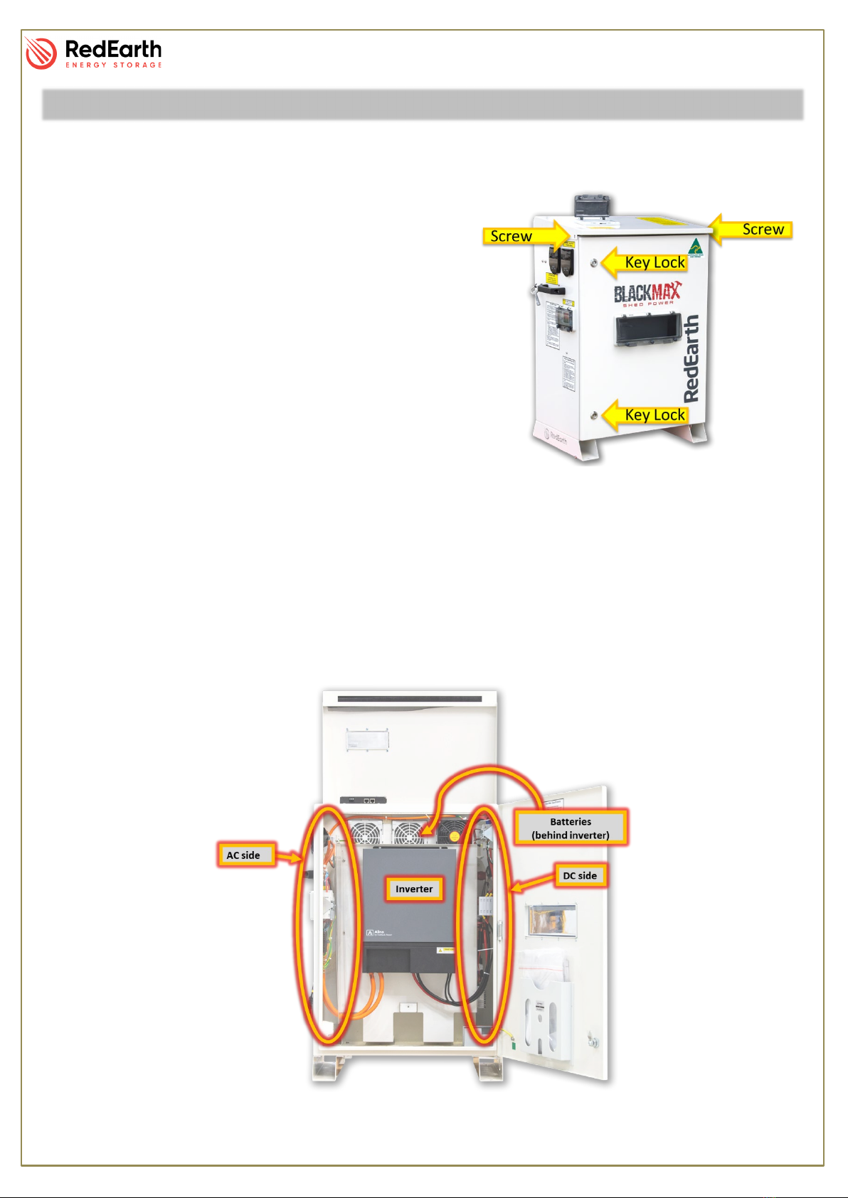
WARNING: Working on the inside of the BlackMax system is restricted to qualified personnel.
RedEarth recommend installation by licensed electricians only.
WARNING: Lithium Battery hazard
The BlackMax must only be installed by suitably qualified personnel who have read
and are familiar with its operation and hazards.
In our efforts towards constant product enhancement, this document is subject to
change at any time. Please visit www.redearth.energy
appropriate and latest version manual.
CAUTION: The battery provided with this system must be charged only by the
AlinoTL inverter Do not attempt to charge the batteries with any other charger device
or connect any devices directly to the DC battery bus.
The wiring diagrams and installation instructions are given as a guide only and
compliance to appropriate standards is the responsibility of the installer. Relevant
standards are listed below:
AS/NZS 5033:2014 (amdt 1&2)
Installation and safety requirements for
photovoltaic (PV) arrays
Stand-alone power systems-Design
Structural design actions-Wind actions
Electrical installations – Selection of cables
Electrical installations-Safety of battery
systems for use with power conversion
equipment
In the advent of fire evacuate the area and call emergency services. A dry agent fire extinguisher should
be readily available and used. DO NOT use water. Evacuate the area and call emergency services. Toxic
gas may be produced if the battery catches fire.
Note: MSDS document is provided with the system and also can be found at www.redearth.energy
Damaged battery
Do not use a damaged battery. Batteries should only be disposed of at an appropriate recycling centre.
Please contact RedEarth for advice.