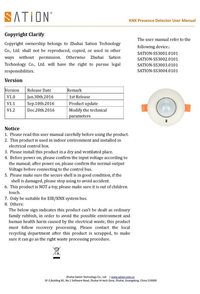
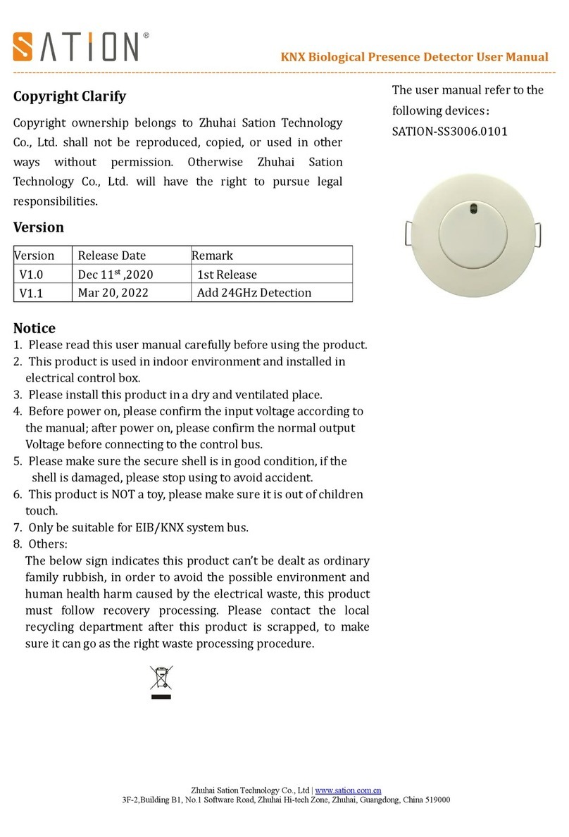
SATION SS3001.1 User manual

1
夺
Technical Manual
SATION Presence Detector
SATION-SS3001.1
SATION-SS3002.1

2
1 Content
1 Content................................................................................................................................................................... 2
2 Overview................................................................................................................................................................ 3
2.1 Overview Devices........................................................................................................................................ 3
2.2 Exemplary circuit diagram........................................................................................................................... 3
2.3 Usage & Areas of use................................................................................................................................... 4
2.4 Detection area...............................................................................................................................................4
2.5 Functions...................................................................................................................................................... 5
2.6 Overview functions..................................................................................................................................... 6
2.7 Starting up................................................................................................................................................... 6
3 Communication objects.......................................................................................................................................... 7
3.1 Overview...................................................................................................................................................... 7
3.2 Default-settings of the communication objects............................................................................................ 7
4 ETS-Parameter....................................................................................................................................................... 9
4.1 General......................................................................................................................................................... 9
4.2 light / HCV................................................................................................................................................. 11
4.2.1 Sensor configuration.........................................................................................................................12
4.2.2 Communication object settings........................................................................................................ 15
4.3 Brightness................................................................................................................................................... 18
4.3.1 Brightness settings............................................................................................................................18
4.3.2 Brightness critical value................................................................................................................... 19
4.4 Calibration brightness value....................................................................................................................... 20
4.4.1 Calibration brightness value............................................................................................................. 20
4.4.2 Approach at Teach-In ......................................................................................................................22
4.5 Master/Slave............................................................................................................................................... 22
4.5.1 Light groups......................................................................................................................................22
4.5.2 HCV Channel................................................................................................................................... 23

3
2 Overview
2.1 Overview Devices
The Manual refer to the following devices :
SATION- SS3001.1 Passive Infrared Detector, 1 sensor
SATION- SS3002.1 Microwave Presence Detector, 1 sensor
Passive Infrared Detector (PIR )or microwave Presence detection, the sensitivity degree on the
programming status (1 Level ~ 10 Level ) , switching options for movement and lightness, separate
communication object for night, Master/Slave function, Standby‐/Orientation light.
2.2 Exemplary Circuit diagram
KNX/EIB Bus
﹣
﹢
Figure 1 : Exemplary Circuit Diagram
KNX

4
2.3 Usage &Areas of use
The SATION Presence Detector switches the light accordingly to the brightness and presence. It can be used
for switching on demand to switch the light economically. Especially in public buildings, but also in rarely used
rooms as bath and WC, the presence detector can be used to minimalize the non‐essential switching periods.
An additional channel transmits informations about presence in the room to other subsections as
Heating‐control, air‐conditioning, ventilation or shutter controlling.So the presence Detector can also be
employed in a subsection comprehensive use.Due to it’s small outline structure,installed in the ceiling is not easy
to be found.
2.4 Detection area
The following figure shows the detection area of the presence detector:
H:2m-4m
W1:4m-6m
W2:6m-8m
Figure 2:Detection area
High :Normal operating range: 2m ~ 4m, Range of sensitivity: 2.5m ~ 3m,recommend: 2.7m;
Angle:Detection angle about 100 °;
Weight 1 :High sensitivity area,range:4m ~ 6m(PIR:sensibility level 10);
Weight 2 :Maximum sensitivity area,range:6m ~ 8m(PIR:sensibility level 10);

5
2.5 Function
The functions of the presence detector are divided in the areas general settings, settings for the light control, the
HCV‐channel, the sending behavior, the calibration for the brightness value and according to the the hardware
type, the constant level light control.
The following menus are shown and can be parametrized further:
General
The general settings are used for the basic settings of the presence detector. The using of the day/night object,
and the presence object as well as the force control release time and a cyclic heartbeat can be configured in
this menu.
Select light groups
One light group and one HVC channel can be activated in this menu.
O Lightgroup 1
The settings for the presence mode can be done here. So the operating mode of the light group, the
sending behavior and a brightness threshold can be adjusted.
O HCV Channel
The Heating‐, Ventilation‐, Clima‐channel is the interace of the presence detector to other subsections.
The HVC‐channel contains of the same options as the light groups.
Brightness
Settings fort he sending of the measured brightness value and a treshold value can be adjusted
Here.
Calibration brightness value
The correction of the measured brightness value can be adjusted by a steady parameter or
via the Teach-In object.

6
2.6 Overview Functions
General settings
general
cyclic heartbeat telegram
force control release time
Day-/Night-object
Light groups
Detector settings
Operating mode adjustable
LED-display adjustable
Follow-Up time adjustable
Brightness threshold adjustable
Blocking object/ Force control object
Sending behavior
Object type adjustable
Polarity adjustable
Dependency of day/night adjustable
seinding filter adjustable
cyclic sending
HCV
Detector settings
Operating mode adjustable
LED-display adjustable
Follow-Up time adjustable
Brightness threshold adjustable
Blocking object/ Force control object
Sending behavior
Object type adjustable
Polarity adjustable
Dependency of day/night adjustable
Sending filter adjustable
Cyclic sending
Brightness value
Sending behavior
At changes
Cyclic sending
Threshold adjustable
Hysteresis adjustable
Object value adjustable
Sending filter adjustable
Calibration
Via parameters
Via Teach-In
Table 1:overview functions

7
2.7 Starting up
After wiring the allocation of the physical address and the parameterization of every channel follow:
(1) Connect the interface with the bus, e.g. MDT USB interface
(2) set bus power up
(3) Press the programming button at the device(red programming LED lights)
(4) Loading of the physical address out of the ETS-Software by using the interface(red LED goes out, as well
this process was completed successful)
(5) Loading of the application, with requested parameterization
(6) If the device is enabled you can test the requested functions(also possible by using the ETS Software)
3 Communication objects
3.1 Overview
The communication objects are divided into the categories of the submenus.
The objects 0-12 are reserved for the lightgroups. The displayed objects and the length of the objects change in
accordance of the adjusted settings.
The objects 14 is for the day/night switchover and can be activated via the general settings. Also the object 15-
“Presence”can be activated in the general settings.The objects 16 and 17 refer to the menu brightness value and
the threshold value.
After these objects, the objects for the Teach-In function follows. The Teach-In function is for the internal
brightness compensation, especially for the constant light function.
The object 20 “Output Heartbeat”can be parametrized in the general settings.
3.2 Default-setting of the communication objects
The following table shows the default settings of the communication objects:
Default settings
No.
Name
Function
Purpose
Type of data point
Read/Write
0
Output – Lightgroup 1
Switch
light group switching control
DPT 1.001
Read
0
Output – Lightgroup 1
Dimming
absolute
Absolute value dimming
DPT 5.001
Read
0
Output – Lightgroup 1
Scene
Scene control of light group
DPT 17.001
Read
1
Output – Lightgroup 1
Night mode
Switch
Night mode light group
switching control
DPT 1.001
Read
2
External Input –
Lightgroup 1
Switch
Output control light group
(indicate object of button or
actuator)
DPT 1.001
Write
3
Input external Movement
-Lightgroup 1
Switch
Output to control light group
(The second detector)
DPT 1.001
Write
4
Input – Lightgroup 1
Force control
Manual control object
DPT 2.001
Write
4
Input – Lightgroup 1
Lock
Lock object(general)
DPT 1.003
Write

8
5
Input – Lightgroup 1
Lock object On
Lock object(1 command)
DPT 1.003
Write
7
Output - HCV
Switch
HCV switching control
DPT 1.001
Read
7
Output - HCV
Dimming
absolute
HCV absolute value adjustment
DPT 3.001
Read
7
Output - HCV
Scene
HCV scene control
DPT 17.001
Read
9
External Input - HCV
Switch
Output control HCV (indicate
object of button or actuator)
DPT 1.001
Write
10
Input external Movement
-HCV
Switch
Output control light group(The
second detector)
DPT 1.001
Write
11
Input - HCV
Force control
Manual control object
DPT 2.001
Write
12
Input - HCV
Lock
Lock object(general)
DPT 1.003
Write
13
Input - HCV
Lock object On
Lock object(1 command)
DPT 1.003
Write
14
Input Day/Night
Switch
Day/night switch
DPT 1.002
Read
15
Switch
16
Threshold switch
brightness
Switch
Brightness threshold switch
toggle
DPT 1.001
Read
17
Brightness value
Brightness value
Brightness value
DPT 9.004
Read
18
Input TeachIn
Start calibration
Start the calibration(logic 1)
DPT 1.001
Write
20
Output heartbeat
Status
Heartbeat state
null
Read
Table 2:Default settings communication objects

9
4 Reference ETS-Parameter
4.1 General
The following figure shows the submenu for the general settings:
Figure 3: General settings
The following table shows the available settings for this submenu:
ETS-Text
Dynamic range
[Default value]
Comment
Day / Night object
not used
use
use ,read after reset
Adjustment if a day/night object shall be used
and definition of the usage after reset
Day / Night object value = 0 / value
= 1
Day / Night
Night / Day
Polarity of the Day / Night object
movement active sensitivity
(1 = min,10 = max;def. = 5 )
1 — 10
[5]
Movement active sensitivity,1 level to 10 level
Force control release time
not used
5 min – 12 h
Time which must ran out until the detector changes to
the automatic mode again
Cyclical sending “heartbeat”
not used
2 min – 24 h
Shows object for the cyclic observation of the
detector
Table 3: Dynamic range general settings
The functions are described at the following:
Day / Night object
By using the day/night object, the presence detector can be switched into a day or night mode. So extended
functions in the submenus are available for configuring the presence detector for a day and a night mode. For
example different dimming levels can be adjusted for day (e.g. 100%) and night (e.g. 30%) or a orientation
light can be switched on via a second switching object at night.

10
Force control release time
The force control release time defines the time which must expirate until the presence
detector changes from the manual mode into the automatic mode.
Cyclical sending “heartbeat
The function Cyclical sending “heartbeat”shows an object, which can be used for the cyclically
observation of the presence detector. By using superior control, it can be supervised if the presence
detector is still on the bus or not. Especially in complex systems, the cancellation of lines or devices
can be detected automatically.
Movement active sensitivity
Setting movement active sensitivity , 1 level to 10 level , the lowest sensitivity level is 1. The highest
sensitivity level is 10. Sensitivity more higher the detection area more bigger. Set low sensitive can prevent
mistake trigger for microwave detector.
The following figure shows the principle of movement active sensitivity.
Sensitivity level = 1
detected movement
Sensitivity level = 5
movement signal detected movement
Sensitivity level = 10
Datum line = no movement signal
detected movement
detected movement
can not detected movement
Tolerance range
Figure 4:Movement active sensitivity
The above figure shows different sensitivity level have different effort for movement signal. Red dashed is a
datum line of detection signal. (in the case of without movement signal) , the range of signal within 10 level is
signal fluctuation without movement signal, to prevent trigger operation.

11
The following table shows each sensitivity level detection range.
Sensitivity level
Microwave detector detection range
PIR detector detection range
1 level
Diameter range:6m;high 3m;
Diameter range:3m;high 2.7m;
2 level
Diameter range:7m;high 3m;
Diameter range:3.5m;high 2.7m;
3 level
Diameter range:8m;high 3m;
Diameter range:4m;high 2.7m;
4 level
Diameter range:8.8m;high 3m;
Diameter range:4.6m;high 2.7m;
5 level
Diameter range:10.5m;high 3m;
Diameter range:5.2m;high 2.7m;
6 level
Diameter range:11.5m;high 3m;
Diameter range:5.7m;high 2.7m;
7 level
Diameter range:16.5m;high 3m;
Diameter range:6m;high 2.7m;
8 level
Diameter range:18m;high 3m;
Diameter range:6.6m;high 2.7m;
9 level
Radius range:about 12m;high 2.7m;
Diameter range:7.2m;high 2.7m;
10 level
Radius range:about 18m;high 2.7m;
Diameter range:7.6m;high 2.7m;
Table 4:sensitivity level detection range
From the date of above table, microwave detector’s detection range more bigger than PIR detector detection
range, choosing the lower sensitivity level can prevent mistake trigger in practical application. 9 level and 10
level can be used in special occasions, such as underground garage, warehouse etc.
4.2 Light / HCV
One lightgroup and one Heating, Cooling, Ventilation (HVC) can be switched by the presence detector.
There are two choice in the following table:
Table 5:Selection Lightgroups
Function description:
Parameter name
Range
[Default value]
comment
Select Groups
One light group
One light group and climate(HCV)
Define presence detector should
switch which groups
Table 6: Selection parameters group

12
4.2.1 Detector configuration
The following illustration shows the available settings for detector at a light group:
Figure 5:Settings light group
At the HVC Mode the brightness treshold is replaced by the parameter “number of monitoring time slot”
and “length of monitoring time slots”:
Figure 6:Settings HVC

13
The following chart shows the available settings for these parameters:
ETS-Text
Dynamic range
[Default value]
Comment
Operating mode of detector
full automatic
semi automatic
Adjustment of the operating mode
LED green
(only at light group 1)
Off
Show movement
Show movement on day only
Definition of the switching behavior
of the green LED
Follow-up time
1s – 4h
[5 min]
Definition of the On-period
Lower enable brightness
threshold(only at light
groups)
0–2000 Lux
[400 Lux]
Adjustment below the detector shall
work; the sensor is not active at
greater brightness values.
Upper disable brightness
threshold(only at light
groups)
not used, 10 – 2000 Lux
Adjustment at which upper value
the detector is disabled
Number of monitoring time
Slot(only at HCV)
0 – 32
[3]
Definition how much motions must be
detected before the presence detector
switches on
Length of monitoring time
Slot(s)(only at HCV)
0 – 30000s
[30s]
Adjustment oft he length of the
monitoring time slot
Force or lock object
Force control object
Lock object universal
Lock object universal and
Force object ON
Adjustment if a force control
object or a lock object shall be
used
Table 7:Setting detector
The parameters are described in detail as follows:
Operating mode
The operating mode is divided into fully automatic and semi automatic. So the presence
detector can be configured for greater rooms as Maser/Slave. The Master/Slvae mode is
described in detail in an extra chapter.
Ofully automatic
If the presence detector is configured as fully automatic, every detected presence causes power-on of the
output.
Osemi automatic
At the semi automatic mode, the output is only switched on if the detector detects a presence
and the object External Input – light group 1/2 /HCV receives an on-signal at the same time.
Follow-up time
The follow-up time defines the power-on time. The detector switches on at detected presence until the
adjusted follow-up time runs out.
Sensor activation/-deactivation
The sensor activation is only available at light groups.By using this setting, the detector can get a determined working zone.

14
The parameter”Lower active brightness threshold”defines the brightness threshold, no motion will be
detected. The sensor is not switched off upper this threshold.This behavior can be achieved by using the
parameter”Upper disable brightness threshold”.This value should not be adjusted to low, because this could
effect a steady switching of the output.
Monitoring time slots
The Monitoring time slots are only available fort he HCV channel. This setting causes that a longer
detzection is necessary for switching the detector on. For switching the channel on, in every time slot a at
least one motion must be detected.
Force control / Lock object
The object can be used as well as force conbtrol object or as lock object. The force control
object has 3 different states:
O Force control ON (control = 1,value = 1)
At this mode an on-command is sent to the output. The evaluation is stopped and the follow-up
time starts. If no command is received at the force control object after the follow-up time,
the detector switches back into the normal mode.
O Force control OFF(control = 1,value = 0)
At this command an off-command is sent to the output. The evaluation is stopped and the follow-up
time starts. If no command is received at the force control object after the follow-up time, the detector
switches back into the normal mode.
O Force control AUTO (control = 0,value = 0)
After sending this command, the normal mode of the detector starts.
The lock object can be used with the following settings for the activation and deactivation:
O Force control ON
Same functionality as described at Force Control ON.
O Force control OFF
Same functionality as described at Force Control OFF.
O Automatic mode
The detector switches again to the automatic mode.
O Lock(actual state)
The detector is locked in the current state.
Additional a second lock object can be shown for the lock object, the lock object ON. This object switches
the output continuous ON.

15
4.2.2 Communication object settings
The following chart shows the available settings for the communication objects of the light groups/HCV
Figure 7:Communication object settings light groups/HCV group
The following table shows the available settings for these parameters:
ETS-Text
Dynamic range
[Default]
Comment
Object type for output-light
Switching(On/Off)
Dimming absolute(0%—100%)
Scene(1—32)
Adjustment oft he switching object
of the light group output
Object type for output-
Climate(HCV)
Switching(On/Off)
Send value(0%—100%)
Scene(1—32)
Adjustment oft he switching object
of the HCV output
Object value on day
for On
On/Off
0-100%[100%]
Scene 1-32[5]
Adjustment of the sending at this
state
Object value on day
for Off
On/Off
0-100%[0%]
Scene 1-32[6]
Adjustment of the sending at this
state
Object value on night
for On
On/Off
0-100%[100%]
Adjustment of the sending at this
state

16
Scene 1-32[7]
Object value on night
for Off
On/Off
0-100%[0%]
Scene 1-32[8]
Adjustment of the sending at this
state
Use 2. Switch object at night
(only at light groups and
Object type switch)
Yes
No
shows a second switching object
fort he night mode, e.g. for
switching an orientation light
Standby/Orientation light
(only at light groups and
Object type dimming absolute)
Used
not used
Activation of a standby function,
which starts after expiration of the
follow-up time
Standby time on
day/night
no delay
1s – 60min
Adjustment of the duration of the
standby time
Standby dimming
Value on day/night
1-100%
[1%]
Adjustment of the dimming value
for the standby function
Switching object send at
(only at object type switching)
Send nothing
Only ON
Only OFF
ON and OFF
Send filter for output object
Cyclical sending of object
Value ON
not used
1min – 60min
Activation of cyclic sending
External input reacts on
Send nothing
Only ON
Only OFF
ON and OFF
Input filter for the object External
Input – light group 1/2/HCV
Idle time after switch off
1s – 60s
[10s]
Time, which must expire after
swiotching off for detecting a new
movement
Table 8:Communication object setting presence function

17
The following chart shows the relevant communication objects for the light group:
Numb
er
Name
Length
usage
0
Output – light group 1
1 Bit/
1 Byte
Output for the first light group; Length and type depends to
the parameter Object type for output
1
Output –light group 1
night mode
1 Bit
Output for the orientation light at night mode
2
External input –
Light group 1
1 Bit
External input for Push Buttons/Indication object of an
actuator for switching the light
3
Input external movement
- light group 1
1 Bit
External input for second detector
4
Force control
2 Bit
Force control object; switches the detector as described
above
4
Lock
1 Bit
Lock object; switches the detector as the adjusted settings
5
Lock object ON
1 Bit
Lock object, which switches the detector on with a
1-command
Table 9:Communication objects light
If a second light group is activated, the same communication objects with the same functionality are shown.
The following table shows the relevant communication objects for a HCV channel:
Numbe
r
Name
length
Usage
7
Output – climate(HCV)
1 Bit/
1 Byte
Output for the HCV group; Length and type depends to
the parameter Object type for output
9
External input –
climate(HCV)
1 Bit
External input for Push Buttons/Indication object of an
actuator for switching the HCV group
10
Input external movement
- climate(HCV)
1 Bit
External input for second detector
11
Force control
2 Bit
Force control object; switches the detector as described
above
11
Lock
1 Bit
Lock object; switches the detector as the adjusted settings
12
Lock object ON
1 Bit
Lock object, which switches the detector on with a
1-command
Figure 10:Communication objects HCV

18
4.3 Brightness
4.3.1 settings brightness
The following figure shows the available settings for the brightness detection:
figure 8:Settings brightness
The following table shows the available settings for these parameters:
ETS-Text
Dynamic range
[Default value]
Comment
Send brightness on change of
not used
20 Lux – 1800 Lux
[50 Lux]
Minimum rate of change for
sending the current brightness
Cyclical sending of light value
not used
5s – 30min
Adjustment of a determined time
span for sending the current
brightness
Value for switching the
Threshold switch
60 Lux – 1000 Lux
[300 Lux]
Adjustment of the threshold for
switching
Hysteresis of threshold switch
5 Lux – 200 Lux
[30 Lux]
Distance between value for
switching ON and OFF
Object value on day for On
ON
OFF
Adjustment of the polarity
Object value on night for On
ON
OFF
Adjustment of the polarity

19
Object value for Off
ON
OFF
Adjustment of the polarity
Send on day only
Send nothing
Only ON
Only OFF
ON and OFF
Sending filter at day mode
Send on night only
Send nothing
Only ON
Only OFF
ON and OFF
Sending filter at night mode
Table 11:Settings brightness
4.3.2 Brightness threshold
At the Menu brightness the sending behavior for the measured brightness value can be adjusted. The measured
brightness value can be send at determined changes or at determined times. Additional a treshold can be defined.
This threshold can be adjusted with a hysteresis for preventing of frequently switching. The effect of the
hysteresis shows the following figure:
Lux setting Hysterese:40 Lux
260 setting threshold value:130 Lux
240
220
200
180 open
160 switch on
140
120
100 close switch off
80 close
60
40
20
0
time
Figure 9:Hysteresis brightness threshold

20
Further more the polarity and the sending behavior can be adjusted by the parameters object value for day/night/off and “send on
day /night only”.
The following table shows the relevabt communication objects:
Number
Name
length
Usage
16
Threshold switch
brightness
1 Bit
sends the adjusted value at exceedance or undercut
17
Brightness value
2 Byte
measured brightness value
Table 12:Communication objects brightness
4.4 Calibration brightness value
4.4.1 Calibration brightness value
The following figure shows the available settings for the calibration oft h e brightness value:
Figure 10:Calibration brightness value
The following chart shows the availbale settings for this parameter:
ETS-Text
Dynamic range
[Default value]
Comment
Offset brightness [Lux]
-100 — 100
[0]
Increasing/Decreasing by the
adjusted value
Room reflection factor
1
0.7 very high
0.5 high
0.4 medium
0.3 low
0.25 low
0.2 very low
Reflection factor of the
environment; indicates how much
light is reflected bach (1=100% /
0=0%)
This manual suits for next models
1
Table of contents
Other SATION Security Sensor manuals