Elektro-Automatik Informer Compact 1000 User manual

Benutzerhandbuch
Line Interactive USV
Informer Compact Serie
1000VA / 2000VA / 3000VA
Informer Compact 1000: 36 700 002
Informer Compact 2000: 36 700 003
Informer Compact 3000: 36 700 004


3
Betriebsanleitung
Informer Compact USV Serie
DE
Stand 16.10.2014
Wichtige Hinweise
• Um die Sicherheit in Anlagen zu gewährleisten, wo die USV
fest verdrahtet wird, ist sicherzustellen, daß die Installation
durch autorisiertes Fachpersonal vorgenommen wird.
• USV-Systeme, die ab Werk mit Netzbuchse und -kabel
ausgestattet sind, können vom Käufer einfach an eine
herkömmliche Steckdose angeschlossen werden.
• Die USV besitzt eine interne Energiequelle (Batterie).
Sollte die USV eingeschaltet werden, solange keine Netz-
spannung vorhanden ist, könnte Spannung am Ausgang
anliegen.
• Stellen Sie sicher, daß die Netzsteckdose korrekt geerdet ist.
• Öffnen Sie nicht das Gehäuse. Es sind keine für den An-
wender zu benutzenden Teile im Inneren. Versuchen Sie
nicht, das Gerät selbst zu reparieren, sondern kontaktieren
Sie Ihren Händler oder Servicepartner. Ansonsten verlieren
Sie den Garantieanspruch.
• Vergewissern Sie sich, daß die Netzspannung, mit der das
Gerät betrieben werden soll, mit der Nennspannung des
Gerätes übereinstimmt.
• Benutzen Sie nur zugelassene Netzleitungen und -kabel,
mit den passenden Steckern und Buchsen für das jewei-
lige, landestypische Stecksystem.
Allgemeines
Impressum
Elektro-Automatik GmbH & Co. KG
Helmholtzstrasse 31-33
41747 Viersen
Germany
Telefon: 02162 / 37850
Fax: 02162 / 16230
Web: www.elektroautomatik.de
© Elektro-Automatik
Nachdruck, Vervielfältigung oder auszugsweise,
zweckentfremdete Verwendung dieser Bedienungsan-
leitung sind verboten und können bei Nichtbeachtung
rechtliche Schritte nach sich ziehen.
• Um die USV vor Überhitzung zu schützen sollten alle Lüf-
tungsöffnungen am Gerät sauber und frei gehalten werden.
Stellen Sie keine Dinge auf das Gerät und lassen Sie einen
Abstand von mindestens 20cm zur nächsten Wand.
• Die USV darf nur in einer Umgebung wie angegeben be-
trieben werden (0-40°C und 0-95% nicht-kondensierende
Feuchtigkeit).
• Setzen Sie das Gerät nicht direktem Sonnenlicht aus. Die
Garantie kann verlorengehen, wenn dadurch die Batterien
versagen.
• Installieren Sie die USV innen, weil sie nicht für den Betrieb
außerhalb gedacht ist.
• Staubige, Korrosion verursachende und salzige Umwelt-
einüsse können der USV schaden.
• Installieren Sie die USV nicht in der Nähe von Anlagen,
die extreme Hitze oder Feuchtigkeit erzeugen können.
• Die Batterie entlädt sich, wenn das Gerät längere Zeit
nicht benutzt wird, daher sollte die USV alle 2-3 Monate
komplett geladen werden, wenn sie nicht ständig benutzt
wird. Im Dauerbetrieb werden die Batterien automatisch
geladen und überwacht.
Warnung!
• Das Gerät ist für die Aufstellung in einer überwachten
Umgebung gedacht.
• Wartung und Austausch von Batterien nur durch autori-
siertes Personal.
• Vorsicht! Batterien nicht ins Feuer werfen, sie könnten
explodieren.
• Vorsicht! Batterien nicht öffnen oder beschädigen. Aus-
getretene Elektrolytüssigkeit kann zu Haut- und Augen-
reizungen führen und ist giftig.
• Vorsicht! Gefahr des elektrischen Schlages. Der Bat-
teriekreis ist nicht vom Wechselspannungsteil getrennt.
Berührungsgefährliche Spannung könnte zwischen Bat-
terieanschlüssen und Erde bestehen.

4
DE
Betriebsanleitung
Informer Compact USV Serie
Stand 16.10.2014
Über das Gerät
1. Einleitung
Danke, daß Sie sich für diese Unterbrechungsfreie
Stromversorgung (USV) entschieden haben. Sie bietet
Ihnen einen zuverlässigen Schutz Ihrer angeschlosse-
nen Verbraucher. Diese Anleitung beschreibt Installa-
tion und Benutzung der USV. Bei Problemen mit dem
Gerät schauen Sie bitte zuerst in die Anleitung, bevor
Sie den Kundendienst verständigen.
Das Gerät arbeitet nach dem Line-Interactive-Prinzip
und bietet eine AVR-Funktion, d.h. eine automatische
Spannungsregelung, die Netzspannungsschwankun-
gen im Bereich von 70% bis 125% Netznennspannung
durch eine Aufwärts-Abwärts-Regelung weitgehend
ausgleichen kann. Weiterhin sind standardmäßig
zwei PC-Schnittstellen zur Überwachung, sowie ein
einfacher Überspannungsschutz für Telefon/Modem-
leitungen vorhanden.
2. Installation
2.1 Auspacken
1. Die USV wiegt, je nach Leistung, zwischen 13kg
und 24kg. Gehen Sie daher beim Auspacken und
Herausheben vorsichtig vor. Sie könnten sich ver-
letzen.
2. Im Lieferumfang enthalten sind:
- 1x Bedienungsanleitung deutsch/englisch
- 1x Kommunikations-Kabel RS232
- 1x Kommunikations-Kabel USB
- 1x Modemkabel
- 2x Netzkabel IEC
2.2 Richtig aufstellen
Bitte bachten Sie folgendes:
1. Für eine ausreichende Entlüftung lassen Sie minde-
stens 20cm Platz hinter der Rückseite des Gerätes.
2. Vermeiden Sie eine Behinderung des Luftzuusses
zu den Ventilationsöffnungen am Gerät.
3. Sorgen Sie bei der Aufstellungen für einen trockenen
Platz. Feuchte oder zu warme Umgebungen wirken
negativ auf die Funktion des Gerätes ein.
4. Stellen Sie die USV nicht in der Nähe von Maschinen
oder Gegenständen auf, die Staub und ähnliches
erzeugen oder Chemikalien (Salze, entammbare
Stoffe) benutzen/enthalten.
5. Das Gerät nie außerhalb von geschlossenen Räu-
men betreiben.
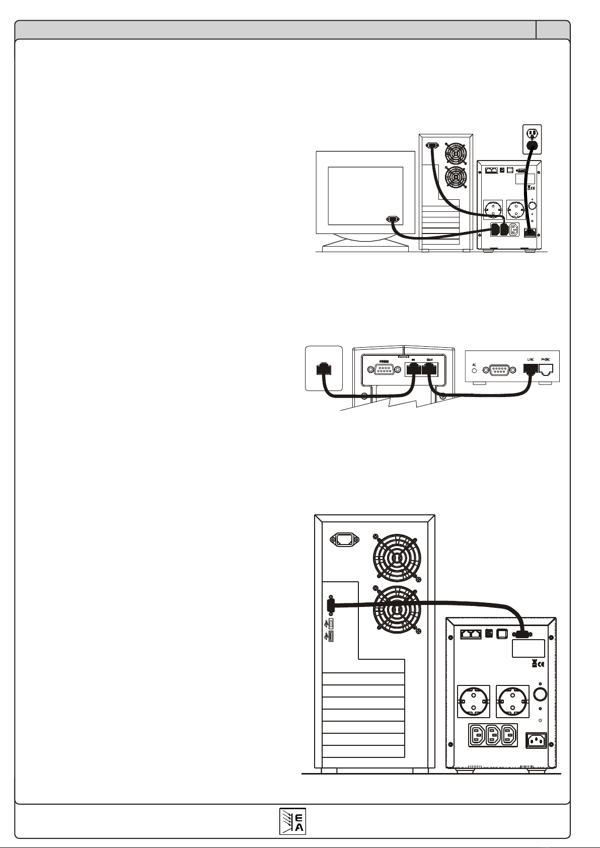
2.3 Anschließen
Schließen Sie zuerst das Gerät an eine ausreichend
gesicherte Steckdose an und dann die Last(en) an
die USV.
Die USV bietet weiterhin einen Überspannungsschutz
für Modem/LAN-Leitungen. Verbinden Sie die zu schüt-
zende Leitung mit den Buchsen auf der Rückseite:
Für eine Überwachung der USV am PC verbinden Sie
noch das mitgelieferte Kommunikationskabel (RS232
oder USB). Sollte das RS232-Kabel zu kurz sein, kann
es mit einem 1:1 Verlängerungskabel verlängert wer-
den. Es wird aber empfohlen, eine Gesamtlänge von
10m nicht zu überschreiten.

5
Betriebsanleitung
Informer Compact USV Serie
DE
Stand 16.10.2014
2.4 Inbetriebnahme
Nachdem alle Verbindungen installiert worden, schalten
Sie die USV durch Drücken der Taste für >4s ein.
Die Anzeige leuchtet auf, die grüne LED sollte ange-
hen und es wird die Belastung in Prozent angezeigt,
sowie die Betriebsart durch das Flußdiagramm. Sollte
das Erdungsfehlerzeichen blinken, ziehen Sie den
Netzstecker (an der Steckdose) und stecken ihn 180°
gedreht wieder ein, sofern möglich.
Das Gerät ist nun betriebsbereit.
Über das Gerät
3. Bedienelemente (Vorderseite)
1 - LED/Symbol „Netzbetrieb“
Netzbetrieb ist der Normalbetrieb der USV bei vorhan-
dener Netzspannung. Die Ausgangsspannung wird
über einen Transformator ausgeregelt und konstant
gehalten.
2 - LED/Symbol „Fehler“
Zeigt Fehler wie Überlast, Kurzschluß am Ausgang
oder andere Fehler an. Zusätzlich ertönt ein Alarm.
3 - Taste EIN / SILENCE
Dient zum Einschalten des Gerätes (>4s drücken) bzw.
zum Stummschalten eines Alarmsignals (>2s drücken),
bis erneut ein Fehler auftritt.
4 - Taste OFF
Dient zum Ausschalten des Gerätes (>4s drücken).
5 - Symbol „Batteriezustand mangelhaft“
Zeigt einen möglicherweise mangelhaften Zustand der
Batterien auf. Diese sollten dann überprüft und ggf.
getauscht werden.
6 - LED/Symbol „Batteriebetrieb“
Zeigt durch permanentes Leuchten den Batteriebetrieb
an, in den die USV wechselt, wenn die Netzspannung
wegfällt bzw. um mehr als 25% absinken sollte.
Sollte die LED im ausgeschalteten Zustand der USV
blinken, zeigt dies an, daß die Batterien geladen wer-
den.
7 - Schraube für Batteriedeckel
8 - Symbol „Batterieladezustand“
Zeigt niedrigen Batterieladezustand an und warnt vorn
drohender Abschaltung der USV.
9 - Flußdiagram
Zeigt symbolisch den Stromuß im Gerät an und da-
durch auch die Betriebsarten.
10 - Symbol „Netzspannung niedrig“
Zeigt an, wenn die Netzspannung um -9% oder mehr
sinken sollte und die USV dies mit +15% ausgleicht
(Boost-Funktion).
11 - Symbol „Netzspannung zu hoch“
Zeigt an, wenn die Netzspannung um 9% oder mehr zu
hoch sein sollte und die USV dies mit -15% ausgleicht
(Buck-Funktion).
IN OUT USB RS232 IN OUT USB RS232
17 18 19 20 21
23
22
24
25
17 18 19 20 21
23
22
24
25
8 1 9 10 11 12 13 146 5 2 15
3 164 6 2 1
DIP Switch Setting
321
VOLTAGE=220V
VOLTAGE=230V
VOLTAGE=240V
VOLTAGE=50Hz
VOLTAGE=60Hz
FUNCTION
7
3 100 06
3 100 20
3 100 07
3 100 08
1. Led für Stromnetzanschluss
2. Alarmleuchte (Led)
3. Taste ON
4. Taste OFF
5. Batterie auswechseln
6. Led Batteriebetrieb
7. Schraube für Batteriedeckel
8. Anzeige für erschöpfte Batterien
9. Bypass-Anzeige
10. Anzeige Stromnetzspannung zu schwach
11. Anzeige Stromnetzspannung zu stark
12. Anzeige USV-Ausgang vorhanden
13. Anzeige falsche Erdung
14. Überlastanzeige
15. Anzeige Prozent der Batterieladung
16. Wahltaste Anzeige der Batterieladung
17. Port RJ45
18. Dip-Schalter
19. Steckerbuchse für Schnittstelle USB
20. Steckerbuchse für Serienschnittstelle RS232
21. Interne CPU-Reset-Taste
22. Ausgangsschalter
23. Ausgänge
24. Eingangs-Schmelzsicherung
25. Steckerbuchse Netzeingang
AChTUNg
Die USV kann nicht im Normalbetrieb eingeschaltet werden,
wenn beide Dip-Schalter DIP-2 und DIP-3 auf ON geschaltet sind.

6
DE
Betriebsanleitung
Informer Compact USV Serie
Stand 16.10.2014
Über das Gerät
1 - Modem/LAN-Schutz
Diese Buchsen bieten einen einfachen Überspan-
nungsschutz einer Modem- oder LAN-Verbindung. Die
Signale werden durchgeschliffen.
2 - Schalter Spannungswahl
Vorsicht! Bei Veränderung der Standardeinstellung
(230V/50Hz) können Schäden am angeschlossenen
Verbraucher entstehen. Mit Vorsicht zu benutzen!
Die Ausgangsspannung kann mit den DIP-Schaltern 2
und 3 verändert werden, was sich allerdings nur auf den
Batteriebetrieb auswirkt. Ansonsten gibt die USV ihre
Nennspannung aus. Der Schalter für die Frequenz dient
zur Wahl des Betriebes mit 50Hz oder 60Hz Frequenz
am Ausgang, für Batteriebetrieb. Während Netzbetrieb
folgt die Ausgangsfrequenz der Netzfrequenz am Ein-
gang. Vorsicht! Die Wahl der falschen Frequenz
kann angeschlossene Lasten beschädigen!
3 - Kommunikationsschnittstellen
Verbinden Sie hier das mitgelieferte Kommunikations-
kabel mit dem PC.
4 - Ausgangsbuchsen
Hier Lasten anschließen.
5 - Eingangssicherung
Falls defekt, nur durch gleichen Typ und Wert ersetzen!
6 - Netzeingangsbuchse
5. Gebrauch
5.1 Allgemeines
Bei Ihrem Gerät handelt es sich um eine unterbre-
chungsfreie Stromversorgung (USV), die nach dem
Line-Interactive-Prinzip arbeitet. Im Normalbetrieb,
also wenn Netzspannung vorhanden ist, wird der Ver-
braucher über die USV mit einer geregelten Spannung
versorgt. Dabei werden durch einen sog. Boost&Buck
Verfahren eventuelle Netzspannungsschwankungen
bis zu einem gewissen Grad ausgeglichen.
5.2 Normalbetrieb
Normalbetrieb ist Netzbetrieb. Das heißt, es ist Netz-
spannung vorhanden und die USV versorgt den Ver-
braucher über einen Trafo. Dies wird durch die LED
„Netzbetrieb“ angezeigt. Ausgangsspannung ist an den
Lastanschlußbuchsen nur vorhanden, wenn die USV
eingeschaltet ist.
12 - Symbol LOAD
Zeigt an, daß Ausgangsspannung vorhanden ist.
13 - Symbol „Erdefehler“
Zeigt an, wenn ein Erdungsfehler der Netzzuleitung
besteht (PE-Leitung fehlend/defekt) oder wenn die
Netzsynchronisation nicht richtig arbeitet.
14 - Symbol „Überlast“
Zeigt Belastung von >100% an. Bei dauerhafter Über-
last schaltet das Gerät nach einiger Zeit aus. Diese
hängt von der Höhe der Überlast ab. Abschaltung
erfolgt nach 20s Überlast von >110% und nach 2s
Überlast von >125%.
15 - Anzeige Lastlevel / Batterieladezustand
Zeigt die Belastung der USV durch den Verbraucher
bzw. den Batterieladezustand an. Wechseln der An-
zeige erfolgt mit der Taste . Während der Lastlevel
angezeigt wird, ist ein Symbol ▲ im Flußdiagramm
unter LOAD, bei Batterieladezustandsanzeige ist das
Symbol zu sehen. Bei niedrigem Ladezustand wird
angezeigt.
16 - Taste Batterie/Last
Dient zum Umschalten der Anzeige von Lastlevel zu
Batterieladezustand und umgekehrt.
4. Anschlüsse (Rückseite)
IN OUT USB RS232
1 2 3 3
5
6
4

7
Betriebsanleitung
Informer Compact USV Serie
DE
Stand 16.10.2014
Über das Gerät
5.3 Batteriebetrieb
Die USV wechselt automatisch in den Batteriebetrieb,
wenn:
- die Netzspannung wegfällt (Stromausfall).
- die Netzspannung außerhalb des zulässigen Berei-
ches (±25%) gelangen sollte.
Dies wird durch einen Alarmton und die LED bzw. das
Symbol „Batteriebetrieb“ angezeigt. Der Alarm ertönt,
solange der Batteriebetrieb läuft. Der Verbraucher
wird über einen Wandler von den Batterien versorgt,
die sich dadurch kontinuierlich entladen und die Über-
brückungszeit aufbrauchen. Sind diese bis zu einem
gewissen Stand entladen, droht Tiefentladung. Um
dies zu vermeiden, warnt die USV rechtzeitig mit ei-
nem Alarmton und der Anzeige des Symbol „Batterie
niedrig“ ( ). Danach wird sich die USV nach kurzer
Zeit selbst abschalten und die Verbraucher mit, was
sofortigen Datenverlust zur Folge haben kann. Eine
Überwachung der USV kann durch eine kostenlos als
Download verfügbar Software erfolgen, die ggf. den
Rechner automatisch herunterfährt. Die Kommunika-
tionsverbindung erfordert ein Datenkabel, das in der
Lieferung enthalten ist.
5.4 Kaltstart
Die USV kann auch ohne vorhandenes Netz gestartet
werden. Es genügt, sie ganz normal einzuschalten. Der
Verbraucher wird dann über die Batterien versorgt. Bei
Netzwiederkehr wechselt die USV automatisch in den
Normalbetrieb.
5.5 Wartung
Die USV erfordert selbst keine Wartung. Lediglich die
Batterien müssen nach Ende ihrer Lebensdauer ge-
tauscht werden. Der Zustand der Batterien wird von
der USV überwacht. Sollten die Batterien nicht in Ord-
nung sein, so wird dies mit dem Symbol angezeigt.
Dann ist ein Austausch einzelner oder aller Batterien
erforderlich.
Für die umweltgerechte Entsorgung der Batterien ist
der Anwender selbst zuständig!
5.6 Fehlersituationen
Überlast, Überhitzung sowie Überspannung bzw. Un-
terspannung am Netzeingang sind Fehlersituationen,
denen die USV unterschiedlich begegnet. Um Schäden
am Gerät zu vermeiden, wird sich die USV bei Über-
schreiten kritischer Grenzen abschalten und die unter-
brechungsfreie Stromversorgung des Verbrauchers ist
nicht mehr gewährleistet. Folgendes gilt:
Überhitzung -> Alarm, dann Abschaltung
Überlast -> Alarm, dann Abschaltung
Unterspannung -> Alarm und Batteriebetrieb
Überspannung -> Alarm, dann Abschaltung
5.7 Fernüberwachung
Über die eingebauten Schnittstellen RS232 oder
USB kann die USV von einem PC und einer Software
fernüberwacht werden. Die Software kann Anwender
Netzausfall rechtzeitig warnen und ggf. den PC auto-
matisch herunterfahren, um einen plötzlichen Ausfall
zu verhindern. Die kostenlos USV-Software „UPS
Communicator“ ist für Windows und Linux erhältlich und
kann von www.elektroautomatik.de heruntergeladen
werden bzw. ist auf Anfrage erhältlich.
6. Technische Daten
INFC1000 INFC2000 INFC3000
6.1 Eingang
Scheinleistung 1000VA 2000VA 3000VA
Wirkleistung 600W 1200W 1800W
Spannung 230VAC nominal,
Bereich 160...290V
Frequenz 50/60Hz ±5%
6.2 Ausgang
Spannung Netzbetr. 230VAC ±10%
Spannung Batt.betr. 230VAC ±10%
Spannungsform echter Sinus, THD <3%
Frequenz Netzbetrieb: wie Eingang
Batteriebetrieb: 50Hz o. 60Hz
Umschaltzeit max. 6ms
6.3 Batterien
Anzahl 2 4 4
Typ 12V 7,2Ah
Batteriespannung 24VDC 48VDC
Überbrückungszeit
bei 80% Last 5min. 5min. 5min.
Aufladezeit 4h (auf ~90%)
6.4 Andere
Gewicht 13kg 22kg 24kg
Größe
Breite 169mm
Höhe 242mm
Tiefe 361mm 464mm
Geräuschentw. <40dBA@1m
7. Lagerung
Bei längerer Lagerung des Gerätes sollten die Bat-
terien alle 6 Monate geladen werden, falls es bei
-15°C...+30°C gelagert wird, bzw. alle 3 Monate, falls
es bei -15°C...+45°C gelagert wird.


9
EN
Date: 10-16-2014
Operating Guide
Informer Compact UPS Series
About & Copyright
Elektro-Automatik GmbH & Co. KG
Helmholtzstrasse 31-33
41747 Viersen
Germany
Phone: +49 (0) 2162 / 37850
Fax: +49 (0)2162 / 16230
Web: www.elektroautomatik.de
Mail: [email protected]
© Elektro-Automatik
Reprint, duplication or partly, wrong use of this user
instruction manual are prohibited and might be followed
by legal consequences.
Important notes:
• To ensure safety in all applications where an UPS is
hard- wired to the mains supply, ensure that the system is
installed by authorised staff.
• Those UPS systems supplied with a factory input lead can
be safely connected to the wall socket by the purchaser.
• The UPS has its own internal energy source (battery).
Should the UPS be switched on when no AC power is
available, there could be voltage at the output terminals.
• Make sure that the mains supply socket is correctly ground-
ed.
• Do not open the case as there are no serviceable parts
inside. Do not try to repair the unit yourself, contact your
local supplier or your warranty will be void.
• Please make sure that the input voltage of the UPS match-
es the mains supply voltage.
• Use a certied input power cable with the correct plugs
and sockets for the appropriate voltage system.
• To prevent any overheating of the UPS, keep all ventilation
openings free from obstruction and do not store things on
top of the UPS. Keep the UPS 20cm away from the wall.
• Make sure the UPS is installed within an environment as
specied (0-40°C and 0-95% non-condensing humidity).
• Do not install the UPS in direct sunlight. Your warranty may
be void if the batteries fail.
• Install the UPS indoors as it is not designed for outdoor
installation.
• Dusty, corrosive and salty environments can do damage
to UPS.
• Install the UPS away from objects which produce extreme
heat and areas that are extremely wet.
• The battery will discharge naturally if the system is not
used for a longer time so the UPS should be recharged
every 2-3 months, if not used. If this is not done, then
the warranty will be void. When installed and being used,
the batteries will be automatically recharged and kept in
top condition.
This UPS has been designed and constructed to protect
your assets from the wide range of uctuations and distor-
tions experienced on power lines today. It is your insurance
for reliable, clean and stable voltage supply and it is worth
taking care to install the system correctly and to have it
maintained regularly by your local distributor.
Warning!
• It is intended for installation in a controlled environment.
• Servicing of batteries should be performed or supervised
by personnel instructed about batteries and the required
precautions. Keep unauthorised personnel away from
batteries.
• Caution! Do not dispose batteries into re. They might
explode.
• Caution! Do not open or mutilate the battery or batteries.
Released electrolyte is harmful to the skin and eyes. It
might be toxic.
• Caution! Risk of electric shock – the battery circuit is not
isolated from AC. Hazardous voltage might exist between
battery terminals and ground.
10
EN
Operating Guide
Informer Compact UPS Series
Date: 10-16-2014
1. Introduction
Thank you for selecting this Uninterruptible Power
Supply (UPS). It provides you with a perfect protection
for connected equipment. The manual is a guide to
install and use the UPS. It includes important safety
instructions for operation and correct installation of the
UPS. If you have any problems with the UPS, please
refer to this manual before calling a technical service.
The device works according to the Line Interactive
principle and offers an AVR feature, which means an
automatic voltage regulation of the output voltage by
using a boost & buck circuit. It can compensate mains
voltage uctuations in a range of 70%...125% nominal
mains voltage.
For data safety and timely shutdown of PCs, the UPS
features two communication ports for monitoring pur-
poses.
2. Installation
2.1 Unpacking
1. The UPS device weighs between 13kg and 24kg,
depending on the model. Be careful when unpacking
and lifting it. Improper use of force might harm you.
2. Included in the delivery are:
- 1x User manual German/English
- 1x UPS communication cable RS232
- 1x UPS communication cable USB
- 1x Modem cable
- 1x Mains cord, type IEC
2.2 2.2 Selecting installation position
It is necessary to select a proper environment to install
the unit, in order to minimize the possibility of damage
to the UPS and extend its life time. Please follow the
advices below:
1. Keep at least 20cm (8 inches) clearance from the
rear panel of the UPS to the wall.
2. Do not block the airow to the ventilation openings
of the unit.
3. Please check the installation environment to avoid
overheat and excessive moisture.
4. Do not place the UPS in an environment near dusty,
corruptive or salty material or ammable objects.
5. Do not expose the UPS to outdoors.
About the device
2.3 Load connection
First connect the UPS to a mains supply socket that
is fused according to the requirements. Then connect
the load(s) to the UPS.
The device also features a surge protection for modem/
LAN connections. Connect the communication line to
protect with the two sockets on the rear. The signals
are led through:
In order to supervise the UPS with a PC, connect one
of the included communication cables. In case the
included RS232 cable is too short, it can be extended
by a 1:1 extension cable. But it is recommended to not
exceed 10m total length.

11
EN
Date: 10-16-2014
Operating Guide
Informer Compact UPS Series
About the device
3. Front panel elements
1 - LED/Symbol „Mains OK“
Mains operation is the normal operation of the UPS, if
mains voltage is present. The output voltage is provided
to the output via a transformer and is held constant.
2 - LED/Symbol „Error“
Indicates errors like overload, short-circuit at the output
or other errors. Is accompanied by an audible alarm.
3 - Button ON / SILENCE
This button is used to switch the UPS on by pressing it
>4s, as well as to mute the audible alarm (press >2s)
until a new error occurs.
4 - Button OFF
Is used to switch the UPS off (press >4s).
5 - Symbol „Battery replacement“
Indicates an insufcient capacity and a probably bad
condition of the batteries. Once this is indicated, they
should be maintained, i.e. replaced.
6 - LED/Symbol „Battery operation“
Indicates that the battery operation is active, because of
mains loss or because the mains voltage has dropped
by more than 25%.
In case the LED is ashing, while the UPS is switched
off, this indicates that the batteries are charged.
7 - Screw for battery cover
8 - Symbol „Low battery“
Indicates a low battery level and warns against immi-
nent shutdown of the UPS.
9 - Flow chart
Shows symbolically the current ow inside the UPS
and thereby the operation modes.
10 - Symbol „Mains low“
Indicates that the mains voltage has dropped down by
-9% or more. The UPS compensates this with +15%
voltage increase (boost).
11 - Symbol „Mains high“
Indicates, that the mains voltage is too high (9% or
more). The UPS will then compensate this by -15%
(buck).
12- Symbol LOAD
Indicates voltage is present at the output.
2.4 First time operation
After all necessary connections have been made,
switch the UPS on by pressing the button for >4s.
The display will light up and the green LED should
indicate mains supply is present. The display shows
the load level in %, as well as the operation mode in
the little ow chart. In case the symbol is blinking,
pull the mains cord (at the mains socket) and plug it in
again, rotated by 180°.
The device is now ready to work.
IN OUT USB RS232 IN OUT USB RS232
17 18 19 20 21
23
22
24
25
17 18 19 20 21
23
22
24
25
8 1 9 10 11 12 13 146 5 2 15
3 164 6 2 1
DIP Switch Setting
321
VOLTAGE=220V
VOLTAGE=230V
VOLTAGE=240V
VOLTAGE=50Hz
VOLTAGE=60Hz
FUNCTION
7
3 100 06
3 100 20
3 100 07
3 100 08
1. Led für Stromnetzanschluss
2. Alarmleuchte (Led)
3. Taste ON
4. Taste OFF
5. Batterie auswechseln
6. Led Batteriebetrieb
7. Schraube für Batteriedeckel
8. Anzeige für erschöpfte Batterien
9. Bypass-Anzeige
10. Anzeige Stromnetzspannung zu schwach
11. Anzeige Stromnetzspannung zu stark
12. Anzeige USV-Ausgang vorhanden
13. Anzeige falsche Erdung
14. Überlastanzeige
15. Anzeige Prozent der Batterieladung
16. Wahltaste Anzeige der Batterieladung
17. Port RJ45
18. Dip-Schalter
19. Steckerbuchse für Schnittstelle USB
20. Steckerbuchse für Serienschnittstelle RS232
21. Interne CPU-Reset-Taste
22. Ausgangsschalter
23. Ausgänge
24. Eingangs-Schmelzsicherung
25. Steckerbuchse Netzeingang
AChTUNg
Die USV kann nicht im Normalbetrieb eingeschaltet werden,
wenn beide Dip-Schalter DIP-2 und DIP-3 auf ON geschaltet sind.

12
EN
Operating Guide
Informer Compact UPS Series
Date: 10-16-2014
2 - DIP switch „Voltage selection“
Caution! Changing the default setting (230V/50Hz)
can cause damage to your load. Use at your own risk!
The output voltage can be selected with DIP switches
2 and 3, but only for battery operation. So it is not rec-
ommended to change these. The frequency setting is
used to select the mains frequency the UPS is dedi-
cated to run with in battery operation mode. In normal
mode, the output frequency follows the input frequency.
If the wrong setting is used, the UPS will always start
in battery mode. Careful! Accidentally setting the
frequency to 60Hz can damage connected 50Hz
loads (or vice versa)!
3 - Communication interfaces
Connects the UPS with a PC via the included commu-
nication cable.
4 - Output sockets
Connect your loads here.
5 - Input fuse
If blown, only replace with same type and value!
6 - Mains input socket
5. Operation
5.1 General
This device is an uninterruptible power supply (UPS)
which is working according to the Line Interactive
principle. It means that in normal operation, if mains
voltage is present, the load is supplied by the UPS with
a stabilised voltage, using a so-called boost & buck
circuit which can compensate occurring mains voltage
uctuations up to a certain level.
5.2 Normal operation
Normal operation is mains operation. It means that,
as long as mains voltage is present, the output volt-
age is supplied from the mains via a transformer. This
operation is indicated by the „Mains OK“ LED. Output
voltage is only available at the output sockets if the
UPS is switched on.
About the device
13 - Symbol „Polarity/Grounding error“
Indicates a grounding error (PE conductor missing
or broken) or wrong phase potential of the AC supply
against PE.
14 - Symbol „Overload“
Indicates a load of >100%. At continuous overload the
unit will switch off after a certain time. This time depends
on the level of overload. It will shut down after 20s if
overload is >110% and after 2s if it is >125%.
15 - Indication of load level / battery level
Indicates the load level or battery level. Value can be
changed with the button . If the load level is shown,
the symbol ▲ is displayed in the ow chart under LOAD.
If battery level is shown, the symbol is displayed,
while it shows at low battery level.
16 - Button Battery / Load
Is used to toggle between indication of load level and
battery level.
4. Terminals (rear side)
IN OUT USB RS232
1 2 3 3
5
6
4
1 - Modem/LAN protection
These sockets offer a simple surge protection for mo-
dem or LAN connections. The signals are led through.

13
EN
Date: 10-16-2014
Operating Guide
Informer Compact UPS Series
About the device
5.3 Battery operation
The UPS changes automatically to battery operation, if:
- mains loss occurs (blackout).
- the mains voltage is out of range (±25%).
The switchover is indicated by the LED „Battery opera-
tion“ and an audible alarm. This alarm is active as long
as the battery operation is running, unless silenced.
The load is then supplied from the batteries and via an
internal inverter. It constantly discharges the batteries. If
a certain level is reached, deep discharge is imminent.
In order to avoid this, the UPS warns the user by an
audible alarm and the symbol is displayed in the
LCD panel. After this, only a short period remains until
the UPS switches itself off and thus any connected
load. This can lead to data loss. The supervision of the
UPS by a management software, which is available as
download free of charge, can avoid data loss.
5.4 5.4 Cold start
The UPS can be also be started without mains voltage
present, by starting it as usual. The load is then supplied
from the batteries. As soon as mains returns, the UPS
will automatically switch to normal operation.
5.5 Maintenance
The UPS does not require maintenance. Only the bat-
teries have to be replaced at the end of their lifespan,
which varies according to many circumstances. The
state of the batteries is supervised by the UPS battery
management circuit. In case the batteries are faulty, it
is indicated in the display with the symbol. A replace-
ment of the batteries may be required then.
The user has to take care for the environmentally
friendly disposal of the batteries!
5.6 Error situations
Overload, overheating as well as overvoltage resp.
undervoltage at line input are situations to which the
UPS is reacting in different ways. In order to prevent
damage, the unit will switch off if limits are exceeded.
In this case the loads are also immediately shut off!
Following applies:
Overheating -> Alarm, then shutdown
Overload -> Alarm, then shutdown
Undervoltage -> Alarm and battery operation
Overvoltage -> Alarm, then shutdown
5.7 Remote monitoring
The integrated RS232 and USB interfaces can be used
to monitor the UPS by a standard PC and a software. in
case of a power fail, it can warn the user in time or shut
down the PC and other equipment supplied by the UPS
automatically, or even send a broadcast message to
other PCs in a network to initiate shutdown. The free-of-
charge software „UPS Communicator“ is available for
Windows or Linux and can be downloaded from www.
elektroautomatik.de or can be obtained upon request.
6. Technical specs
INFC1000 INFC2000 INFC3000
6.1 Input
Apparent power 1000VA 2000VA 3000VA
Real power 600W 1200W 1800W
Voltage 230VAC nominal,
range 160...290V
Frequency 50/60Hz ±5%
6.2 Output
Voltage @ mains 230VAC ±10%
Voltage @ battery 230VAC ±10%
Voltage wave form true sine wave, THD <3%
Frequency same as input
Transfer time max. 6ms
6.3 Batteries
Number 2 4 4
Type 12V 7Ah
Voltage 24VDC 48VDC
Backup time at 80%
load 5min. 5min. 5min.
Recharge time 4h (to ~90%)
6.4 Other
Weight 13kg 22kg 24kg
Dimensions Tower
Width 169mm
Heigh 242mm
Depth 361mm 464mm
Audible noise <40dBA@1m
7. Storage
Keeping the UPS in storage for a longer time requires
the batteries to be fully charged every 6 months if
kept at -15°C...+30°C ambient temperature or every 3
months at -15°C...+45°C.


EA-Elektro-Automatik GmbH & Co. KG
Entwicklung - Produktion - Vertrieb
Helmholtzstraße 31-33
41747 Viersen
Telefon: 02162 / 37 85-0
Telefax: 02162 / 16 230
www.elektroautomatik.de
This manual suits for next models
2
Table of contents
Languages:
Other Elektro-Automatik UPS manuals

Elektro-Automatik
Elektro-Automatik Guard LCD 2 Series User manual

Elektro-Automatik
Elektro-Automatik PSB Rack 15U User manual

Elektro-Automatik
Elektro-Automatik PSI Rack 24U User manual

Elektro-Automatik
Elektro-Automatik PSB Rack 15U User manual

Elektro-Automatik
Elektro-Automatik Guard LCD 2 Series Operator's manual


