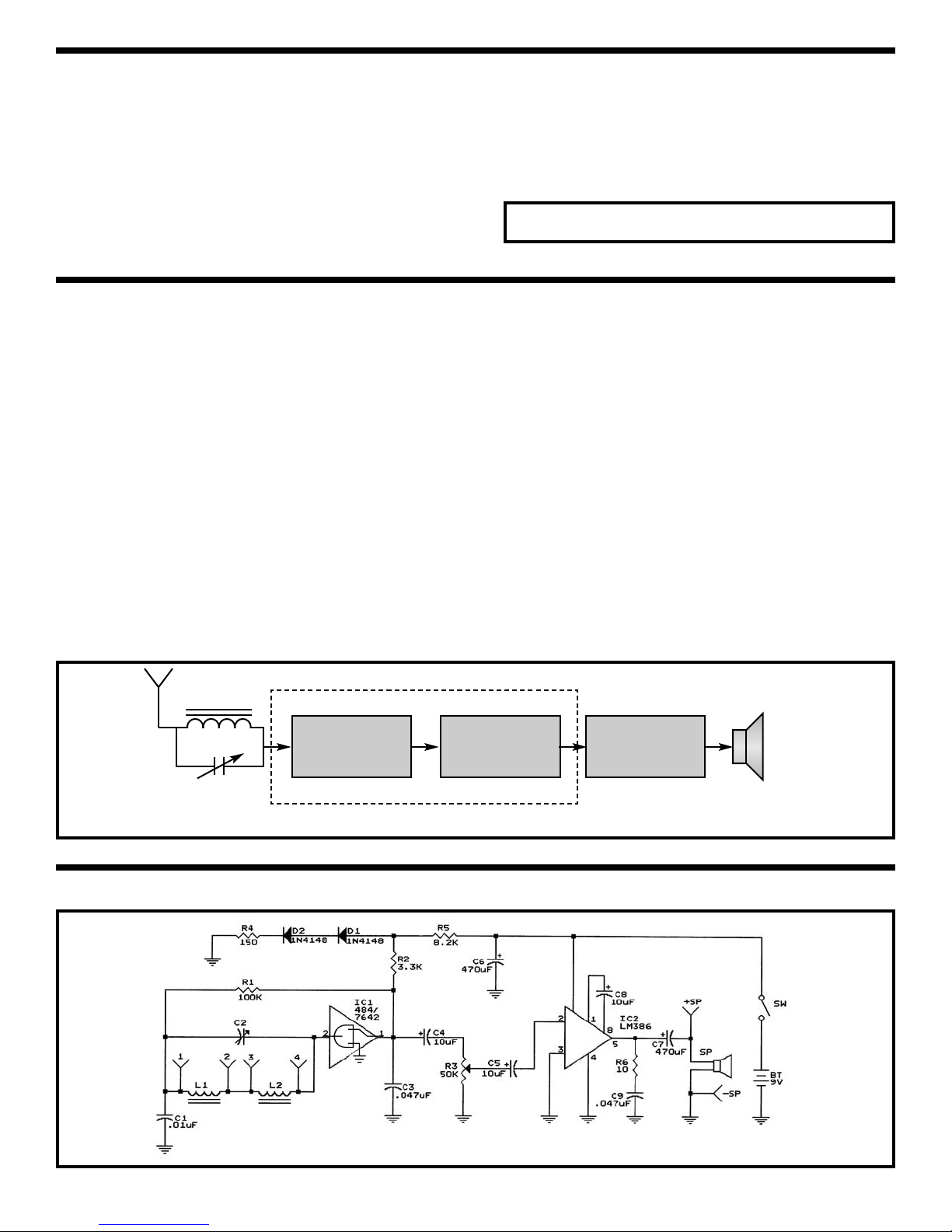
Elenco Electronics AM-780K User guide

AM RADIO KIT
MODEL AM-780K
Assembly and Instruction Manual
Elenco®Electronics, Inc.
Copyright © 2007, 1999 by Elenco®Electronics, Inc. All rights reserved. Revised 2007 REV-F 753108
No part of this book shall be reproduced by any means; electronic, photocopying, or otherwise without written permission from the publisher.

PARTS LIST
If you are a student, and any parts are missing or damaged, please see instructor or bookstore.
If you purchased this kit from a distributor, catalog, etc., please contact Elenco®Electronics (address/phone/e-
mail is at the back of this manual) for additional assistance, if needed. DO NOT contact your place of purchase
as they will not be able to help you.
RESISTORS
Qty. Symbol Value Color Code Part #
1 R6 10Ω5% 1/4W brown-black-black-gold 121000
1 R4 150Ω5% 1/4W brown-green-brown-gold 131500
1R2 3.3kΩ5% 1/4W orange-orange-red-gold 143300
1R5 8.2kΩ5% 1/4W gray-red-red-gold 148200
1 R1 100kΩ5% 1/4W brown-black-yellow-gold 161000
1 R3 Potentiometer 50kΩ& 192522
switch w/ Nut & Washer
CAPACITORS
Qty. Symbol Value Description Part #
1 C2 Variable Tuning Capacitor 211677
1C1 .01μF Discap (103) 241031
2 C3, C9 .047μF Discap (473) 244700
3 C4, C5, C8 10μF Electrolytic Radial 271045
2 C6, C7 470μF Electrolytic Radial 284743
SEMICONDUCTORS
Qty. Symbol Value Description Part #
2 D1, D2 1N4148 Semiconductor Silicon Diode 314148
1 IC2 LM-386 Integrated Circuit 330386
1 IC1 484 / 7642 Integrated Circuit 33K484
MISCELLANEOUS
PARTS IDENTIFICATION
Qty. Description Part #
1 Antenna with Holders 484004
1 PC Board 517053
1 Battery Holder 590096
1 Speaker 8Ω590102
1 Knob for Potentiometer 622017
1 Knob for Variable Capacitor 622030
1 Screw 2-56 x 5/16” 641231
Qty. Description Part #
3 Screw #3 x 5/32” 641310
1 Nut 2-56 644201
1 Socket IC 8-pin 664008
1 Label 720421
1 Speaker Pad 780128
4 Wire 2” 834011
1 Solder Lead-free 9LF99
-1-
RESISTORS SEMICONDUCTORS
Resistor Diode
484 / 7642
LM-386
IC Socket
Antenna with Holders
MISCELLANEOUS
Speaker
50kΩPotentiometer
and Switch
CAPACITORS
Discap Electrolytic
Radial
Tuning
Battery Holder
Knob (dial)
Knob
(pot)
Label
Screw
#3 x 5/32”
Nut
2-56
Screw
2-56 x 5/16”
Speaker Pad

-2-
• 9V Battery
• 25 or 30 watt Soldering Iron
• Small Phillips and Slotted Screwdrivers
• Long Nose Plier
• Side Cutters
IDENTIFYING RESISTOR VALUES
Use the following information as a guide in properly identifying the value of resistors.
BANDS
METRIC UNITS AND CONVERSIONS
Abbreviation Means Multiply Unit By Or
p Pico .000000000001 10-12
n nano .000000001 10-9
μmicro .000001 10-6
m milli .001 10-3
– unit 1 100
k kilo 1,000 103
M mega 1,000,000 106
1. 1,000 pico units = 1 nano unit
2. 1,000 nano units = 1 micro unit
3. 1,000 micro units = 1 milli unit
4. 1,000 milli units = 1 unit
5. 1,000 units = 1 kilo unit
6. 1,000 kilo units = 1 mega unit
You Will Need:
IDENTIFYING CAPACITOR VALUES
Capacitors will be identified by their capacitance value in pF (picofarads), nF (nanofarads), or μF (microfarads).
Most capacitors will have their actual value printed on them. Some capacitors may have their value printed in
the following manner. The maximum operating voltage may also be printed on the capacitor.
Second Digit
First Digit
Multiplier
Tolerance*
Note: The letter “R”
may be used at times
to signify a decimal
point; as in 3R3 = 3.3
103K
100V
The letter M indicates a tolerance of +20%
The letter K indicates a tolerance of +10%
The letter J indicates a tolerance of +5%
Maximum Working Voltage
The value is 10 x 1,000 =
10,000pF or .01μF 100V
*
Electrolytic capacitors have a positive
and a negative electrode. The
negative lead is indicated on the
packaging by a stripe with minus
signs and possibly arrowheads.
Warning:
If the capacitor is
connected with
incorrect polarity, it
may heat up and
either leak, or cause
the capacitor to
explode.
Polarity
Marking
BAND 1
1st Digit
Color Digit
Black 0
Brown 1
Red 2
Orange 3
Yellow 4
Green 5
Blue 6
Violet 7
Gray 8
White 9
BAND 2
2nd Digit
Color Digit
Black 0
Brown 1
Red 2
Orange 3
Yellow 4
Green 5
Blue 6
Violet 7
Gray 8
White 9
Multiplier
Color Multiplier
Black 1
Brown 10
Red 100
Orange 1,000
Yellow 10,000
Green 100,000
Blue 1,000,000
Silver 0.01
Gold 0.1
Resistance
Tolerance
Color Tolerance
Silver ±10%
Gold ±5%
Brown ±1%
Red ±2%
Orange ±3%
Green ±0.5%
Blue ±0.25%
Violet ±0.1%
12 Multiplier Tolerance
Multiplier For the No. 0 1 2 3 4 5 8 9
Multiply By 110 100 1k 10k 100k .01 0.1

INTRODUCTION
-3-
Radio
Frequency
Amplifier
Detector Audio
Amplifier
Figure 1
IC 484 / 7642 IC LM-386 Speaker
The Model AM-780K AM Radio can be best
understood by analysis of the block diagram shown
in Figure 1.
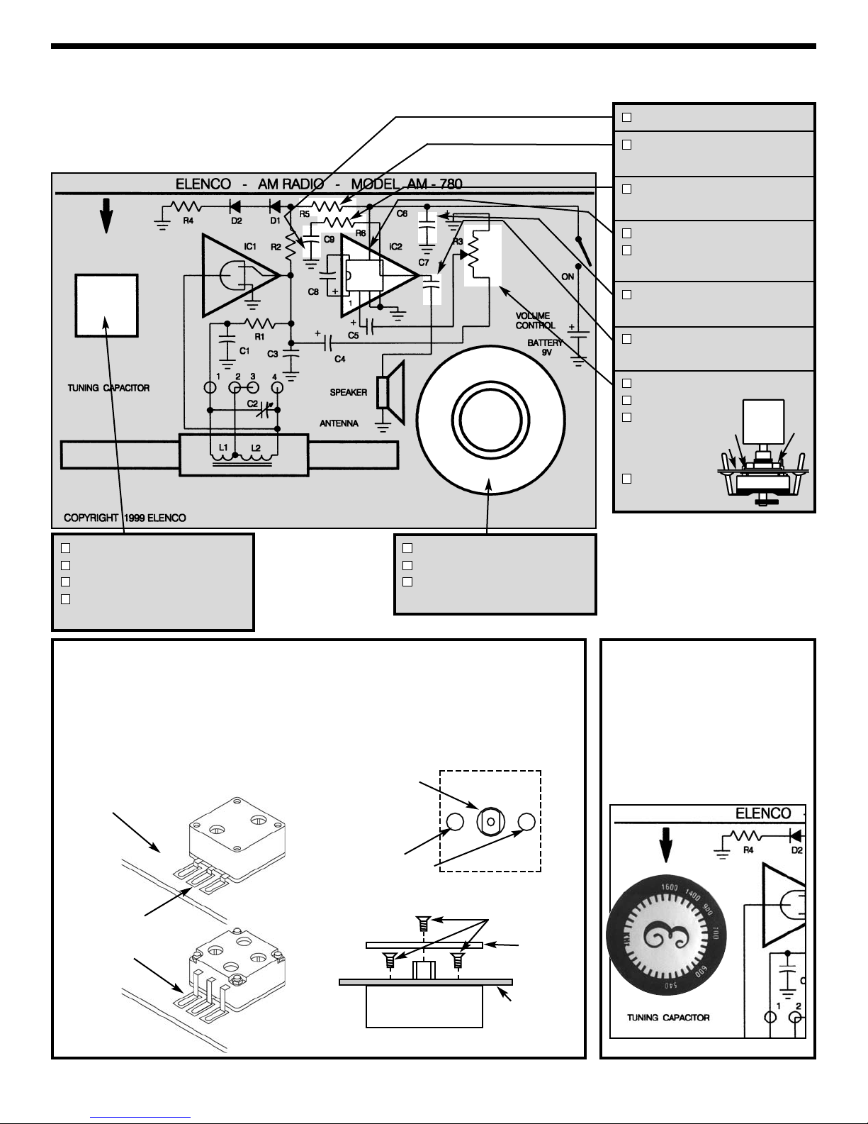
The coils on the ferrite rod antenna (L1 and L2) and
the variable capacitors (C2) make up a “tuned circuit”
(see schematic diagram below). It is a very selective
filter. The frequency is selectable over a certain range
by adjusting the tuning capacitor. The selectable
signal is passed into IC1 (integrated circuit 484/7642)
where it is amplified and then detected. The 484/7642
is a monolithic integral circuit equal to a ten transistor
tuned radio frequency circuit. The resistor R2 and the
capacitor C3 set the automatic gain control of IC1.
The 484/7642 requires a low voltage power supply
(1.1 - 1.8V). The voltage drop across diodes D1, D2,
and resistor R4 is the correct supply voltage to IC1.
The output from a diode detector of the 484/7642 is
typically 40 - 60mV. This audio signal is too weak to
drive a speaker directly. Capacitor C3 filters out the
radio frequency component of the signal, leaving a
clean audio signal.
The amount of gain control is varied by potentiometer
R3, which also varies the audio level and
consequently the volume. Capacitor C5 couples the
audio signal from the volume control to the input of
the audio amplifier. Our kit uses the standard design
for the audio amplifier on the base of the integral
circuit LM-386. To make the LM-386 a more versitile
amplifier, two pins (1 and 8) are provided for gain
control. With pins 1 and 8 open, the gain at 20, the
capacitor will go up to 200. Capacitor C7 blocks the
DC from the speaker while allowing the AC to pass.
SCHEMATIC DIAGRAM AM-780K
The AM-780K is a tuned radio frequency (TRF)
receiver of the standard AM (amplitude modulation)
broadcast frequencies (550kHz - 1600kHz). Easy-
to-build, using only two integral circuits (IC).
Assembly of your AM-780K AM Radio Kit will prove
to be an exciting project and give you much
satisfaction and personal achievement. Care must
be given to identifying the proper components and
in good soldering habits. Above all, take your time
and follow these easy step-by-step instructions.
Remember, “An ounce of prevention is worth a
pound of cure”. Avoid making mistakes and no
problems will occur.
Construction Time: About 3 Hours.
WHAT IT IS

-4-
Introduction
The most important factor in assembling your AM-780K AM Radio Kit is good soldering techniques. Using the
proper soldering iron is of prime importance. A small pencil type soldering iron of 25 - 30 watts is
recommended. The tip of the iron must be kept clean at all times and well tinned.
Safety Procedures
• Wear eye protection when soldering and during all phases of construction.
• Locate soldering iron in an area where you do not have to go around it or reach over it.
•Do not hold solder in your mouth. Wash your hands thoroughly after handling solder.
• Be sure that there is adequate ventilation present.
Assemble Components
In all of the following assembly steps, the components must be installed on the top side of the PC board unless
otherwise indicated. The top legend shows where each component goes. The leads pass through the
corresponding holes in the board and are soldered on the foil side.
Use only rosin core solder.
DO NOT USE ACID CORE SOLDER!
CONSTRUCTION
Solder Soldering Iron
Foil
Solder
Soldering Iron
Foil
Component Lead
Soldering Iron
Circuit Board
Foil
Rosin
Soldering iron positioned
incorrectly.
Solder
Gap
Component Lead
Solder
Soldering Iron
Drag
Foil
1. Solder all components from
the copper foil side only.
Push the soldering iron tip
against both the lead and
the circuit board foil.
2. Apply a small amount of
solder to the iron tip. This
allows the heat to leave the
iron and onto the foil.
Immediately apply solder to
the opposite side of the
connection, away from the
iron. Allow the heated
component and the circuit
foil to melt the solder.
1. Insufficient heat - the
solder will not flow onto the
lead as shown.
3. Allow the solder to flow
around the connection.
Then, remove the solder
and the iron and let the
connection cool. The
solder should have flowed
smoothly and not lump
around the wire lead.
4.
Here is what a good solder
connection looks like.
2. Insufficient solder - let the
solder flow over the
connection until it is
covered. Use just enough
solder to cover the
connection.
3. Excessive solder - could
make connections that you
did not intend to between
adjacent foil areas or
terminals.
4. Solder bridges - occur
when solder runs between
circuit paths and creates a
short circuit. This is usually
caused by using too much
solder. To correct this,
simply drag your soldering
iron across the solder
bridge as shown.
What Good Soldering Looks Like
A good solder connection should be bright, shiny,
smooth, and uniformly flowed over all surfaces.
Types of Poor Soldering Connections
Foil Side
Mount Part Bend Leads to
Hold Part
Solder and
Cut Off Leads

Figure Ca
Mount capacitor C6 on the
back of the PC board in
the location shown. Make
sure the lead with the
polarity marking is in the
correct hole as shown.
Figure C
-5-
ASSEMBLE COMPONENTS TO THE PC BOARD
Place a check mark in the box provided next to each step to indicate that the step is completed.
Figure A
Mount diode with the band in the
same direction as marked on the PC
board. Solder and cut off the excess
leads.
Electrolytics have a
polarity marking
indicating the (–)
lead. The PC board
is marked to show
the lead position.
Warning: If the capacitor is
connected with incorrect polarity,
or if it is subjected to voltage
exceeding its working voltage, it
may heat up and either leak or
cause the capacitor to explode.
Figure D
Insert the IC
socket into the PC
board with the
notch in the
direction shown
on the top legend.
Solder the IC
socket into place.
Insert the IC into
the socket with
the notch in the
same direction as
the notch on the
socket.
Notch
Figure E
D1 - 1N4148 Diode
D2 - 1N4148 Diode
(see Figure A)
R4 - 150Ω5% 1/4W Res.
(brown-green-brown-gold)
R2 - 3.3kΩ5% 1/4W Res.
(orange-orange-red-gold)
IC1 - 484 / 7642 IC
(see Figure B)
R1 - 100kΩ5% 1/4W Res.
(brown-black-yellow-gold)
C1 - .01μF Discap (103)
C3 - .047μF Discap (473)
C5 - 10μF Electrolytic
C4 - 10μF Electrolytic
C8 - 10μF Electrolytic
(see Figure C)
Pad
Backing
Speaker
Backing
Step 1 Step 2 Step 3 Step 4
PC Board
(solder side)
Step 1: If the speaker pad
has center and outside
pieces, then remove them.
Peel the backing off of one
side of the speaker pad and
stick the pad onto the
speaker.
Step 2: Remove the other
backing from the speaker pad.
Step 3: Stick the speaker
onto the solder side of the PC
board.
Step 4: Solder the 2 wires
from the speaker to the pads
+SP and –SP.
Polarity Mark
(–) (+)
Band
Figure B
Mount the IC with
the flat side in the
same direction as
marked on the PC
board. Solder and
cut off the excess
leads.
Flat
Polarity
Mark

C9 - .047μF Discap (473)
R5 - 8.2kΩ5% 1/4W Res.
(gray-red-red-gold)
R6 - 10Ω5% 1/4W Res.
(brown-black-black-gold)
Socket IC 8-pin
IC2 - LM-386 IC
(see Figure D)
C6 - 470μF Electrolytic
(see Figure Ca)
C7 - 470μF Electrolytic
(see Figure C)
R3 - Potentiometer
Nut & Washer
Knob
Solder 5 lugs
to PC board.
-6-
ASSEMBLE COMPONENTS TO THE PC BOARD
Tuning Capacitor
Figure F
Your kit may contain a 3 lead or a 4 lead capacitor. Bend the leads as
shown. Fasten C1 into place on the top side of the PC board with two #3 x
5/32” screws. Fasten the knob to the shaft of the gang with a screw.
Solder leads
to pads
3 Leads
4 Leads
Foil Side
Figure G
Turn the dial fully clockwise.
Remove the protective backing
from the label and align the 1600
with the arrow on the PC board.
NOTE: SAVE the protective
backing from the label for it will be
used on page 8.
Screws
Knob
Tuning Capacitor
3 #3 x 5/32” Screws
1 Knob (Dial)
1 Label
(see Figures F and G)
Speaker 8Ω
Speaker Pad
2 Wires
(see Figure E)
Foil Side
Tuning Capacitor
Screw Holes
Knob Post
NutWasher
PC Board

Assemble and mount the antenna to the PC board as shown below.
Put the tab of the first holder into the right hole and twist the tab 90O.
Put the tab of the second holder into the left hole and twist the tab 90O.
Slide the ferrite core through the left holder.
Slide the antenna coil through the ferrite core.
Slide the ferrite core through the right holder.
Note:
If the end of a wire from the antenna should break off, strip the insulation off the end with a hot
soldering iron. Lay the wire down on a hard surface and stroke the wire with your iron. The insulation should
come off very easily. CAUTION: The soldering iron will burn the hard surface that you are working on.
-7-
Solder the 4 colored wires to the PC board:
Wire 1 (green) to the hole marked “1”
Wire 2 (red) to the hole marked “2”
Wire 3 (blue) to the hole marked “3”
Wire 4 (white) to the hole marked “4”
Figure I
INSTALL BATTERY HOLDER AND ANTENNA
Bend the leads of the battery holder as shown in Figure H. Fasten the battery holder to the PC board with
a 2-56 x 5/16” screw and 2-56 nut. Solder the leads to the PC board pads as shown.
Install the antenna coil as shown in Figure I.
Battery Holder
2-56 Nut
2-56 x 5/16”
Screw
Foil Side of
PC Board
Solder
Figure H
Antenna Coil
Ferrite Core
Tabs
4 (white)
1 (green) 2 (red) 3 (blue)
Foil Side of
PC Board

-8-
Using a small, slotted screwdriver, adjust the
trimmer located on the back of the tuning
capacitor to minimum capacitance (as shown in
Figure J).
Turn the power OFF. Put a fresh 9V battery into
the battery holder and turn the power ON. Adjust
the volume to a comfortable level. Tune the dial
(around 1000kHz) until a weak station is heard.
Carefully slide the antenna coil on its ferrite core
until the station is at its loudest.
Use the paper left over from the Radio Dial Label
used in Figure G and fold it in half as shown in
Figure K. Fold it in half once more as shown.
Now you have a shim to hold the coil in place.
Slide the shim, in-between the coil and the ferrite
core as shown in Figure L.
1. One of the most frequently occurring problems is
poor solder connections.
a) Tug slightly on all parts to make sure that
they are indeed soldered.
b) All solder connections should be shiny.
Resolder any that are not.
c) Solder should flow into a smooth puddle
rather than a round ball. Resolder any
connection that has formed into a ball.
d) Have any solder bridges formed? A solder
bridge may occur if you accidentally touch
an adjacent foil by using too much solder or
by dragging the soldering iron across
adjacent foils. Break the bridge with your
soldering iron.
2. Use a fresh 9V battery.
Figure K
ALIGNMENT
3 Leads 4 Leads
Location for min. capacitance
Figure J
TROUBLESHOOTING
Contact Elenco®Electronics if you have any problems. DO NOT contact your place of purchase as they will not
be able to help you.
Figure L
Shim

3.
Make sure that all of the parts are placed in
their correct positions. Check if the IC, diode
and lytic orientations are correct.
4.
Use a 2” wire to short capacitor C2 (see Figure M).
Turn the volume control up halfway:
a)
Short by wire, the speaker terminals several
times. If you don’t hear tapping from the
speaker, check the speaker, battery, battery
holder, capacitor C6 and the switch.
b)
Short by wire, pins 4 and 5 of IC2 several
times. If you don’t hear tapping from the
speaker, check the wires from the PC board to
the speaker and capacitor C7.
c) Short pins 2 and 3 of IC2 several times. If
you don’t hear tapping from the speaker,
check IC2 and capacitor C8.
d)
Short pins 1 and 3 of IC1 several times. If you
don’t hear tapping from the speaker, check
capacitors C3, C4 and C5 and resistor R3.
e) Short pins 2 and 3 of IC1 several times. If
you don’t hear tapping from the speaker,
check IC1, R1, R2, R4, R5, D1, D2 and C1.
Turn OFF power. Remove the short wire
from C2.
f)
Check the antenna coils L1 and L2 and
capacitor C2. If you have an ohmmeter,
measure the resistance on the pads of
capacitor C2 (see Figure N). The
resistance should be approximately 11Ω. If
the resistance is infinity, check the antenna
coils L1 and L2. If the resistance is around
“0”, check capacitor C2.
5.
The DC voltage readings below should be used
for test conditions: Volume set to minimum,
battery voltage = 9V; all voltages are referenced
to the circuit common. Voltage readings can
vary +10%.
Note: C2 should be shorted.
(IC2) 1 - 1.32V (IC1) 1 (output) - .830V
2 - 8mV 2 (input) - .810V
3 - 0 3 (GND) - 0
4 - 0
5 - 4.35V
6 - 9V Anode of D1 - 1.33V
7 - 4.55V Anode of D2 - .720
8 - 1.33V
-9-
Figure M
C2
Ω
Figure N

-10-
AGC Automatic Gain Control.
AF Audio Frequency
AM Amplitude Modulation
Amplifier Converts input signal to output.
Anode The positive terminal of a
diode.
Antenna Any device that either radiates
a signal or pulls in a signal.
Baffle Used to ensure positive airflow.
Capacitor An electronic component that
has ability to store a charge
and block DC current.
Cathode The negative terminal of a
diode.
Coil A component with inductive
reactance.
Current Electrical flow.
Diode An electronic component that
changes alternating current to
direct current.
FM Frequency Modulation.
Frequency Wave or pulse repetition rate.
Gain Signal multiplication.
IC Integrated Circuit.
PC Board Printed Circuit Board.
Potentiometer Three-terminal variable
resistor, volume control.
Power Supply An electronic circuit that
produces the necessary power
for another circuit.
Resistor An electronic component that
obstructs (resists) the flow of
electricity.
Speaker An electronic device that turn
electric impulses into sound.
Transistor A semiconductor component
that can be used to amplify
signals, or as electronic
switches.
GLOSSARY

Elenco®Electronics, Inc.
150 Carpenter Avenue
Wheeling, IL 60090
(847) 541-3800
Web site: www.elenco.com
e-mail: elenco@elenco.com
Table of contents
Other Elenco Electronics Radio manuals

Elenco Electronics
Elenco Electronics AM/FM-108CK User guide

Elenco Electronics
Elenco Electronics SUPERHET AM-550TK User guide

Elenco Electronics
Elenco Electronics SCP-12 User manual

Elenco Electronics
Elenco Electronics AM/FM-108CK User guide

Elenco Electronics
Elenco Electronics AM-550K User guide

Elenco Electronics
Elenco Electronics MX-901SW User manual

Elenco Electronics
Elenco Electronics FM-88K User guide

Elenco Electronics
Elenco Electronics MX-901C User manual

Elenco Electronics
Elenco Electronics MX-901AF User manual

Elenco Electronics
Elenco Electronics MX-901A User manual