elero VariEco-868 User manual
VariEco-868 roller shutter/awning drive
GB
Remove the motor cable plug
Switch off voltage supply.
1. Press locking mechanism on the plug towards the cable using a
screwdriver.
2. Pull out the plug.
Insert the motor cable plug
3.
Switch off voltage supply. Insert plug until locking mechanism
engages.
Delivery condition
2
Insert plugRemove plug
13
S
S
S
Check the following before installation:
• Only turn the limit switch ring slightly before and during
assembly. (It interferes with the result of the end position
adjustment)
• The drive is only capable of operation as installed.
• Only perform connecting work with the power turned off.
• Do not connect motor plug with mains on.
• The hanging must be attached to the winding shaft.
• Do not drill in the area of the tubular motor!
• The profile tube must have sufficient clearance from the motor
tube.
Warning!
Important safety instructions!
Observe the following instructions.
Risk of injury due to electrocution.
The connections to the 230 V mains must be made by
authorised specialist personnel.
Check the system (roller shutters, awnings) regularly
for wear or damage.
The regulations of the local energy supply company as
well as the regulations for wet and damp rooms
according to VDE 0100 must be followed when making
the connections.
Only use unmodified original elero electrical parts.
Keep people away from the system until it is stationary.
When working on the system (servicing, cleaning
windows etc.), always disconnect it from the mains
supply.
Device function:
• Commissioning the drive with the assembly cable
•Quick limit switch adjustment
When the drive is shipped from the factory, the quick limit
position adjustment is active.
Only use this function for the first adjustment.
The limit switches do not switch over during the quick limit
position adjustment process. Run to the limit positions. Carry
out the re-adjustment via the limit switch adjusting screws
after deactivation of the quick limit switch adjustment.
Further limit position changes are only possible via the limit
switch adjusting screw.
Keep these instructions in a safe place!
After installation of the tubular drive attach these instructions
to the cable for the electrician.
Intended use
• Please ensure that the radio installations are not operated in
areas of increased possible interference.
(e.g. hospitals, airports ...).
•
The radio control is only permitted for devices and units with which
a functional interference in hand-held/wall-mounted transmitters
or receivers poses no danger for persons, animals or materials or
where this risk is covered by other safety appliances.
• The operator has no protection whatsoever from interferences
by other radio emitters and local terminals (e.g. also from radio
installations), that are normally used on the same frequency
range.
• Only use radio receivers with equipment and units approved by
the manufacturer.
Optimal use of the radio signal
• Do not bend the antenna.
• Do not shorten or extend the antenna.
• If reception is poor, adjust the antenna.
• Install the antenna so that it is as exposed as possible.
• The minimum distance between two radio drives must be at
least 15 cm.
Installation
Observe the following installation instructions!
–
The drive must be fixed in such a way that it does
not endanger personnel.
– Before installing the drive, all lines and equipment,
which are not required for operation, must be
removed from the site.
– During installation, during operation and when
work is carried out on the system, the option to
separate all three poles from the mains must
always exist (Hirschmann connector and
Hirschmann coupling or a two-pole switch with
minimum 3 mm contact gap or all-pole main
switch).
– If the drive is controlled by a switch with OFF pre-
setting (dead man’s button), the momentary
contact switch must be fitted at a height of more
than 1.50 m and separated from the moving parts.
The travel range of the systems must always be
visible during operation.
– Moving parts in a drive, which are below 2.5 m,
must be protected.
– Set torque and set operating time must be
adapted to the requirements of the product which
is driven.
– Please note the technical data on the type plate.
– Please note that with this drive (type M and L
tubular motors) the smallest internal tube
diameter corresponds with 46 mm and 56 mm.
– The drive must be installed so that it cannot get
wet.
– Do not install drives in surroundings which are
at risk of explosion or in mobile appliances
(e.g. motor vehicles).
– Keep children away from the (remote) control unit.
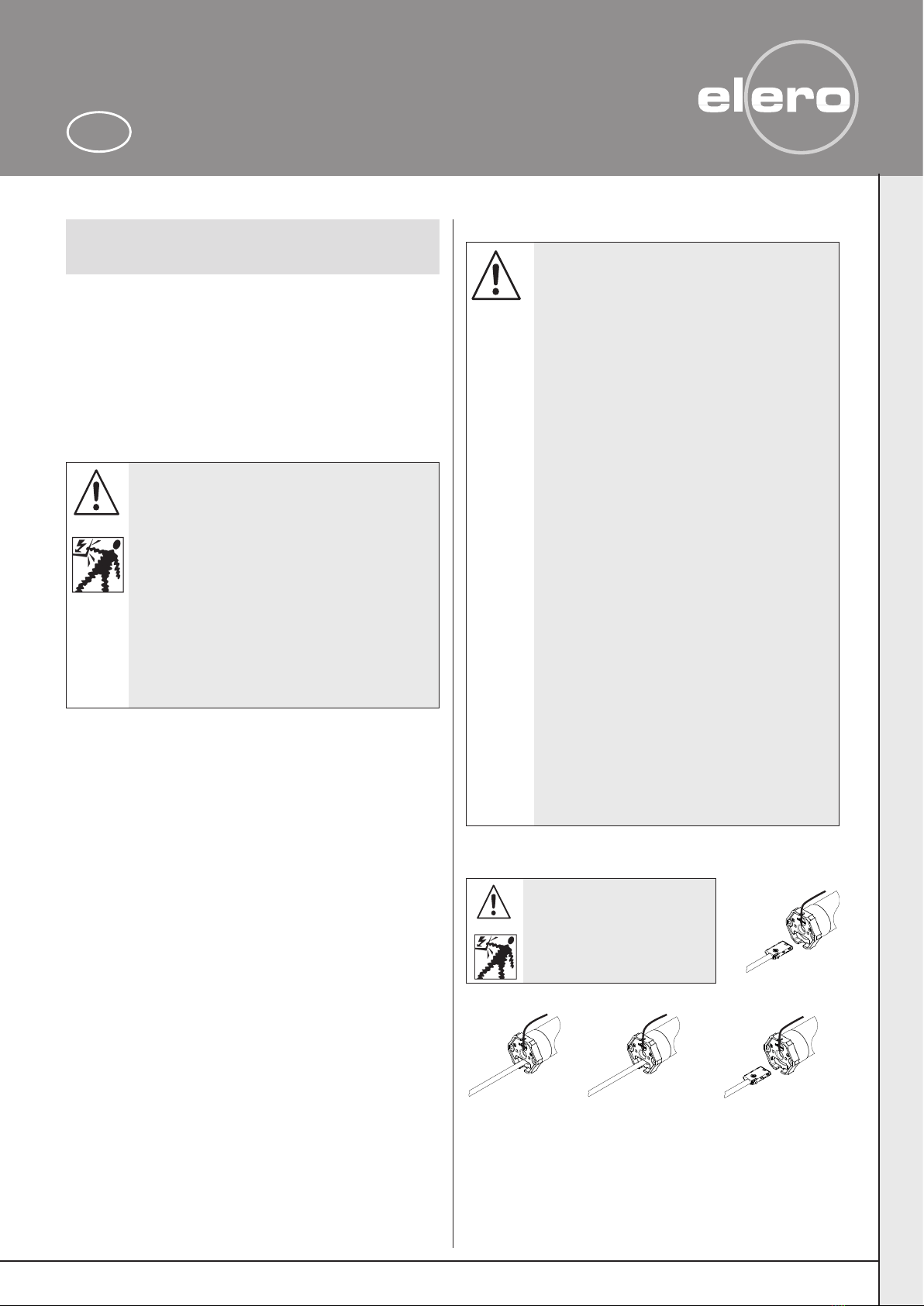
Warning!
Remove of the motor cable plug
Risk of injury due to
electric shock.
When the motor cable plug is
removed the supply line must
have no voltage.
Warning!
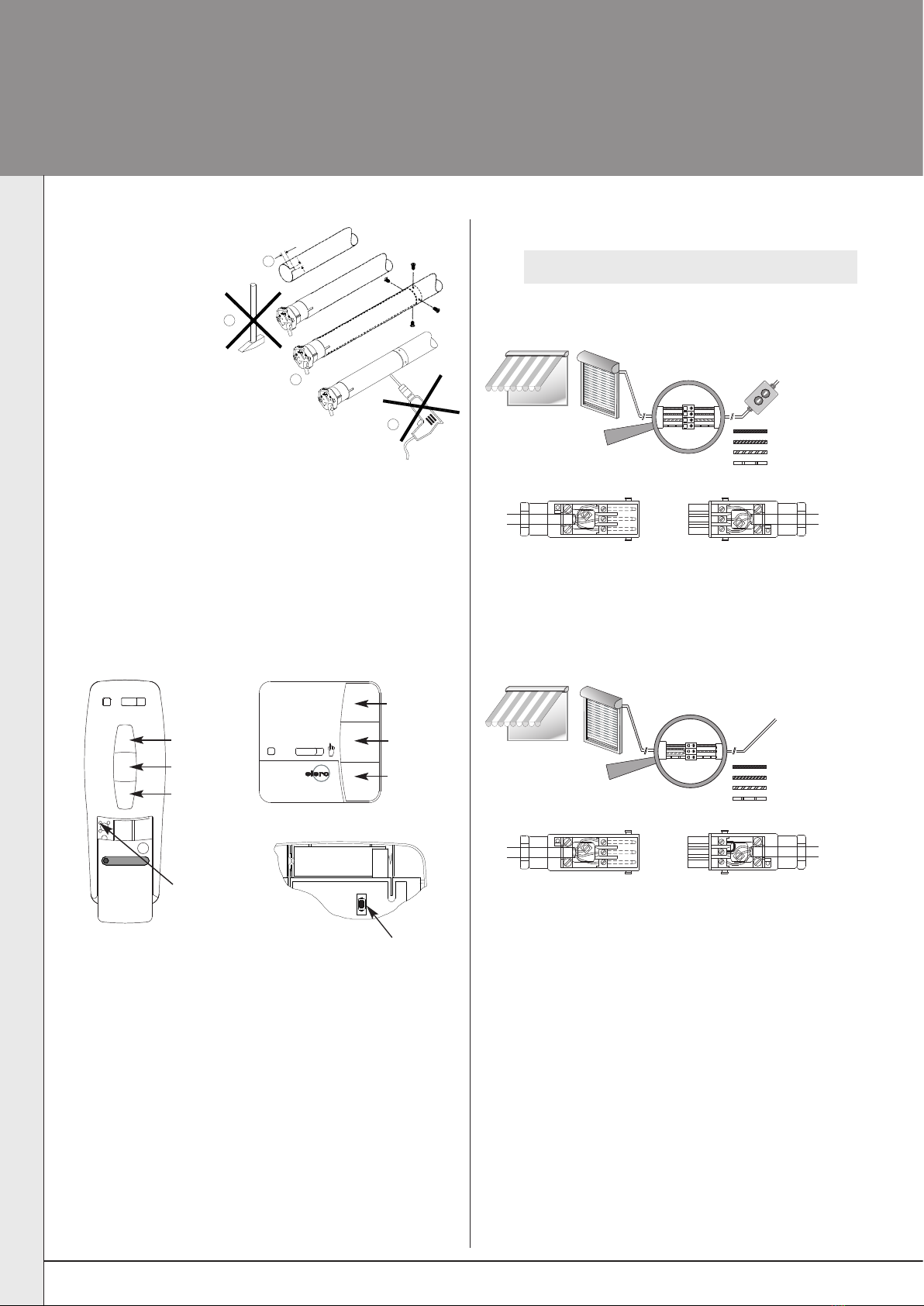
Mounting and initial operation
Explanation of ProLine buttons
Hand-held/wall transmitter
elero
Auto
LR03 (AAA)
--
Programming button P
(Back of unit)
Programming
button P
Back of wall transmitter
3
2
1
3
2
1
Mains
Assembly cable connection
(only permissible for commissioning or setting procedures)
1.
Commissioning
Mains
2.Switch on mains.
Radio connection (transmitter operation)
3
2
1
3
2
1
2. Switch on mains.
2
Note: Before you put the drive into the radio mode, you must set
the ent position.
Shaft assembly
Installation in profile tubes
X
1
On round tubes, cut
a slot in the end of
the tubes on the drive
side (width 4 mm,
length 6 mm)!
X
2Push the drive
(do not knock in)
so that the drive lug
engages in the slot.
X
3
Screw on or rivet on the coupling
(adaptor)!
X
4
Attach the hangings to the shaft!
Run in the DOWN direction if it is necessary to install
the hangings on the winding shaft.
Secure the abutment against axial shifting by riveting or bolting
the cross member.
1
4
2
3
UP button
STOP button
DOWN
button
UP button
STOP button
DOWN
button
elero
Blue (neutral wire) (1)
Black (2)
Brown (3)
Green-yellow
elero
Blue (neutral wire) (1)
Black (2)
Brown (3)
Green-yellow
Mounting and initial operation
3
Note: The maximum limit switch range is 35 revolutions of the
shaft.
Use the adjusting tool for carrying out the adjustment.
Delivery status/factory setting
-
+
-
+
Quick limit switch
adjustment
position „On“
The quick limit switch
adjustment is activated at
the factory.
Releasing screw is in the
"On" position.
The arrow of the releasing
screw points in the direc-
tion of the crown adaptor.
Limit switches are not
active in the quick limit
switch adjustment.
Adjusting tool
Adjusting tool
13 116.3801
Note: The limit switches will only work after the motor has been
installed in the shaft.
Quick limit switch adjustment
1. Attach the hangings to the shaft.
Run in the DOWN direction if it is necessary to move the
winding shaft.
2. Use the motor cable to move the hangings in the UP direction
until you reach the desired limit position.
3. Turn the releasing screw to the "Off" position.
The arrow of the releasing screw points in the direction of the
cable.
Use an adjusting tool to do so.
4. Both limit positions are now roughly pre-set.
The fine adjustment must be carried out using the individual
adjusting screws.
Only at commissioning
-
+
-
+
Quick limit switch
adjustment
position ”Off“
4
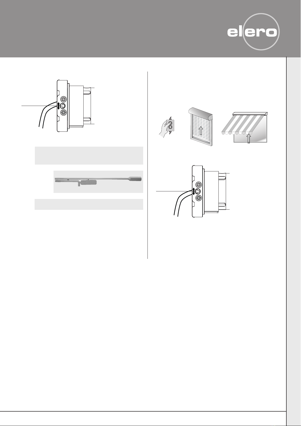
Adjustment of the end positions
Checking the end positions
Allow the drive to run alternately in both directions until the limit
switch switches off.
-
+
-
+
Limit switch
adjustment screws
1. Allow the drive to run fully in the "Down" direction.
2. Attach the roller shutter to the shaft.
3. Press the UP button on the assembly cable and keep it
depressed.
Setting of the upper end position
(Fine adjustment or end position changes) Setting the lower end position
(Fine adjustment or end position changes)
4. Turn the adjusting tool of the UP limit switch adjustment screw
in the +or –direction until the end position is reached.
One turn of the limit switch adjustment screw represents
approx. 60° of turning of the winding shaft.
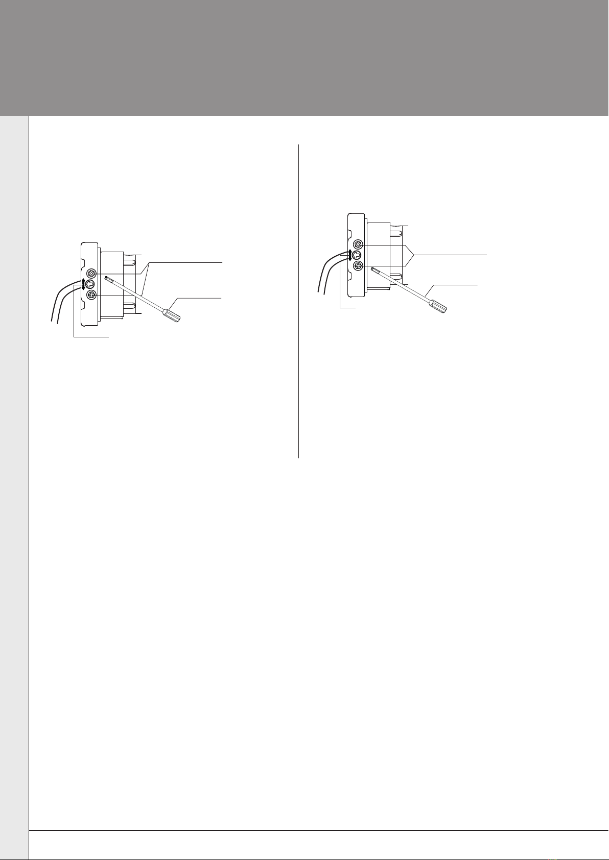
Limit switch
adjustment screws
1. Press the DOWN button on the assembly cable and keep it
depressed.
-
+
-
+
2. Turn the adjusting tool of the DOWN limit switch adjustment
screw in the +or –direction until the final end position is
reached.
One turn of the limit switch adjustment screw represents
approx. 60° of turning of the winding shaft.
The directional arrows show the corresponding travel direction of
the limit switch screws (4 mm Allen screws).
minus (–) = shorter travel
plus (+) = longer travel
Directional arrow
Adjusting tool
Adjusting tool
Directional arrow

5
Stopping the radio programming mode
Qsee transmitter instructions
STOP
elero
elero
elero
3. Press the UP button immediately after the start of upward
travel.
4. Press the DOWN button immediately after the start of
downward travel.
The drive will stop.
The transmitter is now programmed.
LR03 (AAA)
--
Auto
Auto
2. Press programming switch Pon your transmitter.
The drive runs up and down for 2 minutes.
STOP
elero
elero
elero
3. Press the UP button immediately after the start of upward
travel.
4. Press the DOWN button immediately after the start of
downward travel.
The drive will stop.
The transmitter is now programmed.
LR03 (AAA)
--
Auto
Auto
2. Press simultaneously:
UP and DOWN buttons and programming button Pon the
programmed transmitter for min. 3 sec.
The drive runs up and down for 2 minutes.
Auto
min. 3 sec.
Programmed transmitter
New transmitter
New transmitter
+
STOP
STOP
Deletion of individual transmitters
Qsee instructions for the control unit
Deletion of all transmitters
Qsee instructions for the control unit
STOP STOP
STOP
STOP
Programming the transmitter/
Programming further transmitters
Programming the transmitter
Condition: The drive is in radio mode.
The end positions must have been programmed.
If the end positions have not been programmed,
remove the blind from the shaft.
When the mains has been switched off for a short time,
the drive is ready to be programmed for 5 minutes.
1. Switch off/on mains.
Programming procedure for other transmitters
Programming procedure possible for max. 16 transmitters.
In order to program further transmitters, start with the new
transmitter at 1
or
1. Switch off/on mains

6
Notes on troubleshooting
Fault Possible cause Remedy
• Radio programming mode • Faulty connection • Check connection
does not start • Drive not connected to mains • Check mains voltage
• Time frame already expired (5 min) • Interrupt mains voltage briefly
• Thermostat has triggered • Allow drive to cool down
• Radio transmitter has no battery • Check transmitter (LED must be illuminated)
• Radio transmitter not in • UP/DOWN button pressed too late. • Restart radio programming mode
programming mode Note time frame (1 sec.)
• Sender ist bereits eingelernt • Push STOP button
• Drive runs only in one direction • Faulty connection • Check connection
• The drive does not switch off • Limit switch ring is not being driven • Readjust installation and limit switches via
via the limit switch the limit switch adjusting screws
• Drive does not react • Limit switch is not adjusted • Set limit switch
• Drive is no longer reacting • Wrong connection • Readjust connection
• Thermostat has triggered • Allow drive to cool down
Troubleshooting

7

Technical parameters subject to change
08/09
20
NRG Automation Ltd.
Foundry Lane – Halebank
Widnes, Cheshire WA8 8TZ
Tel. (44) 87024042 19
Fax (44) 87024040 86
www.elero.com
elero GmbH
Antriebstechnik Linsenhofer Straße 59–63
D-72660 Beuren
Telefon (070 25) 13-01
Telefax (07025) 13-212
www.elero.com
Table of contents
Other elero Engine manuals


Popular Engine manuals by other brands


Vanguard
Vanguard Series 432447 Operating and maintenance instructions

VOGELS
VOGELS VGI Hardware manual

Corsair
Corsair M25 manual

Oriental motor
Oriental motor BLM operating manual

E-MAG
E-MAG LYCOMING 200-6XL Series Installation and operating guide

Oriental motor
Oriental motor K II S Series operating manual

Power Fist
Power Fist 8714040 user manual

AOK
AOK AM24 PLUS manual

Hobby King
Hobby King XYZ 53 STS Service manual

woodmizer
woodmizer D17 Safety, Operation, Maintenance & Parts Manual

Crestron Electronics
Crestron Electronics CSM-QMTDC Series quick start

Sea-doo
Sea-doo Rotax 1503 4-Tec 2005 Engine shop manual