elero JA 10 Soft User manual
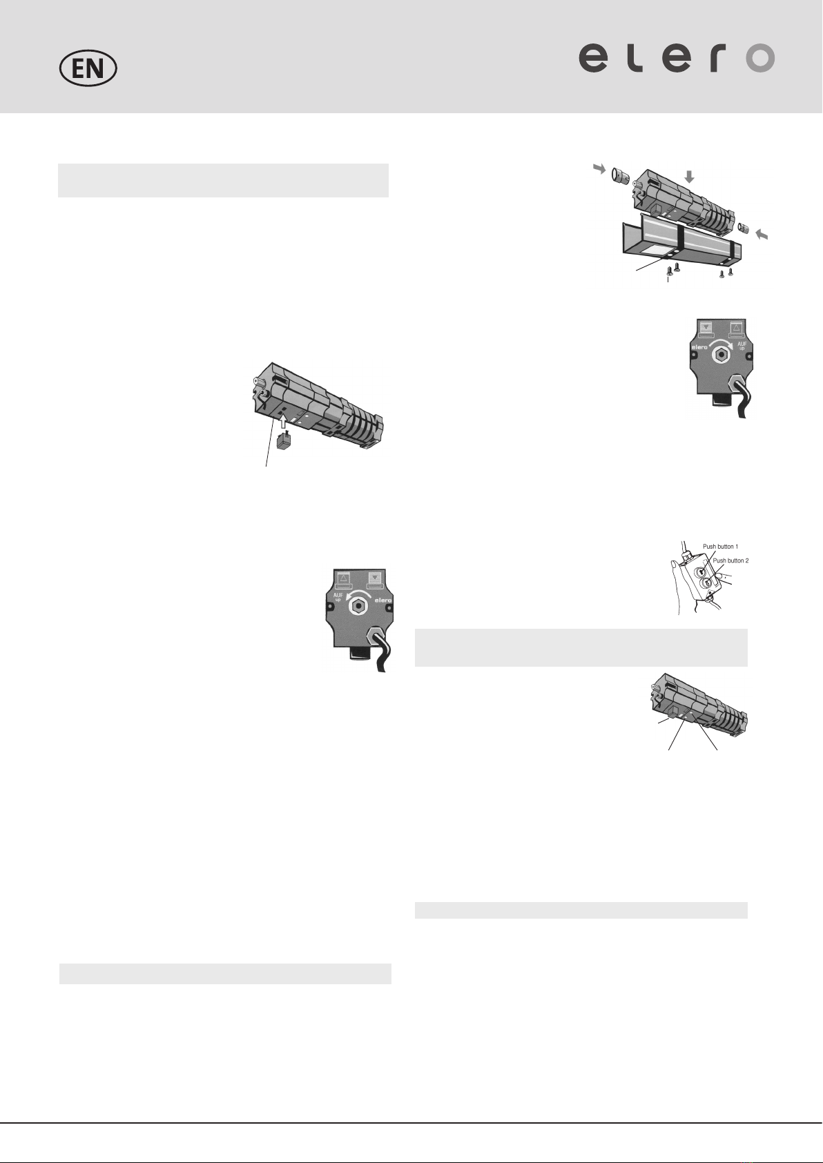
Installation in headpiece
Installation instructions:
•
Install drive without restraint, in correct
position (safety cut-out showing
downwards), and properly aligned with
the shafts in the venetian blind head.
•
Impacts (e.g. hammer blows) are not
permitted on drive, shaft or coupling.
•
The axle height of the drive is 27.5 mm.
See JA accessories for dampers for different
bearing blocks axle heights.
•
Make sure that the shaft is not radially loaded.
• Please put equal load on both drive shaft outputs on
the motor.
•
Make electrical connection with installation cable (arti-
cle number 23 246.0001) and check the turning direc-
tion of the drive shaft according to the direction advice
on the front of the limit switch housing. Travel to the
lower end position again with the DOWN pushbutton.
• Couple drive to shaft.
Advice
• Valid only with right hand installation
• In the case of left hand installation the colour assignment is
exactly reversed.
Safety
cutout
Adjustment
push button
(white) DOWN
Adjustment
push button
(orange) UP
damper
cuntersunk bolt with
cross recess H no. 3
After the venetian blind motor has been installede, attach
these instructions to the cable for the use of the electrician.
Mounting instructions
Mounting of the safety cut-out „right hand installation“
Remove label on the bottom side of the limit switch housing and
insert the safety cut-out with orange or black cap in the openings
and engage it in such a way that the orange or black pressure pin
points towards the side of the orange adjustment push-button UP.
If the supplied safety cut-out cannot be used, e.g. due to lack of
space, then the label must not be removed since it protects the
inside of the limit switch against dirt.
Please check the function of the safety cut-out. Incorrect
installation may lead to damage.
If the safety cut-out is not long enough,
it can be extended by 10 mm at a time
with the safety cut-out extension
(article number 16 101.4501).
(Maximum of 3 safety cut-out
extensions can be plugged on).
Insert the blade of a small flat
screwdriver into one of the grooves
on the orange cover and by pressing the blade towards the middle
of the safety cut-out, lever off the cover. Clip on the extension and
then clip on the cover again.
Mounting of the safety cut-out „left hand installation“
(special Accessory)
When installing the JA drive as a left-hand system
the arrangement of the microswitches inside the limit
switch housing automatically swaps over the UP and
DOWN movments.
This means that the safety cut-out with the white cap
(article number 26 200.1101) must be used.
This safety cut-out must be inserted and clipped
into the openings of the limit switch housing so that the „white“
pressure pin points to the side of the „white“ adjustment push
button. The label L provided with the directional advice, should
then be stuck over the existing label on the front.
Mounting of the QuickSnap coupling for JA
1. Apply coupling at an angle whilst observing the position of the
coupling with respect to the shaft: The stop spring should slide
on the upper surface of the hexagonal shaft.
2. Push coupling a little further until the spring audibly latches into
the groove (click).
3. If the groove is covered by a bearing or lockwasher, the
hexagonal shaft can be correspondingly pushed back until the
coupling spring latches into place.
4. By pulling it by jerks check that the coupling is securely seated.
Dismantling of the QuickSnap coupling for JA
Do not forcibly remove the coupling.
1. Lift up the motor coupling retaining spring on the shaft with a
small screwdriver.
2. Pull off the coupling.
JA 10 Soft Venetian Blind Motors
35 093.0001
removable label
Setting the lower end position:
It is not normally necessary to set the lower end position since the
ventian blind drives are set to the lower end position in the factory.
If it is necessary however the setting takes place in the same way as
for the upper end position.
• Move venetian blind downwards with the corresponding push
button.
• Simultaneously press the white adjustment button and hold it
down for at least 5 seconds.
Advice:
Compare with setting the upper end position.
• With the help of the installation cable travel directly to the lower
end position (fine adjustment by means of inching operation with
the installation cable).
•
By changing the direction of travel the adjustment button is
automatically unlatched and the lower end position is then set.
Readjustments:
If the respective end position is not accurately set or if the end
positions have changed due to changed winding behaviour of
the venetian blind, then the end positions will have to be reset as
described above.
With the help of the installation cable the venetian blind should be
moved back to about 0.5 m before the desired end position.
.
The limit switch range is 85 revolutions of the shaft.
168029001_EN_0612
Setting instructions
Venetian blind drives are supplied from the factory already set
to the lower end position. Connect installation cable to venetian
blind drive.
Connect installation cable to venetian blind drive.
Setting the upper end position:
• Move venetian blind upwards with the
corresponding push button.
• Press in the orange adjustment button while it is
moving up and hold it in for at least 5 seconds
(adjustment button stays latched in).
Advice
This must have taken place at latest 0.5 m before reaching
the end position. After pressing the admustment button it must
stay latched in.
• With the help of the installation cable
travel directly to the upper end position
(fine adjustment by means of inching
operation with the installation cable).
• By changing the direction of travel the
adjustment button is automatically unlatched
and the upper end position is then set.

JA 10 Soft DC Venetian Blind Motors
Technische Änderungen vorbehalten
Warnung!
Connection example
Push-button / Switch
12V/DC
DC drive
M
k1
k2
k1 k2
red
brown
white
black
connection box
lever
Safety cut-out
Switches, push-buttons or circuits, which simultane-
ously permit up and down commands, must not be
connected.
When changing direction the drive must first be dead
for at least 0.5 seconds.
One ore more venetian blind motor(s)
Please take care of ot the operating instructions!
elero GmbH
Antriebstechnik Maybachstr. 30
73278 Schlierbach Fon: +49 (0) 7021 9539-0
Fax: +49 (0) 7021 9539-212 [email protected]
www.elero.com
Important safety advices!
Observe the following instructions:
The connections to the 12 V mains must bei made by authorised
specialist personnel.
The regulations for wet an damp rooms according to VDE 0100
must be followed when making the connections.
Drive only to be operated on 12V DC power.
Only use unmodified original elero electrical parts.
The drive is suitable only for interior and exterior venetian blinds.
For other appications please contact the manufacturer.
Keep people away from the system until it is stationary.
When working on the system (servicing, cleaning windows etc.),
always separate it from the mains supply.
Assembly
• The drive must be fixed in such a way that it is not a danger to
personnel.
• Before installing the drive, all lines and equipment, which are
not required for operation, must be removed form the site.
• During installation, during operation and when work is carried
out on the system, the option to separate all poles from the
mains must always exist.
• If the drive is controlled by a switch with OFF pre-setting (dead
man‘s button), the pushbutton must be fitted at a height of
more than 1.50 m and separated from the moving parts. The
travel range of the systems must always be visible duringope-
ration.
• Moving parts in a drive, which are below 2,5 m, muste be guar-
ded.
• For drives supplied without a driven part the design torque and
the design operating time must agree with the properties of the
driven parts.
Please note the technical data on the type plate.
• The guarantee will lapse if the electrical connections are incor-
rect, if the installation work has been carried out imporperly
or if repairs, interventions and changes have been made by
unauthorised people!
• The drive may only be installed in such a way that it is not
directly subject to the influence of the weather.
• Note the technical data for the motor.
• Keep children away from the controller and remote controller.
• When installing JA drives in systems, devices or machines
the installer must ensure that electromagnetic compatibility is
maintained.
• The system should be checked at regular intervals for wear or
damage.
• Do not install drives in surroundings which are at risk of explo-
sion or in mobile appliances (e.g. motor vehicles).
Terminal connections
1 brown Up
2 white +12 V
3 red Down (red on wire, blue on plug)
4 black -0 V
Other elero Engine manuals


Popular Engine manuals by other brands


Vanguard
Vanguard Series 432447 Operating and maintenance instructions

Oriental motor
Oriental motor K II Series operating manual

AutomationDirect
AutomationDirect IronHorse HGR-37-005-A user manual

Powerline
Powerline SKID SERIES Operator's manual

Oriental motor
Oriental motor FH Series operating manual

XPower
XPower XA Series operating instructions