3
User's Manual | VP070-M8M
Table of Contents
Chapter 1 - Introduction................................................................................................................6
Overview.................................................................................................................................. 6
Bottom View.....................................................................................................................6
Back View.........................................................................................................................6
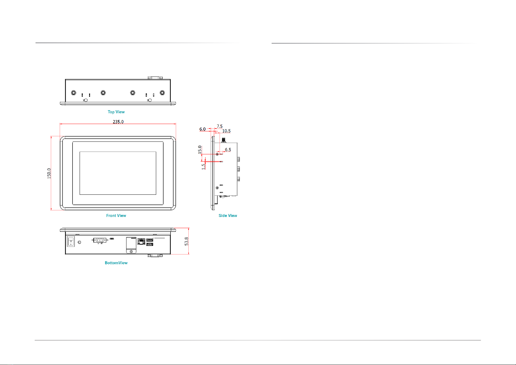
Dimensions ............................................................................................................................. 7
Key Features ........................................................................................................................... 7
Specifications ......................................................................................................................... 8
Chapter 2 - Hardware Installations............................................................................................10
Removing the Chassis Cover ..............................................................................................10
Installing an M.2 Card .........................................................................................................12
Installing an Antenna ...........................................................................................................13
Mounting Options.................................................................................................................14
Wall Mount .....................................................................................................................14
Panel Mount...................................................................................................................15
Chapter 3 - System Settings ......................................................................................................16
System Layout......................................................................................................................16
Power Board...................................................................................................................16
System Board.................................................................................................................17
System Board - uSD Card Slot......................................................................................18
Jumper Settings- Power Board ...........................................................................................19
Host Bus Communication (JP3, JP4)..........................................................................19
Remote Switch High/Low Active (JP2) .......................................................................19
SW1.................................................................................................................................20
24V / 12V Select............................................................................................................20
POWER ON Delay Switch ..............................................................................................20
POWER OFF Delay Switch.............................................................................................20
POWER ON Delay Time Select .....................................................................................21
POWER OFF Delay Time Select....................................................................................21
Jumper Settings- System Board .........................................................................................22
Boot Config (JP1)..........................................................................................................22
LED Backlight (JP5) ......................................................................................................22
Pin Assignment- Power Board ............................................................................................23
12V DC-Out (CN3)..........................................................................................................23
9V~36V In (J1) ..............................................................................................................23
MCU Connector (J2) .....................................................................................................24
MCU Debug (JP1)..........................................................................................................24
Remote Switch (J3).......................................................................................................25
Pin Assignment- System Board ..........................................................................................26
COM1 Debug (J10)........................................................................................................26
USB2_3 (UBJ1) ..............................................................................................................26
Speaker (AUJ1)..............................................................................................................27
Audio (AUJ2)..................................................................................................................27
DIO (IOJ1).......................................................................................................................28
I2C (J8)...........................................................................................................................28
VP IO (VPJ1) ..................................................................................................................29
LVDS (J11) .....................................................................................................................30