Elettronica Santerno SINUS K Series Owner's manual

•15R0095B2 •
SINUS K
FULL DIGITAL INVERTER
PROGRAMMING
MANUAL
R02 Updated 20/04/05
Software Version
IFD V2.03x / VTC V2.03x
Supersedes R01 03/12/04
Elettronica Santerno S.p.A.
Via G. Di Vittorio, 3 – 40020 Casalfiumanese (BO) Italy
Tel. +39 0542 668611 – Fax +39 0542 668622
www.elettronicasanterno.it [email protected]
•This manual is integrant and essential to the product. Carefully read the instructions contained herein as they
provide important hints for use and maintenance safety.
•This device is to be used only for the purposes it has been designed to. Other uses should be considered improper
and dangerous. The manufacturer is not responsible for possible damages caused by improper, erroneous and
irrational uses.
•Elettronica Santerno is responsible for the device in its original setting.
•Any changes to the structure or operating cycle of the device must be performed or authorized by the Engineering
Department of Elettronica Santerno.
•Elettronica Santerno assumes no responsibility for the consequences resulting by the use of non–original spare–
parts.
•Elettronica Santerno reserves the right to make any technical changes to this manual and to the device without prior
notice. If printing errors or similar are detected, the corrections will be included in the new releases of the manual.
•Elettronica Santerno is responsible for the information contained in the original version of the Italian manual.
•The information contained herein is the property of Elettronica Santerno and cannot be reproduced. Elettronica
Santerno enforces its rights on the drawings and catalogues according to the law.
English

PROGRAMMING SINUS K
MANUAL
2/226
GENERAL FEATURES
PRODUCTS COVERED IN THIS MANUAL
This Programming Manual covers all inverters of the SINUS K, SINUS BOX K and SINUS CABINET K series with supply
voltage ranging from 200Vac to 690Vac: from Size S05 to Size S70 with IFD application software; supply voltage
ranging from 200Vac to 500Vac: from Size S05 to Size S50 with VTC application software.
For LIFT software (lift applications) a separate Programming Manual is available.

SINUS-K PROGRAMMING
MANUAL
3/226
0. TABLE OF CONTENTS
0.1. CHAPTERS
GENERAL FEATURES ......................................................................................................................2
PRODUCTS COVERED IN THIS MANUAL............................................................................................................. 2
0. TABLE OF CONTENTS ............................................................................................................3
0.1. CHAPTERS ............................................................................................................................................ 3
0.2. FIGURES............................................................................................................................................... 6
1. INPUT SIGNALS AND OUTPUT SIGNALS ...............................................................................7
1.1. DIGITAL INPUTS ................................................................................................................................... 7
1.1.1. Enable (Terminal 6) .......................................................................................................................... 8
1.1.2. Start (Terminal 7).............................................................................................................................. 8
1.1.3. Reset (Terminal 8)............................................................................................................................. 8
1.1.4. MDI1÷5 (Terminals 9, 10, 11, 12, 13)............................................................................................... 9
1.1.4.1. Multifrequency/Multispeed– Programmable Reference Levels ................................................... 10
1.1.4.2. Up/Down.............................................................................................................................. 11
1.1.4.3. CW/CCW – Reverse Command ............................................................................................. 11
1.1.4.4. DCB – Direct Current Braking ................................................................................................ 11
1.1.4.5. Multiramp ............................................................................................................................. 11
1.1.4.6. VAR% – Reference Variation Percent (IFD SW only) .................................................................. 12
1.1.4.7. V/F2 – Second Voltage/Frequency Pattern (IFD SW only) ......................................................... 12
1.1.4.8. Ext A – External Alarm............................................................................................................ 13
1.1.4.9. REV – Reverse Rotation........................................................................................................... 13
1.1.4.10. A/M – Automatic/Manual .................................................................................................. 13
1.1.4.11. Lock ................................................................................................................................. 13
1.1.4.12. Stop ................................................................................................................................. 13
1.1.4.13. Slave (VTC SW only).......................................................................................................... 14
1.1.4.14. Motor Thermal Protection Input (PTC)................................................................................. 14
1.1.4.15. 15 Loc/Rem......................................................................................................................14
1.1.4.16. Fire Mode (IFD SW only).................................................................................................... 14
1.2. DIGITAL OUTPUTS.............................................................................................................................. 15
1.2.1. Open Collector Output ................................................................................................................... 15
1.2.2. Relay Outputs................................................................................................................................. 16
1.3. ANALOG INPUTS ............................................................................................................................... 17
1.3.1. Auxiliary analog input..................................................................................................................... 17
1.4. ANALOG OUTPUTS FEATURES............................................................................................................ 18
1.4.1. Analog Outputs.............................................................................................................................. 18
2. MAIN REFERENCE................................................................................................................19
3. PROGRAMMABLE FUNCTIONS ............................................................................................24
3.1. VOLTAGE/FREQUENCY PATTERN (V/F PATTERN) (IFD SW only)............................................................ 24
3.2. CARRIER FREQUENCY (IFD SW only) ................................................................................................... 26
3.3. SLIP COMPENSATION (IFD SW only) ................................................................................................... 28
3.4. SPEED SEARCHING (IFD SW only)........................................................................................................ 28
3.5. FIRE MODE FUNCTION (IFD SW only) ................................................................................................. 33
3.6. SENSORLESS VECTOR CONTROL (VTC SW only) ................................................................................. 34
3.7. TORQUE CONTROL (VTC SW only)..................................................................................................... 35
3.8. POWER DOWN .................................................................................................................................. 35
3.9. DC BRAKING...................................................................................................................................... 37
3.9.1. DC Braking at Stop......................................................................................................................... 37
3.9.2. DC Braking at Start ........................................................................................................................ 38
3.9.3. DC Braking Command Sent Via Terminal Board .............................................................................. 39
3.9.4. DC Braking Holding (IFD SW only) .................................................................................................. 41
3.10. MOTOR THERMAL PROTECTION ........................................................................................................42
3.11. PROHIBIT FREQUENCIES/SPEEDS........................................................................................................ 43
3.12. PID REGULATOR................................................................................................................................. 44
3.12.1. General Features and output operation....................................................................................... 44
3.12.2. Managing PID Regulator Input Signals ........................................................................................44
3.12.3. PID regulator error inversion....................................................................................................... 45
4. PROGRAMMING PARAMETERS .......................................................................................48
4.1. MAIN MENUS..................................................................................................................................... 48
4.2. SUBMENUS ........................................................................................................................................ 50

PROGRAMMING SINUS K
MANUAL
4/226
5. COMMON MENUS TO IFD SW AND VTC SW ...................................................................... 52
5.1. COMMANDS MENU........................................................................................................................... 52
5.1.1. Keypad submenu ........................................................................................................................... 52
5.1.2. Restore Default Submenu................................................................................................................ 54
5.1.3. Save User’s Parameters Submenu ................................................................................................... 55
5.2. INVERTER RATINGS ............................................................................................................................ 56
6. LIST OF IFD SW PARAMETERS ....................................................................................... 57
6.1. MENU AND SUBMENU TREE STRUCTURE – IFD SW............................................................................. 57
6.2. MEASURE/PARAMETER MENU ............................................................................................................. 59
6.2.1. Measure Submenu ......................................................................................................................... 59
6.2.2. Key Parameter ............................................................................................................................... 62
6.2.3. Ramps Submenu ............................................................................................................................ 62
6.2.4. Reference Submenu........................................................................................................................ 65
6.2.5. Output Monitor Submenu ............................................................................................................... 68
6.2.6. Multifrequency Submenu ................................................................................................................ 70
6.2.7. Prohibit Frequencies Submenu ........................................................................................................ 73
6.2.8. Digital Output Submenu................................................................................................................. 75
6.2.9. Ref. Var% Submenu........................................................................................................................ 86
6.2.10. Pid Regulator Submenu.............................................................................................................. 88
6.3. CONFIGURATION MENU................................................................................................................... 90
6.3.1. Carrier Frequency Submenu ........................................................................................................... 90
6.3.2. V/f Pattern Submenu ...................................................................................................................... 91
6.3.3. Operation Method Submenu .......................................................................................................... 95
6.3.4. Power Down Submenu ................................................................................................................... 99
6.3.5. Limits Submenu............................................................................................................................ 100
6.3.6. Autoreset Submenu ...................................................................................................................... 102
6.3.7. Special Function Submenu............................................................................................................ 103
6.3.8. Motor Thermal Protection Submenu .............................................................................................. 108
6.3.9. Slip Compensation Submenu........................................................................................................ 109
6.3.10. D.C. Braking Submenu ............................................................................................................ 110
6.3.11. Serial Network Submenu.......................................................................................................... 112
6.4. CONFIGURATION TABLE FOR IFD SW PARAMETERS ......................................................................... 114
7. LIST OF VTC SW PARAMETERS .................................................................................... 115
7.1. MENU AND SUBMENU TREE STRUCTURE – VTC SW.......................................................................... 115
7.2. MEASURE/PARAMETER MENU ........................................................................................................... 117
7.2.1. Measure Menu............................................................................................................................. 117
7.2.2. Key Parameter ............................................................................................................................. 120
7.2.3. Ramps Submenu .......................................................................................................................... 121
7.2.4. Reference Submenu...................................................................................................................... 123
7.2.5. Output Monitor Submenu ............................................................................................................. 126
7.2.6. Multispeed Submenu.................................................................................................................... 130
7.2.7. Prohibit Speeds Submenu ............................................................................................................. 133
7.2.8. Digital Output Submenu............................................................................................................... 134
7.2.9. PID Regulator Submenu................................................................................................................ 143
7.2.10. Speed Loop Submenu.............................................................................................................. 146
7.2.11. Torque Ramps Submenu .......................................................................................................... 147
7.3. CONFIGURATION MENU................................................................................................................. 148
7.3.1. Vtc Pattern Submenu .................................................................................................................... 148
7.3.2. Operation Method Submenu ........................................................................................................ 150
7.3.3. Power Down Submenu ................................................................................................................. 154
7.3.4. Limits Submenu............................................................................................................................ 156
7.3.5. Autoreset Submenu ...................................................................................................................... 157
7.3.6. Special Function Submenu............................................................................................................ 158
7.3.7. Motor Thermal Protection Submenu .............................................................................................. 162
7.3.8. D.C. Braking Submenu................................................................................................................. 163
7.3.9. Serial Network Submenu .............................................................................................................. 165
7.4. CONFIGURATION TABLE FOR VTC SW PARAMETERS ........................................................................ 167
8. DIAGNOSTICS ................................................................................................................ 168
8.1. INVERTER OPERATING CONDITIONS ............................................................................................... 168
8.2. ALARM MESSAGES ........................................................................................................................... 172
8.3. DISPLAY LED .................................................................................................................................... 175
9. SERIAL COMMUNICATION .......................................................................................... 176
9.1. GENERAL FEATURES......................................................................................................................... 176
9.2. MODBUS–RTU PROTOCOL .............................................................................................................. 176

SINUS-K PROGRAMMING
MANUAL
5/226
9.3. GENERAL FEATURES and EXAMPLES .................................................................................................. 178
9.3.1. Scaling......................................................................................................................................... 179
9.3.2. Bit Parameters .............................................................................................................................. 180
9.3.3. Support Variables ......................................................................................................................... 180
10. PARAMETERS SENT VIA SERIAL LINK (IFD SW) .....................................................181
10.1. MEASURE PARAMETERS (Mxx) (Read Only) ......................................................................................... 181
10.2. PROGRAMMING PARAMETERS (Pxx) (Read/Write)............................................................................... 182
10.2.1. Ramps Menu P0x – P1x ............................................................................................................ 182
10.2.2. Reference Menu P1x – P2x........................................................................................................ 183
10.2.3. Output Monitor Menu P3x ........................................................................................................ 184
10.2.4. Multifrequency Menu P3x – P5x................................................................................................. 185
10.2.5. Prohibit Frequency Menu P5x.................................................................................................... 185
10.2.6. Digital Outputs Menu P6x – P7x................................................................................................ 186
10.2.7. % Reference Var. Menu P7x – P8x ............................................................................................. 187
10.2.8. P.I.D. Regulator Menu P8x – P9x ............................................................................................... 187
10.3. CONFIGURATION PARAMETERS (Cxx) (Read/Write with inverter disabled, Read Only with inverter in RUN
mode) ........................................................................................................................................................ 188
10.3.1. Carrier Frequency Menu C0x.................................................................................................... 188
10.3.2. V/F Pattern Menu C0x – C1x .................................................................................................... 189
10.3.3. Operation Method Menu C1x – C2x ......................................................................................... 189
10.3.4. Power Down Menu C3x............................................................................................................ 191
10.3.5. Limits Menu C4x ...................................................................................................................... 192
10.3.6. Autoreset Menu C4x................................................................................................................. 193
10.3.7. Special Functions Menu C5x – C6x ........................................................................................... 193
10.3.8. Motor Thermal Protection Menu C6x......................................................................................... 194
10.3.9. Slip Compensation Menu C7x .................................................................................................. 194
10.3.10. D.C. Braking Menu C8x ........................................................................................................... 195
10.3.11. Serial Link Menu C9x ............................................................................................................... 195
10.4. SPECIAL PARAMETERS (SPxx) (Read Only) ........................................................................................... 196
10.5. SPECIAL PARAMETERS (SWxx) (Read Only).......................................................................................... 198
10.6. SPECIAL PARAMETERS (SPxx) (Write Only)........................................................................................... 198
11. PARAMETERS SENT VIA SERIAL LINK (VTC SW) ..............................................................202
11.1. MEASURE PARAMETERS (Mxx) (Read Only) ......................................................................................... 202
11.2. PROGRAMMING PARAMETERS (Pxx) (Read/Write)............................................................................... 203
11.2.1. Ramps Menu P0x – P1x ............................................................................................................ 203
11.2.2. Reference Menu P1x – P2x........................................................................................................ 204
11.2.3. Output Monitor Menu P2x – P3x ............................................................................................... 205
11.2.4. Multispeed Menu P3x – P4x ...................................................................................................... 206
11.2.5. Prohibit Speed Menu P5x.......................................................................................................... 206
11.2.6. Digital Outputs Menu P6x – P7x................................................................................................ 207
11.2.7. P.I.D. Regulator Menu P8x – P9x ............................................................................................... 208
11.2.8. Speed Loop Menu P10x............................................................................................................ 208
11.2.9. Torque Ramp Menu P10x ......................................................................................................... 208
11.3. CONFIGURATION PARAMETERS (Cxx) (Read/Write with inverter disabled, Read Only with inverter in RUN
mode) ........................................................................................................................................................ 209
11.3.1. VTC Pattern Menu C0x – C1x ................................................................................................... 209
11.3.2. Operation Method Menu C1x – C2x ......................................................................................... 210
11.3.3. Power Down Menu C3x............................................................................................................ 212
11.3.4. Limits Menu C4x ...................................................................................................................... 213
11.3.5. Autoreset Menu C4x................................................................................................................. 213
11.3.6. Special Functions Menu C5x – C6x ........................................................................................... 214
11.3.7. Motor Thermal Protection Menu C6x......................................................................................... 215
11.3.8. D.C. Braking Menu C7x ........................................................................................................... 215
11.3.9. Serial Link Menu C8x ............................................................................................................... 216
11.4. SPECIAL PARAMETERS (SPxx) (Read Only) ........................................................................................... 216
11.5. SPECIAL PARAMETERS (SWxx) (Read Only).......................................................................................... 218
11.6. SPECIAL PARAMETERS (SPxx) (Write Only)........................................................................................... 219
12. SELECTING THE APPLICATION SW (IFD SW or VTC SW) ................................................222
12.1. FLASH PROGRAMMING .................................................................................................................... 222
12.2. DSP PROGRAMMING........................................................................................................................ 222
12.3. SELECTING THE APPLICATION SOFTWARE........................................................................................ 223
12.4. ALARMS RELATING TO SW SELECTION PROCEDURE ......................................................................... 226

PROGRAMMING SINUS K
MANUAL
6/226
0.2. FIGURES
Figure 1: Digital input control modes ....................................................................................................................... 7
Figure 2: Connecting a relay to the OPEN COLLECTOR output............................................................................... 15
Figure 3: Parameters relating to auxiliary input processing...................................................................................... 17
Figure 4: Parameters relating to main reference processing. ................................................................................... 20
Figure 5: Block diagram of main reference processing for IFD SW........................................................................... 22
Figure 6: Block diagram of main reference processing for VTC SW. ........................................................................ 23
Figure 7: Parameters relating to the voltage/frequency pattern................................................................................ 24
Figure 8: Carrier frequency based on output frequency........................................................................................... 27
Figure 9 Carrier frequency with the........................................................................................................................ 27
Figure 10: Output frequency and motor rpm during speed searching (C55 = [YES] or C55 = [YES A]) activated by the
ENABLE command. tOFF < tSSdis (C56) or C56 = 0. .......................................................................................... 29
Figure 11: Frequency, rpm of the inverter motor during speed searching (power off, C55 =[YES A]) due to the
adjustment of the ENABLE command. t1+ t2< tSSdis (C56) or C56 = 0. ........................................................... 30
Figure 12: Output frequency, rpm, inverter locked, reset and ENABLE commands during speed searching due to an
alarm trip (C55 = [YES] or C55 = [YES A]). tOFF < tSSdis (C56) or C56 = 0........................................................ 31
Figure 13: Output frequency, rpm, inverter condition, power supply, reset and ENABLE commands when speed
searching is due to an alarm reset and to voltage removal from the inverter (C55 = [YES A]). t1+ t2< tSSdis (C56)
or C56 = 0................................................................................................................................................... 32
Figure 14: Equivalent circuit of the asynchronous machine..................................................................................... 34
Figure 15: Output frequency/speed and DC bus voltage of the inverter (VDC LINK) in case of mains failure with a higher
(a) or shorter (b) duration than the motor stop time......................................................................................... 36
Figure 16: Output frequency/speed and DC braking current when the DC BRAKING AT STOP function is enabled. ... 37
Figure 17: Output frequency/speed and braking DC current when the DC BRAKING AT START function is active....... 38
Figure 18: Output frequency and braking direct current when the DC braking command is activated. ...................... 40
Figure 19: Output frequency and braking DC when the DC braking holding function is active.................................. 41
Figure 20: Motor heating with two different, constant current values (I01 and I02) and pick–up current It of the
protection with respect to the frequency/speed depending on the configuration of parameter C70 (IFD SW) or
C65 (VTC SW)............................................................................................................................................... 42
Figure0 21: Prohibit frequency/speed ranges. ........................................................................................................ 43
Figure 22: PID regulator block diagram (common section)...................................................................................... 46
Figure 23: PID regulator block diagram (relating to IFD SW only)............................................................................ 47
Figure 24: PID regulator block diagram (relating to VTC SW only)........................................................................... 47
Figure 25: Digital output programming with “REFERENCE LEVEL” programmed P60-P62 ......................................... 82
Figure 26: MDO with P60-P62 programmed as 1-FREQUENCY SPEED LEVEL 2-FORWARD RUNNING, 3-REVERSE
RUNNING .................................................................................................................................................... 82
Figure 27: MDO with P60-P62 programmed as Fout/Nout ok................................................................................. 83
Figure 28: MDO with P60-P62 programmed as current level .................................................................................. 83
Figure 29: MDO with P60-P62 programmed as “PID ERROR” ................................................................................. 84
Figure 30: MDO with P60-P62 programmed as “PID MAX OUT.............................................................................. 84
Figure 31: MDO with P60-P62 programmed as “PID OUT MIN”............................................................................. 85
Figure 32: MDO with P60-P62 programmed as “FB MAX”...................................................................................... 85
Figure 33: MDO with P60-P62 programmed as “FB MIN” ...................................................................................... 86

SINUS-K PROGRAMMING
MANUAL
7/226
1. INPUT SIGNALS AND OUTPUT SIGNALS
1.1. DIGITAL INPUTS
All digital inputs are galvanically isolated with respect to zero volt of the inverter control board (ES778/2). Consider
power supply on terminals 14 and 15 before activating the inverter digital inputs.
Depending on the position of jumper J10, signals may be activated both to zero volt (NPN–type command) and to +
24 Volts (PNP–type command).
The figure below shows the different control modes based on the position of jumper J10.
Auxiliary power supply +24 VDC (terminal 15) is protected by a self–resetting fuse.
Figure 1: Digital input control modes
NOTE
Terminal 14 (CMD – digital input zero volt) is galvanically isolated from terminals 1,
20, 22 (CMA – control board zero volt) and from terminal 25 (MDOE = emitter
terminal of multifunction digital output).
Parameter M08 (IFD SW) or M11 (VTC SW) in the Measure submenu indicates digital input conditions. Digital inputs
are inactive when parameter C21 (IFD SW) or C14 (VTC SW) is set to REM; in that case, commands are sent via serial
communication. If parameter C21 (IFD SW) or C14 (VTC SW) is set to Kpd, input 7 command is sent via keypad (START
and STOP key).

PROGRAMMING SINUS K
MANUAL
8/226
1.1.1. ENABLE (TERMINAL 6)
ENABLE input is always to be activated to enable the inverter operation regardless of the control mode.
If ENABLE input is disabled, the inverter output voltage is set to zero, so the motor performs a cost to stop. If the
ENABLE command is active at power on, the inverter will not start until terminal 6 is opened and closed again. This
safety measure may be disabled through parameter C61 (IFD SW) or C53 (VTC SW). The ENABLE command also
unlocks PID regulator – if used regardless of the inverter operation – whether neither MDI3 nor MDI4 are set as A/M
(Automatic/Manual).
NOTE
When the ENABLE command is active, alarms A04 (Wrong user’s par.), A15 ENCODER
Alarm (VTC SW only), A16 (Speed maximum) (VTC SW only), A25 (Mains Loss) (IFD SW
only), A30 (DC OverVoltage) and A31 (DC UnderVoltage) are enabled as well.
1.1.2. START (TERMINAL 7)
To enable the Start input, set the control modes via terminal board (factory setting). When the START input is active, the
main reference is enabled; otherwise, the main reference is set to zero. The output frequency (IFD SW) or the speed
motor (VTC SW) drops to zero with respect to the preset deceleration ramp. If C21 (IFD SW) or C14 (VTC SW) is set to
Kpd (command sent via keypad), the START input is disabled and its functionality is performed by the inverter
remotable keypad (see Section 5.1, “COMMANDS MENU”). If the REV function (“reverse rotation”) is active, the START
input may be used only when the REV input is inactive; if START and REV are enabled at a time, the main reference is
set to zero.
The Start input may be used along with MDI1 input configured as STOP with parameters C23 (IFD SW) or C17 (VTC
SW) for a button-control mode instead of a switch-control mode.
1.1.3. RESET (TERMINAL 8)
If an alarm trips, the inverter stops, the motor performs a coast to stop and the display shows an alarm message (see
section 8 “DIAGNOSTICS”). Open the reset input for a while or press the RESET key to reset the alarm. This happens
only if the cause responsible for the alarm has disappeared and the display shows “Inverter OK”. If factory setting is
used, enable and disable the ENABLE command to restart the inverter. If parameter C61 (IFD SW) or C53 (VTC SW) is
set to [YES], the inverter is reset and restarts. The reset terminal also allows to reset the UP/DOWN commands; to do
so, set parameter P25 “U/D RESET” to [YES].
DANGER Shock hazard persists even when the inverter is locked on output terminals (U, V, W)
and on the terminals used for the connection of resistive braking devices (+, –, B).
CAUTION If an alarm trips, see the Diagnostics section and reset the equipment after detecting the
cause responsible for the alarm.
NOTE
Factory setting does not reset alarms at power off. Alarms are stored and displayed at
next power on and the inverter is locked. To reset the inverter, turn it off and set
parameter C53 (IFD SW) or C48 (VTC SW) to [YES].

SINUS-K PROGRAMMING
MANUAL
9/226
1.1.4. MDI1÷5(TERMINALS 9, 10, 11, 12, 13)
Functionality of these control inputs depends on programming of parameters C23÷C27 (IFD SW) or C17÷C21 (VTC
SW). See table below.
IFD SW VTC SW
Term. Name Parameter Factory Setting Possible
Functions Parameter Factory Setting Possible
Functions
9 MDI1 C23 Mltf1
(Multifrequency1)
Mltf1,
Up,
Var%1 Stop,
Fire Mode
C17 Mlts1
(Multispeed1)
Mlts1,
Up,
Stop,
Slave
10 MDI2 C24 Mltf2
(Multifrequency 2)
Mltf2,
Down,
Var%2,
Loc/Rem,
Fire Mode
C18
Mlts2
(Multispeed2)
Mlts2,
Down,
Slave,
Loc/Rem
11 MDI3 C25 Mltf3
(Multifrequency 3)
Mltf3,
CW/CCW,V
ar%3,
DCB,
REV,
A/M,
Lock,
Loc/Rem
C19 Mlts3
(Multispeed3)
Mlts3,
CW/CCW,
DCB,
REV,
A/M,
Lock,
Slave,
Loc/Rem
12 MDI4 C26 CW/CCW
Mltf4,
Mltr1,
DCB,
CW/CCW,
REV,
A/M,
Lock,
Loc/Rem
C20 CW/CCW
Mltr1,
DCB,
CW/CCW,
REV,
A/M,
Lock,
Slave,
Loc/Rem
13 MDI5 C27 DCB
DCB,
Mltr2,
CW/CCW,
V/F2,
Ext A,
REV,
Lock,
Fire Mode
C21 DCB
DCB,
Mltr2,
CW/CCW,
ExtA,
REV,
Lock,
Slave
PROGRAMMING SINUS K
MANUAL
10/226
1.1.4.1. MULTIFREQUENCY/MULTISPEED–PROGRAMMABLE REFERENCE
LEVELS
Terminals 9, 10, 11, 12 (IFD SW) or 9, 10, 11 (VTC SW)
C23÷C26 = MLTF (IFD SW) or C17÷C19 = MLTS (VTC SW)
This function is used to produce 15 programmable frequency/speed/torque references (IFD SW) or 7 programmable
frequency/speed references. References may be programmed through parameters P40÷P54 or P40÷P46 respectively.
The table below indicates the active reference depending on the condition of programmable inputs MDI1÷MDI4 set as
multifrequency/multispeed and on the START function (this function may be enabled by terminal 7 via keypad or via
serial link). The reference obtained will be used as the frequency/speed reference with parameter P39 (M. F. FUN) set
as “ABS” (factory setting). Setting P39=ADD, the reference obtained will be summed up to the main reference.
IFD SW
START 0 1 1 1 1 1 1 1 1 1 1 1 1 1 1 1 1
MDI1 X 0 1 0 1 0 1 0 1 0 1 0 1 0 1 0 1
MDI2 X 0 0 1 1 0 0 1 1 0 0 1 1 0 0 1 1
MDI3 X 0 0 0 0 1 1 1 1 0 0 0 0 1 1 1 1
MDI4 X 0 0 0 0 0 0 0 0 1 1 1 1 1 1 1 1
Active
reference 0 (*) P40
Freq1
P41
Freq2
P42
Freq3
P43
Freq4
P44
Freq5
P45
Freq6
P46
Freq7
P47
Freq8
P48
Freq9
P49
Freq10
P50
Freq11
P51
Freq12
P52
Freq13
P53
Freq14
P54
Freq15
VTC SW
START 0 1 1 1 1 1 1 1 1
MDI1 X 0 1 0 1 0 1 0 1
MDI2 X 0 0 1 1 0 0 1 1
MDI3 X 0 0 0 0 1 1 1 1
Active
reference 0 (*) P40
Spd1
P41
Spd2
P42
Spd3
P43
Spd4
P44
Spd5
P45
Spd6
P46
Spd7
(*): C22 (IFD SW) or C16 (VTC SW) = TERM: sum of the references sent to terminals 2, 3, 21
C22 (IFD SW) or C16 (VTC SW) = KPD; reference sent via keypad (see “COMMANDS” submenu)
C22 (IFD SW) or C16 (VTC SW) = Rem: reference sent via serial communication.
NOTE
0 ⇒inactive input;
1 ⇒active input;
X ⇒input having no effect
If only certain terminals are set as a multifrequency/multispeed command, the terminals which are not used (and which
are available for other functions) are to be considered as inactive (0).
For example, if MDI2 and MDI3 are set as multifrequency/multispeed, references P41, P43 and P45 may be obtained.
NOTE The reference obtained must never exceed FOMAX (IFD SW) or Spdmax (VTC SW). If the
REV command is enabled, the reference obtained will have the opposite sign.

SINUS-K PROGRAMMING
MANUAL
11/226
1.1.4.2. UP/DOWN
Terminals 9, 10
C23 (IFD SW) or C17 (VTC SW) = UP, C24 (IFD SW) or C18 (VTC SW) = DOWN
This function allows to increment (UP) or decrement (DOWN) the active frequency/speed/torque reference. When
factory setting (P23 UD/Kpd Min=0) is active, the reference increases based on the acceleration ramp until terminal 9
(MDI1) set to UP is kept closed; until terminal 10 (MDI2) set to DOWN is kept closed, the reference decreases based on
the deceleration ramp until it is set to 0 (the motor direction of rotation is not reversed). Set P23=+/– and keep
terminal 10 closed to reverse the motor direction of rotation (provided that P15 is set as +/–). If P24 (UD MEM) is set to
[YES], the frequency reference variation is stored at power off and is available at next power on. The UP/DOWN
commands may be reset by enabling terminal 8 (RESET) if P25=[YES].
1.1.4.3. CW/CCW –REVERSE COMMAND
Terminals 11, 12 or 13
C25, C26 or C27 (IFD SW) or C19, C20 or C21(VTC SW) = CW/CCW
Terminals 11, 12 or 13 allow to reverse the motor direction of rotation (for more details, see section 3.9 “DC CURRENT
BRAKING”).
To do so, three steps are needed:
a) a deceleration ramp to zero;
b) the reversal of the motor direction of rotation;
c) an acceleration ramp up to the preset speed.
1.1.4.4. DCB –DIRECT CURRENT BRAKING
Terminals 11, 12, 13
C25, C26, C27 (IFD SW) or C19, C20, C21(VTC SW) = DCB
Enable terminals 11, 12 or 13 to obtain DC braking for a preset time (see section 3.9 “DIRECT CURRENT BRAKING”
for any details).
1.1.4.5. MULTIRAMP
Terminals 12, 13
C26/C27 (IFD SW) or C20/C21(VTC SW) = MLTR
Terminals 12 and 13 allow to use four different acceleration and deceleration ramp times:
MDI4 0 1 0 1
MDI5 0 0 1 1
P05
Tacc1
P07
Tacc2
P09
Tacc3
P11
Tacc4
Active ramp time P06
Tdec1
P08
Tdec 2
P10
Tdec3
P12
Tdec4
NOTE 0 ⇒inactive input:
1 ⇒active input.
If only one input is set as a multiramp input, the terminal which is not used is to be considered as inactive (0).
For example, if only MDI5 is set as a multiramp input, P05 and P06 with MDI 5 inactive are obtained (input state= 0);
P09 and P10 with MDI 5 active are obtained (input state = 1).

PROGRAMMING SINUS K
MANUAL
12/226
1.1.4.6. VAR% –REFERENCE VARIATION PERCENT (IFD SW ONLY)
Terminals 9, 10, 11
C23=C24=C25=VAR%
This function allows to send a command generating a variation percent of the active frequency reference, which is
programmable from –100% to +100% through parameters P75÷P81.
The table below shows the frequency reference variation based on the condition of inputs MDI1, MDI2, MDI3 set as a
reference variation percent.
MDI1 0 1 0 1 0 1 0 1
MDI2 0 0 1 1 0 0 1 1
MDI3 0 0 0 0 1 0 1 1
Frequency reference variation 0 P75
VAR%1
P76
VAR%2
P77
VAR%3
P78
VAR%4
P79
VAR%5
P80
VAR%6
P81
VAR%7
NOTE 0 ⇒inactive input.
1 ⇒active input.
If only one of the three inputs is set as a variation %, the terminals which are not used are to be considered as inactive
(0).
For example, if only MDI3 is set as a variation percent, 0 is obtained with MDI3 inactive (input state = 0); P78 is
obtained with MDI3 active (input state = 1).
The output frequency will never exceed the max. preset frequency (see parameters C07 and C13, fomax1 and fomax2)
even if a higher frequency is required.
1.1.4.7. V/F2 –SECOND VOLTAGE/FREQUENCY PATTERN (IFD SW
ONLY)
Terminal 13
C27 = V/F2
One inverter can be used to control two motors having different ratings. To do so, two different parameter sets are to
be programmed. Each parameter set is selected with a digital command sent to terminal 13. Each motor will be then
controlled with the most suitable V/F pattern based on its ratings. The commutation of the motor operation must be
performed downstream from the inverter through disconnecting switches or contactors; in that case, perform
commutation only when the inverter is disabled (no ENABLE command is sent). If the inverter is enabled (ENABLE
contact close) or the START command is active, the commutation command will not be acknowledged.
If terminal 13 is inactive or is not set to V/F2, the first voltage/frequency pattern is produced (parameters C06÷C11
and C18÷C20).
If terminal 13 is active and set to V/F2, the second voltage/frequency pattern is produced (parameters C12÷C17).
CAUTION Do not disconnect the motor from the inverter if the inverter is running.

SINUS-K PROGRAMMING
MANUAL
13/226
1.1.4.8. EXT A–EXTERNAL ALARM
Terminal 13
C27 (IFD SW) or C21 (VTC SW) = Ext A
This function locks the inverter is terminal 13 (set as Ext. A) is open. Message A36 External alarm is displayed. Close
terminal 13 and send a RESET command to restart the inverter.
1.1.4.9. REV –REVERSE ROTATION
Terminals 11, 12 or 13
C25, C26 or C27 (IFD SW) or C19, C20 or C21(VTC SW) = REV
The REV command is the same as the START command but implies the reversal of the motor direction of rotation. It has
to be sent to the inverter only after sending the START command. If both START and REV commands are sent, the
frequency/speed produced is null because one command neutralizes the other (the START command sets the forward
rotation, whereas the REV command sets the reverse rotation). The motor will stop following a deceleration ramp.
Enable terminals 11, 12, or 13 to select that logic function.
1.1.4.10. A/M –AUTOMATIC/MANUAL
Terminals 11 or 12
C25 or C26 (IFD SW) or C19 or C20 (VTC SW) = A/M
This function is used for PID regulator control:
– C28 = Ext (IFD SW) or C22 = Ext (VTC SW): PID regulator used independently of the inverter operating mode. PID
regulator is disabled by enabling the A/M command: PID regulator output and internal integral term are forced to
zero; PID regulator no longer controls the external physical variable associated to its operation;
– C28 = Ref F, Add F, Add V (IFD SW) or C22 = Ref Spd, Add Spd (VTC SW): PID regulator used to produce a
frequency/speed reference or used to adjust the frequency/speed reference obtained. The A/M command locks PID
regulator; the reference produced by PID regulator is switched to the active reference.
1.1.4.11. LOCK
Terminals 11, 12 or 13
C25, C26 or C27 (IFD SW) or C19, C20 or C21 (VTC SW) = Lock
If an input is set to Lock, the function disables any parameter alteration via remotable keypad.
1.1.4.12. STOP
Terminal 9
C23 (IFD SW) or C17 (VTC SW) = Stop
If terminal 9 is set to Stop, this function allows to start and stop the inverter through the Start/Stop buttons instead of
using the START contact (terminal 7) as a switch.
The activation (closing) of the Start button starts the inverter; the activation (opening) of the Stop button stops the
inverter. The inverter stops even if both Start and Stop buttons are activated at a time.

PROGRAMMING SINUS K
MANUAL
14/226
1.1.4.13. SLAVE (VTC SW ONLY)
Terminals 9, 10, 11, 12 or 13
C17, C18, C19, C20 or C21 = Slave
Enable the input programmed as Slave. The Slave function allows to bypass the speed loop and to turn the main
reference into a torque reference.
1.1.4.14. MOTOR THERMAL PROTECTION INPUT (PTC)
Terminal 13
C27 (IFD SW) or C19 (VTC SW) = Ext A
The inverter manages the signal sent from a thermistor incorporated in the motor windings to obtain a hardware
thermal protection of the motor. The thermistor ratings must comply with BS4999 Pt.111 (DIN44081/DIN44082):
Resistor corresponding to trip value: 1000 ohm (typical rating)
Resistor at Tr–5°C: < 550 ohm
Resistor at Tr+5°C: > 1330 ohm
Do the following to use the thermistor:
1) Set jumper J9 to position 1–2,
2) Connect thermistor between terminals 13 and 14 in the control board,
3) Set MDI5 as auxiliary trip.
In that way, the inverter will stop and indicate an auxiliary trip (“external alarm”) as soon as the motor temperature
exceeds threshold value Tr.
1.1.4.15. 15 LOC/REM
Terminals 10,11 or 12
C24, C25 or C26 (SW IFD) otherwise C18, C19 or C20 (VTC SW) = Loc/Rem
Enable the input programmed as Loc/Rem. This function allows to override parameters C21/C22 (IFD SW) or
C14/C16 (VTC SW) and to use them in local mode (Keypad). If the input is disabled, prior setup is reset.
1.1.4.16. FIRE MODE (IFD SW ONLY)
Terminals 9, 10, 13
C23=C24=C27= Fire Mode
When inputs set as Fire Mode are enabled, any protection feature of the inverter is ignored, so that no alarm trips (see
section 3.5 ”FIRE MODE FUNCTION“ for more details).
CAUTION
If an asterisk (*) appears next to INVERTER OK on the display, the product guarantee is
no longer valid.
The asterisk appears if at least one condition requiring the activation of a protection
feature occurs when the inverter is running in Fire Mode.

SINUS-K PROGRAMMING
MANUAL
15/226
1.2. DIGITAL OUTPUTS
1.2.1. OPEN COLLECTOR OUTPUT
An OPEN COLLECTOR output is available on terminals 24 (collector) and 25 (common terminal). The OC output is
galvanically isolated from zero volt of the control board and is capable of driving a load up to 50mA with 48V power
supply.
The output functionality is determined by parameter P60 in the “Digital output” submenu.
The output enabling/disabling delay may be programmed through the parameters below:
– P63 MDO ON Delay
– P64 MDO OFF Delay.
The factory setting is the following:
frequency/speed threshold: the transistor activates when the output frequency (IFD SW) or the motor speed (VTC SW)
attains the level set through the “Digital Output” menu (parameters P69 “MDO level”, P70 “MDO Hyst.”).
Figure 2: Connecting a relay to the OPEN COLLECTOR output
The figure shows an example of a relay connected to the output.
CAUTION Always use freewheeling diode (D) for inductive loads (e.g. relay coils).
CAUTION Never exceed max. allowable voltage and max. allowable current values.
NOTE Terminal 25 is galvanically isolated from terminals 1, 20, 22, (CMA – control board
zero volt) and from terminal 14 (CMD – digital input zero volt).
NOTE As an auxiliary power supply, voltage at terminal 15 (+24V) and terminal 14 (CMD)
(control terminals) may be used. Max. allowable current: 100mA.

PROGRAMMING SINUS K
MANUAL
16/226
1.2.2. RELAY OUTPUTS
Two relay outputs are available:
– terminals 26, 27, 28: relay RL1; reverse contact (250 VAC, 3A; 30 VDC, 3A)
– terminals 29, 30, 31: relay RL2; reverse contact (250 VAC, 3A; 30 VDC, 3A)
Parameters P61 (RL1 Opr) and P62 (RL2 Opr) in the Digital Output submenu affect the relay output functionality. Relay
energizing and de–energizing may be delayed through the following parameters:
•P65 RL1 Delay ON
•P66 RL1 Delay OFF
•P67 RL2 Delay ON
•P68 RL2 Delay OFF
Factory–setting is as follows:
RL1: relay “ready” (terminals 26, 27 and 28); energizes when the inverter is ready to supply the motor.
At power on, the equipment takes some seconds before initializing; the relay energizes when an alarm trips. The alarm
trip locks the inverter.
RL2: “frequency/speed threshold” relay (terminals 29, 30 and 31); energizes when the output frequency (IFD SW) or
the motor speed (VTC SW) attains the level set through the “Digital Output” menu (parameters P73 “RL2 level”, P74
“RL2 Hyst.”).
CAUTION Never exceed max. voltage and max. current values allowed by relay contacts.
CAUTION Use freewheeling diode for DC inductive loads.
Use antidisturbance filters for AC inductive loads.
SINUS-K PROGRAMMING
MANUAL
17/226
1.3. ANALOG INPUTS
1.3.1. AUXILIARY ANALOG INPUT
Terminal 19 is an auxiliary input capable of receiving an analog signal controlled by PID regulator as a reference or as
a feedback of a physical variable (see section 3.12 “DIGITAL PID REGULATOR”); this reference may also be the inverter
main reference (frequency reference or speed reference).
The input signal should range from +10V to –10V. It is possible to change the relationship between terminal 19 signal
and the value of the variable managed by the inverter.
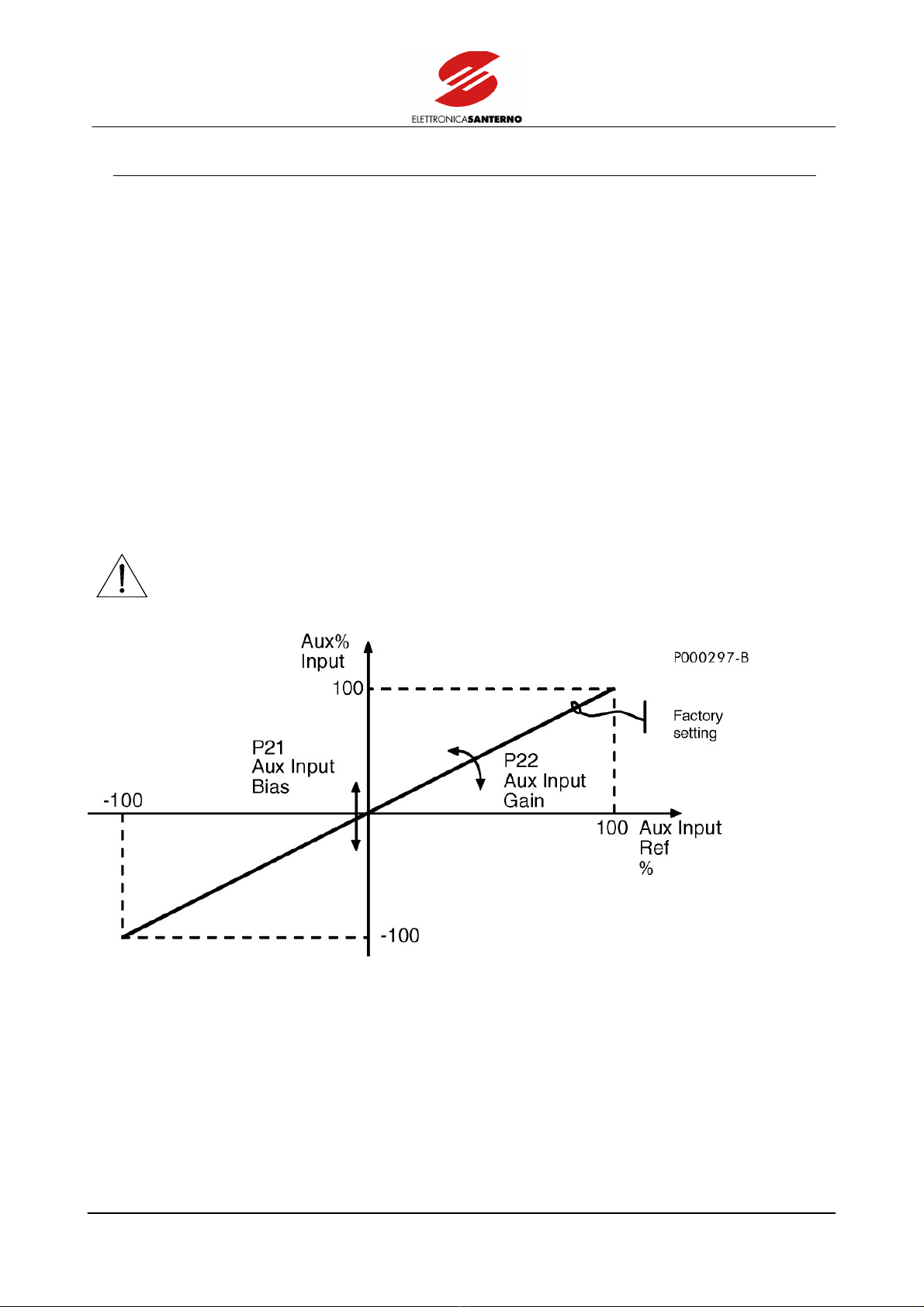
Adjust parameters P21 (Aux Input Bias) and P22 (Aux Input Gain) similarly to inputs relating to terminals 2, 3 and 21.
With reference to Fig. 1.3, the programmable parameters are the following:
P21: Aux Input Bias; value of the signal processed by the inverter (expressed as a value percent) when the signal
applied to terminal 19 is equal to zero.
P22: Aux Input Gain; amplification coefficient (or weakening coefficient) with which the terminal analog signal is
processed.
The processed value is determined by the following formula:
(Aux Input%) = P21 + P22*(Aux Input Ref%)/100
where Aux Input Ref% represents the signal sent to terminal 19 expressed as a percentage with respect to 10V.
CAUTION Never send signals exceeding ±10V to terminal 19.
Figure 3: Parameters relating to auxiliary input processing
PROGRAMMING SINUS K
MANUAL
18/226
1.4. ANALOG OUTPUTS FEATURES
1.4.1. ANALOG OUTPUTS
Two analog outputs are located on terminal 17 and terminal 18. Analog outputs may be used to connect additional
devices or to generate a signal to be sent to other devices. Some particular configuration jumpers located on control
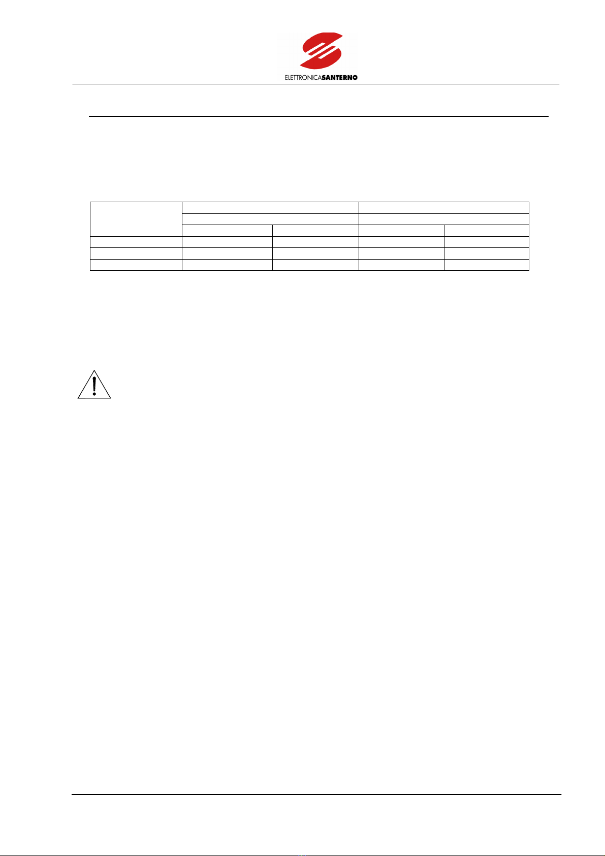
board ES778/2 allow to select the type of output signal (0–10V, 4–20mA or 0–20mA).
Terminal 17 AO1 Terminal 18 AO2
Configuration Jumper Configuration Jumper
Output Type
J7 J5–J8 J4 J3–J6
0–10V pos 2–3 X pos 2–3 X
4–20mA pos 1–2 pos 1–2 pos 1–2 pos 1–2
0–20mA pos 1–2 pos 2–3 pos 1–2 pos 2–3
X=any position
Through the OUTPUT MONITOR menu, set the quantity for the analog output and the ratio between the value of the
output signal and the measured quantity.
The ratio between the output signal and the measured quantity is expressed as the ratio between the quantity value and
the relevant voltage value on the analog output (e.g. Hz/V for IFS SW). When setting the jumpers to configure the
output as 4–20mA or 0–20mA, multiply by 10 the value set to obtain the quantity value when the output delivers 20mA
(e.g.: if P32=10Hz/V, the analog output will deliver 20mA when the inverter delivers 100Hz).
CAUTION Never deliver input voltage to analog outputs. Do not exceed max. allowable current.

SINUS-K PROGRAMMING
MANUAL
19/226
2. MAIN REFERENCE
The main reference is the frequency reference (IFD SW) or the speed/torque reference (VTC SW) acquired when only
the START command is active.
This reference may be sent by two inputs for voltage signals “Vref” (terminals 2 and 3 for signals, terminal 1 for zero
volt), one auxiliary input In aux (terminal 19) and one input “Iref” for a current signal (terminal 21 for the signal,
terminal 22 for zero volt). These inputs are active if parameters C22 (IFD SW) or C14 (VTC SW) are set to Term (factory
setting).
If a signal is sent to more than one analog input, the signal addition is considered as the main reference.
Voltage signal Vref (terminals 2 and 3) may be unipolar (0÷10V, factory setting) or bipolar (±10V) depending on the
position of jumper J14.
Auxiliary power supply (+10V, terminal 4) is available to power an external potentiometer (2.5÷10 kΩ).
Do the following to use a bipolar signal (± 10 V) at the inverter input:
– set jumper J14 to position 1–2 (+/–)
– set parameter P18 (Vref J14 Pos.) as “+/–”
– set parameter P15 (Minimum Ref) as “+/–”
The motor direction of rotation changes when the main reference sign becomes opposite.
Bipolar voltage (±10V) may be sent to input Inaux (terminal 19). The motor direction of rotation changes when
negative signals are sent.
Analog input Iref (terminal 21) acknowledges a current value ranging from 0 to 20mA as an input signal (factory
setting: 4÷20 mA).
If parameters C22 (IFD SW) or C16 (VTC SW) are set to Kpd, the main reference is sent via keypad; signals applied to
terminals 2, 3, and 21 will have no effect.
If parameters C22 (IFD SW) or C16 (VTC SW) are set to REM, the main reference is sent via serial link.
CAUTION Do not apply signals exceeding ±10V to terminals 2 and 3. Do not send current values
higher than 20mA to terminal 21.
NOTE Terminals 2 and 3 and terminal 21 may also be used as inputs for reference and PID
regulator feedback (see section 3.12).
Parameters P16 (Vref Bias), P17 (Vref Gain), P19 (Inmax), and P20 (Iref Gain) allow to change the relationship between
the signals sent to terminals 2, 3, and 21 and the main reference. Two separate settings are possible for voltage inputs
and current inputs. Factory setting corresponds to 0÷10V input signals and to 4÷20mA input signals.
PROGRAMMING SINUS K
MANUAL
20/226
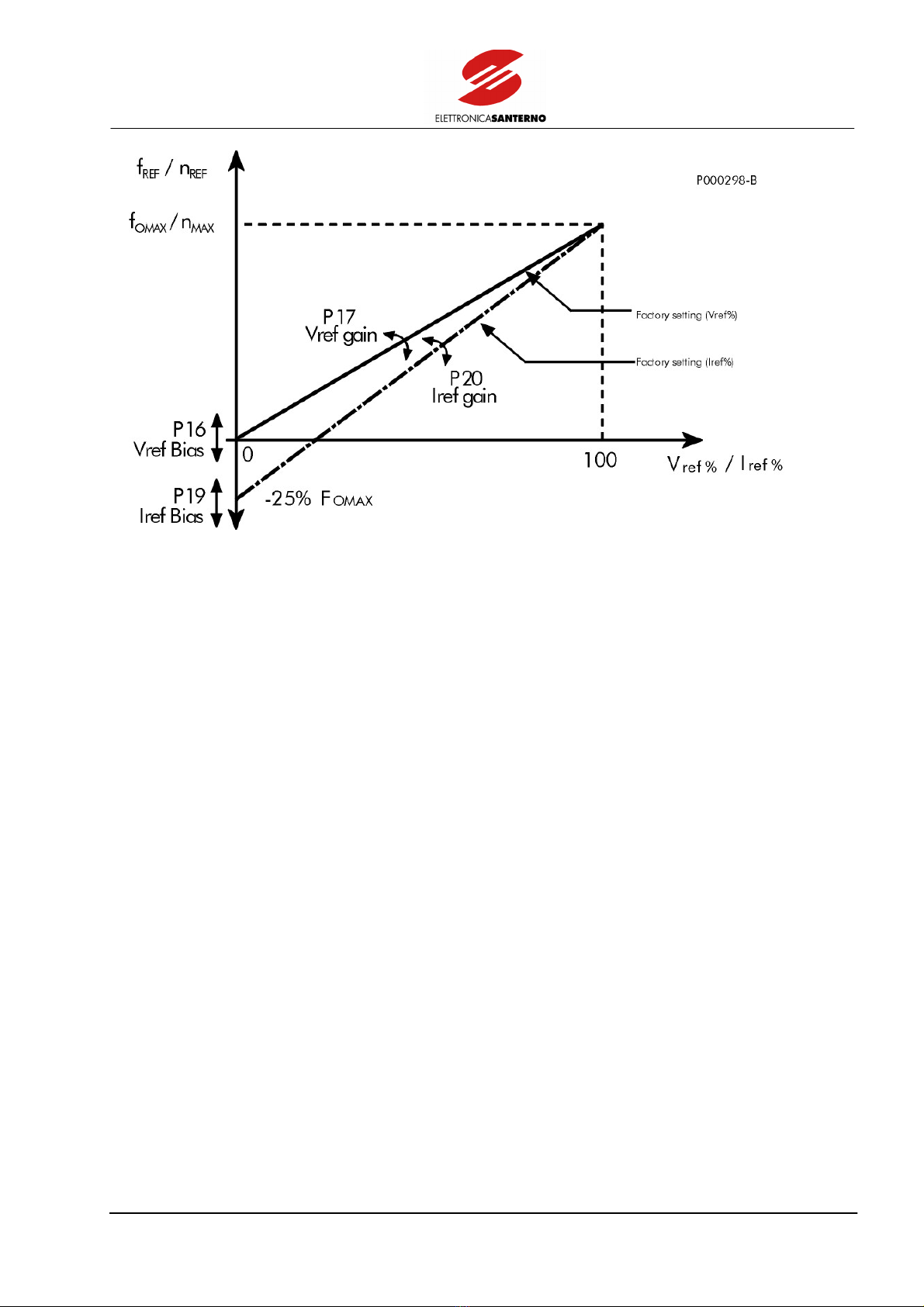
Figure 4: Parameters relating to main reference processing.
With reference to Fig. 4, configurable parameters are the following:
P16 and P19: Vref Bias and Iref Bias; main reference value – expressed as a percentage of the max. output frequency
(IFD SW) or the max. speed of the motor (VTC SW) – produced when all reference signals sent via terminal board
(terminals 2, 3, 21) are set to zero.
P17 and P20: Vref Gain and Iref Gain; amplification coefficient (or weakening coefficient) between the signals sent via
terminal board and the main reference that is obtained.
Example (IFD SW):
Frequency reference Fref expressed in Hz when the first V/f pattern is active (for factory setting, see section 3.1) is
calculated as follows:
Fref = C07/100 * (P16 + Vref%/100 * P17) + C07/100 * (P19 + Iref%/100 * P20)
where:
Vref% is the sum of the signals sent to terminals 2 and 3, expressed as a percentage with respect to 10V; if the signal
addition exceeds 10V, still consider Vref% = 100%.
Iref% is the signal sent to terminal 21 expressed as a percentage with respect to 20mA.
C07 is the max. output frequency of the inverter expressed in Hz and relating to the first voltage/frequency pattern (see
section 6.2).
The first term of the addition is limited from zero to C07 by parameter P18 (Vref J14 Pos) set as +; if P18 is set as +/–,
it is limited to ±C07. The second term of the addition is limited from zero to C07; Fref% between ±C07.
This manual suits for next models
2
Table of contents
Other Elettronica Santerno Inverter manuals

Popular Inverter manuals by other brands


GreenWorks Pro
GreenWorks Pro IV80A00 owner's manual

Fimer
Fimer PVS-166-175-TL-US Quick installation guide

SunSynk
SunSynk Life3.5Hyb02 Installer manual

Powerdiverter
Powerdiverter CTSA16-100A Installation & user guide

Silverline
Silverline 868853 user manual

SolarEdge
SolarEdge StorEdge Solution with Backup installation guide


