Panasonic Urban Multi MX1 Series User manual

PACD011001G2 / PACD011004G3
Urban Multi Inverter “MX1” Series 1
Urban Multi
Inverter “MX1” Series
1. General ...................................................................................................3
1.1 What is “Urban Multi Series”? ..................................................................3
1.2 The Installation is of Vital Importance ......................................................5
2. Points to Bear in Mind at the System Design..........................................6
2.1 Points Relating to the Performance of the Air Conditioning Units............6
2.2 Striking a Balance between System Installation and
General Construction Work (Comprehensive Flow Chart).......................7
2.3 Points to Bear in Mind when Preparing the Contract Drawings ...............8
3. Installation 1..........................................................................................11
3.1 Step by Step Installation Procedure.......................................................11
3.2 Work Involved in Individual Operations
and Points to be Borne in Mind..............................................................12
4. Installation 2..........................................................................................57
4.1 Field Settings..........................................................................................57
4.2 Setting Modes ........................................................................................59
5. Caution for Refrigerant Leaks...............................................................67
5.1 Caution for Refrigerant Leaks ................................................................67
6. Hand Over to Customer........................................................................70
6.1 Operational Steps...................................................................................70
7. Bad Examples and Good Examples in Installation ...............................71
7.1 Example 1: Signal interference due to use of multiple core cable
(all model)...............................................................................................71
7.2 Example 2: Mismatch between cables connecting indoor and
outdoor units and corresponding piping. (all model) ..............................72
7.3 Example 3: Drain pipe trap shape defective...........................................73
7.4 Example 4: Pressure down despite absence of leaks
during air tight test (all model)................................................................74
7.5 Example 5: Excessive noise due to
incorrect angling of Line branch pipes....................................................75
7.6 Example 6: Cracks develop in field pipes due to
thermal expansion and contraction ........................................................76
7.7 Example 7: Transmission wiring between the cool/heat selector and
the outdoor unit is too close to a high voltage wire. ...............................77
7.8 Example 8: The centralized control group number cannot be set
(MX1 Series). .........................................................................................78
7.9 Example 9: “88” cannot be cleared
from the central remote controller. .........................................................79
8. Appendix (Check Points in Installing UM Series)..................................80
8.1 Operating Noise of Indoor Units.............................................................80
8.2 Procedures for Rigging Refrigerant Piping.............................................83
8.3 Piping System Diagrams and Refrigerant Piping Work
for the Inverter MX1 Series ....................................................................87
8.4 Locating Outdoor Units...........................................................................92
8.5 Precaution in Control Wiring Work.........................................................94
PACD011001G2 / PACD011004G3 General
Urban Multi Inverter “MX1” Series 3
1. General
1.1 What is “Urban Multi Series”?
It is an air conditioning system for commercial building application with sophisticated individual zone
control. As you see fromthe figure shown below, it can be used for various applications with a broad range
of flexibility. The major differences between conventional air cooled packaged air conditioners are shown
as follows:
For example : MX1 Series
1. Up to a maximum of 16 indoor units of different capacities and types can be connected to 1 refrigerant
system.
AFTER THE INSTALLATION IS FINISHED, REFRIGERANT PIPING AND ELECTRIC WIRING MUST
BE CHECKED UNIT BY UNIT TO PREVENT WRONG CONNECTION.
2. Up to 100m maximum of actual piping length is possible.
PROPER MEASURES MUST BE TAKEN TO PREVENT TUBES FROM GETTING CONTAMINATED
OR MOISTENED.
WHEN BRAZING, NITROGEN GAS MUST BE PASSED THROUGH TUBES TO PREVENT
OXIDIZATION.
3. Many different control circuits can be selected to meet a wide range of application requirements.
USE PROPER WIRES FOR CONTROL CIRCUIT LINES, BECAUSE THE CONTROL SYSTEM IS
HIGHLY SOPHISTICATED WITH 2 WIRE-MULTIPLEX TRANSMISSION SYSTEM.

General PACD011001G2 / PACD011004G3
4Urban Multi Inverter “MX1” Series
4. Installation job is more complicated
ALL JOBS ON THE SITE SUCH AS INITIAL SETTING OF SWITCHES ETC. MUST BE LISTED UP
AND SCHEDULED IN ADVANCE.
REFRIGERANT TUBE LENGTH TO EACH UNIT AND REFRIGERANT CHARGE AMOUNT MUST BE
ACCURATELY RECORDED FOR THE FUTURE SERVICE.
The “Urban Multi Series” functions properly if the installation is done properly, however, the opposite can
also be true. It must be remembered that the quality of installation is EXTREMELY IMPORTANT!

PACD011001G2 / PACD011004G3 General
Urban Multi Inverter “MX1” Series 5
1.2 The Installation is of Vital Importance
The analysis of major installation problems experienced during the year of 1988 is shown below;
How these installation problems affect an equipment are shown below:

Points to Bear in Mind at the System Design PACD011001G2 / PACD011004G3
6Urban Multi Inverter “MX1” Series
2. Points to Bear in Mind at the System Design
2.1 Points Relating to the Performance of the Air Conditioning Units
A number of points need to be borne in mind at the system design stage in order to ensure the mechanical
efficiency of the air conditioning units.
1. Path of refrigerant piping between outdoor and indoor units, height difference and pipe length.
Path of refrigerant piping should be determined such that lenght of piping is kept to a minimum.
Piping should be kept within permissible limits in terms of length and height difference.
2. Positioning of outdoor unit
Position such that maintenance and repairs can be carried out. (leave room for servicing)
Avoid reduction of airflow and short circuiting
3. Positioning of indoor unit
Position such that maintenance and repairs can be carried out. (inspection port positions and size
check)
Avoid short circuiting
Ensure sufficient drain pipe gradient (need for drain-up kit etc.)
In the case of a ceiling mounted type make sure ceiling depth is sufficient (need for high performance
filter, etc.)

PACD011001G2 / PACD011004G3 Points to Bear in Mind at the System Design
Urban Multi Inverter “MX1” Series 7
2.2 Striking a Balance between System Installation and General Construction
Work (Comprehensive Flow Chart)
Note: 1. The division of the work should be thoroughly clarified. (This applies particularly to work relating to the
connection of control wiring, fitting of remote controller and central control panel, boundary work on
areas such as connection of drain piping and humidification supply piping, inspection and foundation)
2. Keep a constant check on the progress of the construction work to avoid deviations from the air
conditioning work schedule.
3. For sleeve and insert work the positions of ceiling girders should be confirmed and sleeve and insert
requirement, hole diameters, positioning and numbers decided. This is particularly importantin the case
of sleeves for drain piping.

Points to Bear in Mind at the System Design PACD011001G2 / PACD011004G3
8Urban Multi Inverter “MX1” Series
2.3 Points to Bear in Mind when Preparing the Contract Drawings
The following points should be borne in mind when preparing the contract drawings from the original
drawings and the execution drawings.
The contract drawings for the air conditioning system are blueprints for the performance of the necessary
work which are drawn up on the basis of the original drawings in such a way that a working balance is
achieved between the specific requirements of each individual aspect of the work.
Contract Drawing Objectives include:
The drawings should be easily comprehensible to those carrying out the work.
The contents of the drawings should not be subject to subsequent alteration.
The following is a list of the main points to be considered when preparing contract drawigns for the Urban
Multi Series and should be used as a reference during this stage of the work:
2.3.1 At the Contract Drawing Stage the Following Points are Critical!!
Check points
Arrangement of units 1. Have you left the access passages clear and allowed sufficient room for servicing?
2. Have you taken full account of the possibility of short circuits? (Both indoor and outdoor units)
3. Can the air filters be replaced easily?
4. Have you indicated the size and location of the ceiling inspection ports? (Make sure there no other installations in
the area above)
5. Have you taken into account the depth of the installation area? (In case of ceiling built-in type)
6. Have you specified the position of the indoor unit clearly? (Have you taken full accout of relevant features of the
local ventilation, humidity and lighting?)
Refrigerant piping 1. Is the piping system correctly connected?
2. Are the rise and fall pipes correctly connected?
3. Are the lengths and height differences of the pipes within the
recommended limits?
Operational control 1. Are the interconnections between the piping and wiring of the
indoor and outdoor units clearly shown?
2. Are the numbers of the local setting switches clearly shown?
(Group No. and Unit No.)
3. Are thewiringconnectionsbetweenthe remote controllerand the
centralized and remote controls clearly shown?
Refer to the notes relating to the preparation of the control
wiring system diagrams (see next page)
4. Are the different types of wires clearly marked?
5. Are the any problems with the way the power supply cables and
control wiring have been separated or bound together?
6. Are the inter-floor connections of the control wiring correct?
7. Is the position of the remote controller clearly marked?
Miscellaneous 1. Have you checked the gradient of the drain piping? (Must be at
least 1/100)

PACD011001G2 / PACD011004G3 Points to Bear in Mind at the System Design
Urban Multi Inverter “MX1” Series 9
2.3.2 Main Considerations in Preparation of Control Circuit Diagrams
In addition to the design of the appropriate this system configuration it is also essential that the control
stsyem be made amply clear. If the system is designed and installed without a clear, comprehensive plan
then problems are inevitably going to occur during the test run.
Servicing too will become much more time consuming than necessary. However, if control circuit diagrams
are prepared along with the contract drawings in order to make the total system clearly visible then the
essential points relating to the electrical connections will be easily understood, the test run will go off
without a hitch and the whole system will be rendered fully effective.
Step 1: Compiling a
System List
(example using
MX1 Series)
1. Mark each outdoor unit with a code.
2. Add field settings and data for outdoor units, and outdoor unit No. if using sequential start.
3. Add the model number of each indoor unit connected to each refrigerant circuit.
4. Assign each indoor unit a code.
5. Fill in the location of each indoor unit.
6. Group indoor units controlled by one or two remote controllers. (group or individual control).
7. Assign central group Nos. if using centralized control.
8. Add field settings and optional equipment for indoor units.
9. Add unit No. if making separate field settings for each indoor unit under group control.
Note: With the Inverter MX1 Series, unit No. is determined through automatic addressing, therefore readout unit
Nos. after activating the power.
For details on field settings and centralized control group No., refer to the installation manual and system
reference materials.
Example: System list
Outdoor Unit Indoor Unit
ModelName
(code) Field Settings Model Name System Name Location Remote
Controller
Group
Centralized
ControlGroup
No. Unit No. Optional
equipment,field
settings, etc.
CU-10MX
(PAC1)
Cool/Heat
selector:
Indoor unit
Low noise
operation
(L.N.O.P):
Individual control
Sequential start:
ON Defrost:
Earlier
Sequential start
No.
CS-32LM 2F01 2nd floor
office A1–00
CS-63LM 2F02 2nd floor
office A(1–00)
CS-40LM 2F03 2nd floor
office A(1–00)
CS-63LM 2F04 2nd floor
office B1–01
CS-50LM 2F05 2nd floor
office B(1–01)
CU-10MX
(PAC2)
Cool/Heat
selector:
Indoor unit
Low noise
operation
(L.N.O.P):
Individual control
Sequential start:
ON Defrost:
Earlier
CS-32LM 3F01 3rd floor
office C1–02
CS-40LM 3F02 3rd floor
office C(1–02)
CS-50LM 3F03 3nd floor
office C(1–02)
CS-50LM 3F04 3rd floor
office D1–03

Points to Bear in Mind at the System Design PACD011001G2 / PACD011004G3
10 Urban Multi Inverter “MX1” Series
Step 2: Preparation
of the Control
Circuit Diagrams
The following sequence should be followed in order to prepare control circuit diagrams in accordance with
the system list which has already been completed:
1Diagrams should be prepared for each individual outdoor unit. The outdoor unit model number should
be inserted into the diagram. (CU-10MX)
2Insert name of refrigerant system. (PAC1, PAC2)
3Insert name of indoor unit. (CS-32LM→32LM)
4Insert system name of indoor unit.
5Insert installation position. (Do this when demarcation is possible)
6Insert remote controller control wiring. (Group) Indicated by solid line. ........Solid line.
7Insert centralized control wiring. ........Dotted line
8Insert Group No. (GNo. for each indoor unit with UNo. 0)
The control circuit diagrams are now complete.
Example: Control circuit diagram

PACD011001G2 / PACD011004G3 Installation 1
Urban Multi Inverter “MX1” Series 11
3. Installation 1
3.1 Step by Step Installation Procedure
The above list indicates the order in which the individual work operations are normally carried out but this
order may be varied where local conditions warrant such a change.

Installation 1 PACD011001G2 / PACD011004G3
12 Urban Multi Inverter “MX1” Series
3.2 Work Involved in Individual Operations and Points to be Borne in Mind
3.2.1 Sleeve and Insert Work
Operational steps
Positioning of the
Pipe Holes a) The through holes for the drain piping should be positioned such that the pipes have a downward
gradient. (The gradient must be at least 1/100. The thickness of the insulating materials must also be
taken into consideration.)
b) The diameter of the through holes for the refrigerant piping should include an allowance for the
thickness of the heat insulation materials. (It is a good idea to think of the liquid and gas pipes as pairs.)
c) Attention should bepaid to the construction of the beam themselves since there are sometimes parts of
the beam which cannot be used to accommodate through holes.
Example: Through holes in a reinforced concrete beam
Positioning the
Insert a) An insert is a metal tool which is inserted into a floor or a beam before the concrete is set such that
fittings such as ducts, pipes or suspension bolts for hanging units can be fitted into place later. The
positions of the inserts must be decided early.
Example: Steel insert
Important point:
1. The weight of the fitting to be suspended must be taken into account when choosing the insert.
Preliminary talks
with
construction
company
Determine
position, size and
number of units
required
Carry out work Check work
(V0957)

PACD011001G2 / PACD011004G3 Installation 1
Urban Multi Inverter “MX1” Series 13
3.2.2 Installation of Indoor Unit
Operational steps
Positioning 3 essential points when installing an indoor unit
1. Height: Take care to accout for final ceiling facing surface level
2. Level: Level fitting is essential. (within ±1 degree of horizontal)
3. Direction: The unit must be fitted in line with the ultimately visible ceiling joints
Important points
1. The suspension bolts must be strong enough to support the weight of the indoor unit.
2. Optional features must be added to the indoor unit prior to installation.
3. The model name should be checked prior to installation.
4. Take care to align the main unit correctly. (Bearing in mind piping layout and direction of blow out)
5. Leave sufficient space for servicing to be carried out.
6. Make inspection holes for model which need them.
7. Fit the unit to ensure proper drainage.
Example: 2-way cassette type (CS-63LM)
Determine
installation
position Fit indoor unit
Mark installation
position Fit suspension
bolts
(V0960)

Installation 1 PACD011001G2 / PACD011004G3
14 Urban Multi Inverter “MX1” Series
3.2.3 Refrigerant Pipe Work
Operational steps
The 3 Principles of
Refrigerant Piping The “3 principles of refrigerant piping” must be strictly observed
Fit pipes
provisionally
Install indoor unit
Solder Flushing Air tight test Vacuum drying
Cut pipes to size Replace nitrogen
(V0963)
The 3 princples of refrigerant piping
Dry Clean Air tight
Make sure there is no moisture
inside the pipes Make sure there is no dirt inside the
pipe Make sure the refrigerant does not
leak out
Actoin to avoid problemCause of problem
l
Rainwater, work water,
etc. gets into pipes from
outside
l
Moisture generated inside
pipes due to condensation
l
Formation of oxides inside
pipes during soldering
l
Dirt, dust or other
extraneous material gets
into pipes from outside
l
Leak from soldered area
l
Leak from flared area
l
Leak from flange area
Pipe covering Flushing
Replace nitrogen
Pipe covering
Air tight test
Flushing
Vacuum drying
Use the proper materials (copper pipe,
solder, etc.)
Adhere strictly to standard soldering
work practice
Adhere strictly to standard flaring work
practice
Adhere strictly to standard flange
connection work parctice
Clean Dry
Air tight
(V0964)

PACD011001G2 / PACD011004G3 Installation 1
Urban Multi Inverter “MX1” Series 15
Method for
Replacing Nitrogen
(Brazing)
If brazing work is carried out without passing nitrogen gas through the pipes which are being brazed then
this allows the formation of oxidation bubbles on the inside surface of the pipes. These oxidation bubbles
are then carried along inside the pipes to cause damage to various members of the system such as valves
or compressors and the system ceases to function properly.
In order to avoid this problem nitrogen is passed through the pipes while the soldering work is being
carried out. This operation is known as nitrogen replacement. (Air is replaced by nitrogen)
This is standard work practice for all brazing work.
Important points:
1. The gas used must be nitrogen (oxygen, carbon dioxide and refrigerant should not be used.)
2. A pressure regulator must be used.

Installation 1 PACD011001G2 / PACD011004G3
16 Urban Multi Inverter “MX1” Series
Covering of
Refrigerant Pipes Covering is an extremely important operation as it prevents water, dirt or dust from getting inside
the pipes. Moisture inside the pipes was a constant source of trouble in the past. The utmost care is
required to nip this problem in the bud.
The end of each pieces of pipe must be covered. “Pinching” is the most effective method but “taping” is
an simple alternative which may be used according to the work area and term of work.
1. Pinching method
The end of the copper pipe is squeezed together and the gap brazed.
2. Taping method
The end of the copper pipe is covered with PVC tape (vinyl tape).
<Taping method>
Particular care should be taken during the following operations:
When passing copper pipe through a penetration hole (Dirt easily gets into the pipe).
When copper pipe is located outside (Rainwater gets in )
(Special care is needed when the pipes are standing vertically outside)
Location Term of Work Covering Method
Outdoors 1 months or more Pinching
Less than 1 months Pinching or taping
Indoors Irrelevant Pinching or taping

PACD011001G2 / PACD011004G3 Installation 1
Urban Multi Inverter “MX1” Series 17
Refrigerant Pipe
Flushing [3 major effects]
1. Removal of oxidation bubbles formed inside copper pipes when “nitrogen replacement is insufficient”
during soldering work
2. Removal of extraneous material and moisture from pipes when covering has been insufficient
3. Checks connections in pipes linking outdoor and indoor units (Both liquid and gas pipes)
[Example of procedure]
1. Set pressure regulator on nitrogen cylinder.
∗The gas used must be nitrogen.
(There is a danger of condensation if fluon or carbon dioxide are used and oxygen carries the risk of
explosions.)
2. Connect the charge hose from the pressure regulator to the service port on the liquid pipe side of the
outdoor unit.
3. Fit blanking plugs to all indoor units (B) other than unit A.
4. Open the main valve on the nitrogen cylinder and set the pressure regulator to 0.5MPa.
5. Check that the nitrogen is passing through the unit A liquid pipe.
6. Flushing.
Block the end of the pipe with the insulation of your hand.
↓
When the gas pressure becomes too great to contain remove insulation quickly. (First flush)
↓
Block the end of the pipe with insulation again.
↓
(Carry out second flushing)
Flushing is a method of cleaning extraneous matter out of pipes using pressurized gas.

Installation 1 PACD011001G2 / PACD011004G3
18 Urban Multi Inverter “MX1” Series
(The nature and amount of the extraneous material inside the pipe can be checked during flushing by
placing a rag lightly over the end of the pipe. In the unlikely case that even a small quantity of moisture is
found then the inside of the pipe should be dried out thoroughly.)
Action:
1. Flush the inside of the pipe with nitrogen gas. (Until such time as the moisture disappears.)
2. Carry out a thorough vacuum drying operation. (See page 48)
1 Close the main valve on the nitrogen cylinder.
2Repeat the above operation for unit B.
3When the liquid pipe operations have been completed then do the same with the gas pipes.
Choice of Materials
for Refrigerant
Piping
a) Refrigerant piping
The piping used must meet the requirements of the JIS standard or equivalent. (Size, material,
thickness,etc.)
Specification: Oxidized phosphorous seamless copper pipe
Long pipe lengths or coiled pipe (copper pipe with heat insulation coating) should be used to avoid the
necessity for frequent brazing.
The whole job is made easier if rolled copper pipe with a heat insulation coating is used.
Size of Refrigerant Piping
b) Brazed joints and special branches
1. General use (L bend joint, socket joint, T joint, etc.)
Joints must meet the requirements of the relevant JIS standard. (Size, materials, thickness, etc.)
2. Special branches
The line branch pipes or header branch pipes should be used.
Example
Outside Diameter (mm) Wall Thickness (mm)
6.4 0.8
9.5 0.8
12.7 0.8
15.9 1.0
19.1 1.0
22.2 1.2
25.4 1.2
28.6 1.2
31.8 1.2
34.9 1.3

PACD011001G2 / PACD011004G3 Installation 1
Urban Multi Inverter “MX1” Series 19
c) Brazing
The Multi-System requires only copper/copper jointing and the jointing method is explained below.
The use of “hard solder” is essential.
Brazing a) Brazing work should be carried out such that the final result is directed either downwards or sideways.
An upward direction should be avoided wherever possible. (to prevent leakage)
b) Liquid and gas pipe branches should always be dealt with in the specified way with attention being paid
to the direction of the fitting and its angle. (to prevent oil return or drift) For example see page 75.
c) It is standard working practice to use the nitrogen replacement method when brazing.
Important points
1. Every effort must be made to avoid fire. (Clean area where brazing is to be performed and make sure
that fire fighting equipment and water are ready to hand.)
2. Be careful of burns.
3. Make sure that the gap between the pipe and the joint is correct. (To prevent leaks)
4. Is the pipe adequately supported?
As a rule the gaps between supports for horizontal piping (copper pipe) are as follows:
The copper pipe should not be secured directly by metal brackets.
Copper pipe support spacing (From HASS 107-1977)
Nominal diameter 20 or less 25~40 50
Maximum gap (m) 1.0 1.5 2.0

Installation 1 PACD011001G2 / PACD011004G3
20 Urban Multi Inverter “MX1” Series
Flare Connection (a) Stiffened pipe must always be annealed at least once prior to the flaring work.
(b) A pipe cutter must be used to cut the pipe. (Alarge pipe cuttermust be used where the pipe has a large
diameter. When cutting a pipe which is too big for the pipe cutter a metal saw may be used but care
must be taken to ensure that the debris from sawing does not get into the pipe.)
(c) Set the flaring tool to make sure the flare size remains within the prescribed limits.
(d) Coat the inner and outer surface of the flare with refrigerator oil (Ester or ether oil). (this ensures that the
flare nut passes smoothly, preventing the pipe from twisting.)
Do not use SUNISO-4GS oil.
Important points
1. Burrs should be carefully removed.
2. 2 spanners should be used to grip the pipe.
3. The flare nut must be inserted before starting the flaring operation.
4. The appropriate amount of torque should be used to tighten the flare nut.
5. Check that there is no superficial damage to the surface of the flare.
Nominal diameter External diamenter of pipe d Pipe widening dimensions A
3/8B 9.53 12.2~12.8
1/2B 12.7 15.6~16.2
5/8B 15.88 18.8~19.4
3/4B 19.05 23.1~23.7
Standard torques for tightening flare nut ±10%
Size Torque
(kgf-cm) (N-cm)
1/4(6.4φ)144~176 1420~1720
3/8(9.5φ)333~407 3270~3990
1/2(12.7φ)504~616 4950~6030
5/8(15.9φ)630~770 6180~7540
3/4(19.1φ)990~1210 9270~11860
Table of contents
Other Panasonic Inverter manuals

Panasonic
Panasonic VF0 Series 400V class User manual

Panasonic
Panasonic EVERVOLT Smart Box User manual

Panasonic
Panasonic M1S Series User manual

Panasonic
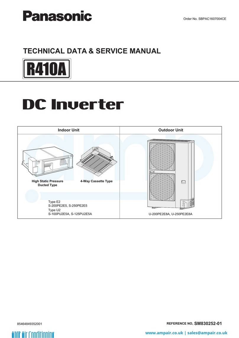
Panasonic U-200PE1E8 Manual

Panasonic
Panasonic EVERVOLT EVHB-I7 User manual

Panasonic
Panasonic S-200PE2E5 Manual

Panasonic
Panasonic S-160PE1R5A Manual

Panasonic
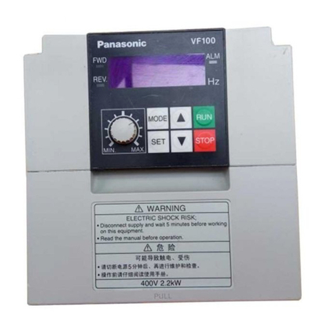
Panasonic VF100 User manual

Panasonic
Panasonic AMK3000P22 User manual

Panasonic
Panasonic S-200PE2E5 Manual