enertik Samil Power SolarLake 10000TL User manual

Distribuidor exclusivo en Argentina
SolarLake PV Grid-tied Inverter
User Manual

02
Contents
1 NOTES ON THIS MANUAL................................................................................................05
1.1 SCOPE OF VALIDITY..................................................................................................................................05
1.2 TARGET GROUP.........................................................................................................................................05
1.3 SYMBOLS USED.........................................................................................................................................05
2 SAFETY..............................................................................................................................07
2.1 APPROPRIATE USAGE..............................................................................................................................07
2.2 IMPORTANT SAFETY INSTRUCTIONS.....................................................................................................07
2.3 EXPLANATION OF SYMBOLS....................................................................................................................08
3 INTRODUCTION.................................................................. ...............................................10
3.1 BASIC FEATURES.......................................................................................................................................10
3.2 ELECTRICAL BLOCK DIAGRAM.................................................................................................................10
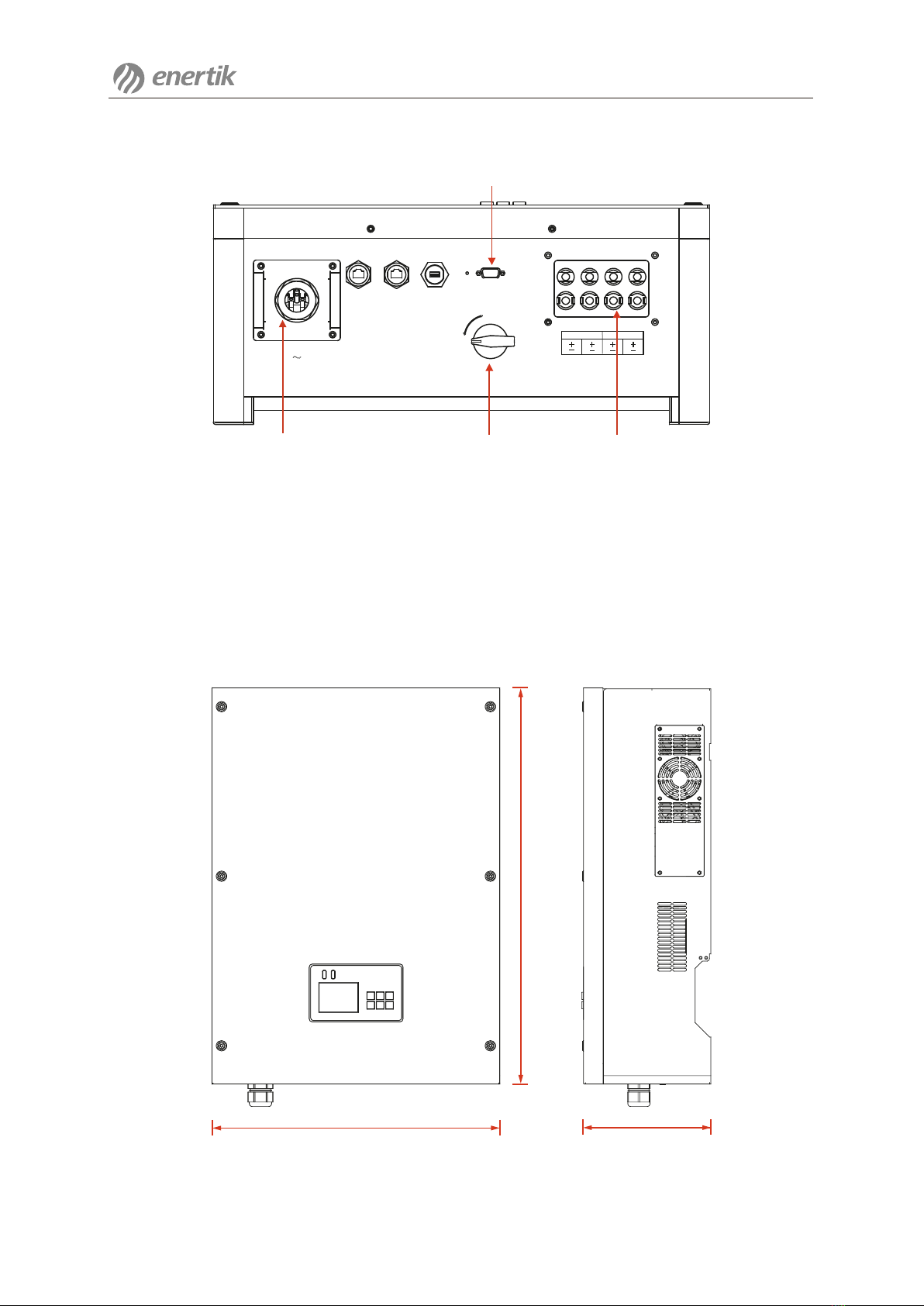
3.3 DIMENSION................................................................................................ .................. ...............................11
4 TECHNICAL DATA.............................................................................................................12
4.1 INPUT (DC)...................................................................................................................................................12
4.2 OUTPUT (AC)...............................................................................................................................................12
4.3 EFFICIENCY, SAFETY AND PROTECTION................................................................................................13
4.4 GENERAL DATA..........................................................................................................................................13
5 INSTALLATION............................................................................................................................................14
5.1 PACKAGING.................................................................................................................................................14
5.2 INSTALLATION PRECAUTION....................................................................................................................15
5.3 PREPARATION............................................................................................................................................16
5.4 INSTALLATION STEPS................................................................................................................................16
5.5 CONNECTIONS OF THE PV POWER SYSTEM.........................................................................................17
5.6 RUN THE INVERTER...................................................................................................................................21
6 OPERATION METHOD...............................................................................................................................22
6.1 CONTROL PANEL........................................................................................................................................22
6.1.1 LCD COMMISSIONING SETUP OPERATION STEPS.............................................................................24
6.1.2 MAIN MENU INTRODUCTION..................................................................................................................27
6.1.3 AUTOTEST PROCEDURE- ITALY ONLY................................................................................................28
6.2 LCD FUNCTION......................................................................... ..................................................................29

03
7. COMMUNICATION AND MONITORING..............................................................................................34
7.1 COMMUNICATION INTERFACE..................................................................................................................34
7.2 COMMUNICATION........................................................................................................................................34
8 TROUBLESHOOTING.................................................................................................................................35
8.1 TROUBLESHOOTING...................................................................................................................................35
8.2 ROUTINE MAINTENANCE............................................................................. ..............................................38
9 DECOMMISSIONING..................................................................................................................................39
9.1 DISMANTLING THE INVERTER..................................................................................................................39
9.2 PACKAGING.................................................................................................................................................39
9.3 STORAGE.....................................................................................................................................................39
9.4 DISPOSAL....................................................................................................................................................39
10 CONTACT SAMIL POWER.....................................................................................................................40

04
1 Notes on This Manual
This manual is an integral part of the inverter, Please read the product manual carefully before
installation, operation or maintenance. Keep this product manual for future reference. Please
note that all pictures are edited by Samil Power.
1.1 Scope of Validity
This product manual describes the assembly, installation, commissioning, maintenance and
failure search of the following Samil Power SolarLake Series inverters.
SolarLake 10000TL SolarLake 12000TL
SolarLake 15000TL SolarLake 17000TL
Keep this manual where it will be accessible at all times.
Product label
The product label provides basic information of the inverter,which is attached to the right side
of the inverter. Pay special attention to the type of inverter and other specifications.
Figure 1 Labels for SolarLake 10000TL, SolarLake 12000TL, SolarLake 15000TL
and SolarLake 17000TL (From left to right)
1.2 Target Group
This manual is for qualified person (support person, service person are qualified mentioned in
this manual). The tasks described in this manual must only be performed by qualified person.
1.3 Symbols Used
The following types of safety instructions and general information appear in this document as
described below.
Notes on This Manual

05
Danger!
Danger indicates a hazardous situation which, if not avoided, will result
in death or serious injury.
Warning!
Warning indicates a hazardous situation which, if not avoided, could
result in death or serious injury.
Caution!
Caution indicates a hazardous situation which, if not avoided, could
result in minor or moderate injury.
Note!
Note provides tips that are valuable for the optimal operation of user
product.
Notes on This Manual

06
2 Safety
2.1 Appropriate Usage
The SolarLake Series is a PV inverter which converts the DC current of a PV generator into
AC current and feeds it into the public grid.
Figure 2 PV Grid-connected System
PV Modules Grid-connected Inverter Grid
2.2 Important Safety Instruction
Danger!
Danger to life due to high voltages in the inverter!
•All work on the inverter must be carried out by qualified personnel only.
•The appliance is not to be used by children or persons with reduced
physical sensory or mental capabilities, or lack of experience and
knowledge, unless they have been given supervision or instruction.
•Children should besupervised to ensure that they do not play with
the appliance.
Caution!
Danger ofburn injuries due to hot enclosure parts!
During operation, the upper lid of the enclosure and the enclosure body
may become hot.
Caution!
Possible damage to health as a result of the effects of radiation!
•Do not stay closer than 20 cm tothe inverter for any length of time.
Safety

07
Warning!
Ensure input DC voltage ≤ Max. input DC voltage .Over voltage may cause
permanent damage to inverter or other losses, which will not be included
in warranty! This chapter contains important safety and operating
instructions. Read and keep this Operation Guide for future reference.
Note!
Grounding the PV generator. Comply with the local requirements for
grounding the PV modules and the PV generator. Samil Power recommends
connecting the generator frame and other electrically conductive surfaces
in a manner which ensures continuous conduction and ground these in
order to have optimal protection of the system and personnel.
2.3 Explanation of Symbols
This section gives an explanation of all the symbols shown on the inverter and on the type label.
●Symbols on the Inverter
Symbol Explanation
5min
Danger to life due to high voltages in the inverter!
There is residual voltage in the inverter. The inverter requires
5 minutes to discharge.
•Wait 5 minutes before user open the upper lid or the DC lid.
● Symbols on the Type Label
Symbol Explanation
CE mark.
The inverter complies with the requirements of the applicable
CE guidelines.
● Important Safety Instructions
When using the product, please do remember the below information to avoid the fire, lightning or
other personal injury:
Safety

08
Warning!
Authorized service personnel must disconnect both AC and DC power from
the SolarLake Series inverter before attempting any maintenance or cleaning
or working on any circuits connected tothe SolarLake Series inverter.
● Before using the SolarLake Series inverter, read all instructions and cautionary markings on
the SolarLake Series inverter, and all appropriate sections of this guide.
● Use only attachments recommended or sold by Samil Power. Doing otherwise may result in
a risk of fire, electric shock, or injury to persons.
● To avoid a risk of fire and electric shock, make sure that existing wiring is in good condition
and that wire is not undersized. Do not operate the SolarLake Series inverter with damaged or
substandard wiring.
●Do not disassemble the SolarLake Series inverter. It contains no user-serviceable parts. See
Warranty for instructions on obtaining service. Attempting toservice the SolarLake Series
inverter user self may result in a risk of electric shock or fire and will void user warranty.
● To reduce the risk of electric shock, authorized service personnel must disconnect both AC
and DC power from the SolarLake Series inverter before attempting any maintenance or cleaning
or working on any circuits connected to the SolarLake Series inverter. Turning off controls will
not reduce this risk.
● Keep away from flammable, explosive materials to avoid fire disaster.
● The installation place should be away from humid or corrosive substance.
● To avoid electric shock accident, please do not disassemble the inverter because there are
high-voltage capacitances installed inside the inverter. Fatal High-voltage will remain in the inverter
after its disconnection with grid after 5 minutes.
● To reduce the chance of short-circuits, authorized service personnel must use insulated
tools when installing or working with this equipment.
Safety

09
3 Introduction
3.1 Basic Features
Congratulations on user purchase of aSolarLake Series inverter from Samil Power. The SolarLake
Series inverter is one of the finest inverter on the market today, incorporating state-of-the-art
technology, high reliability, and convenient control features.
● Advanced DSP control technology.
● Utilize the latest high-efficiency power component.
● Optimal MPPT technology.
● 2 independent MPP trackers.
● Advanced anti-islanding solutions.
● Max. efficiency up to 98%, EU efficiency up to 97.6%.
● THD<3%.
● Power factor adjustable arrange:+/-0.9.
● DC switch (optional).
● Grounding facility.
● Safety & Reliability: Transformerless design with software and hardware protection.
● IP65 protection.
● Friendly HMI.
● LED status indications.
● Multi language LCD display, Human-Machine interaction through button.
● RS485/RS232, Ethernet(USB and CAN is optional) communication interface.
● PC remote control.
3.2 Electrical Block Diagram
● Electrical block diagram
Figure 3 Electrical block diagram(DC switch is optional)
Communication Interface LCD
Control Board
Input
Board
Inverter
Board
Boost
Board
Output
Board
Output to grid
Solar input
Introduction

10
●Terminals of PV inverter
COM1
1 2
AC GRID
AC Output DC Switch
RS232
DC Input
COM2 USB RS-232
ON
OFF
Figure 4 Terminals of PV inverter for 10 KW~17 KW(DC switch is optional)
Note: For safety reasons, the use of a DC switch is recommended. Between the PV modules
and the power modules may be mandatory in some countries. Customers can select Samil
Power SolarLake series inverters according to application requirements.
3.3 Dimension
●Dimension for SolarLake 10000TL, SolarLake 12000TL, SolarLake 15000TL and SolarLake
17000TL
Figure 5 Overview of the inverters dimension
714mm
520mm 230mm
Introduction

11
Note: The AC output terminal is most length part at the bottom of inverter, so take care of the
AC output terminals, do not make it stand on the ground or other materials while moving or
lifting the inverters, otherwise will make terminal damaged.
4 Technical Data
4.1 Input (DC)
Model
Max. recommended DC
power [W]
Max.DC voltage [V]
Total max. input Current
[A]
Number of MPP trackers
/ strings per MPP tracker
MPPT voltage range (at
full power) [V]
Min. DC voltage /start
voltage [V]
10400 12500 15600 17600
1000 1000 1000 1000
A:16/B:16 A:16/B:16 A:20/B:20 A:20/B:20
2/2 2/2 2/2 2/2
320~800 380~800 380~800 430~800
200/250 200/250 200/250 200/250
4.2 Output (AC)
10000 12000 15000 17000
10000 12000 15000 17000
3/N/PE,
230/400
3/N/PE,
230/400
Model
AC nominal power [W]
Max. AC power [W]
16 19.2 24 25
Max. AC current [A]
Nominal AC voltage [V]
Power factor(cos)
Total harmonic distortion
(THD)
3/N/PE,
230/400
3/N/PE,
230/400
AC grid freq. [Hz] 50 50 50 50
0.9leading…….
0.9lagging
0.9leading…….
0.9lagging
0.9leading…….
0.9lagging
0.9leading…….
0.9lagging
<3% <3% <3% <3%
Introduction &Technical Data
SolarLake
10000TL
SolarLake
12000TL
SolarLake
15000TL
SolarLake
17000TL
SolarLake
10000TL
SolarLake
12000TL
SolarLake
15000TL
SolarLake
17000TL

12
4.3 Efficiency, Safety and Protection
Model
Max. efficiency
Euro-efficiency
MPPT efficiency
Overvoltage / Undervoltage
protection
DC isolation impedance
monitoring
Ground fault protection
Grid monitoring
Ground fault current
monitoring
DC injection monitoring
98.0%
97.6%
99.9% 99.9% 99.9% 99.9%
97.6% 97.6% 97.6%
98.0% 98.0% 98.0%
Yes Yes Yes Yes
Yes Yes Yes Yes
Yes Yes Yes Yes
Yes Yes Yes Yes
Yes Yes Yes Yes
Yes Yes Yes Yes
4.4 General Data
Model
Dimension (W/H/D) [mm]
Weight [kg]
Cooling concept
Noise emission (typical)
[dB]
Operating temperature
range [°C]
520*714*230 520*714*230 520*714*230 520*714*230
49 49 50 50
Fan
<45.8 <45.8 <45.8 <45.8
-20 °C ~+60°C (Derating at 45 °C)
Technical Data
SolarLake
10000TL
SolarLake
12000TL
SolarLake
15000TL
SolarLake
17000TL
SolarLake
10000TL
SolarLake
12000TL
SolarLake
15000TL
SolarLake
17000TL

13
Degree of protection
Pollution Degree
Topology
Internal consumption
( night ) [W]
LCD display
Communication
interfaces
Standard warranty(Year)
IP65
II
Transformerless
<5 <5 <5 <5
3.5Inch,
TFT-LCD
3.5Inch,
TFT-LCD
3.5Inch,
TFT-LCD
3.5Inch,
TFT-LCD
RS485/RS232 /
Ethernet;
USB and CAN
Optional
RS485/RS232 /
Ethernet;
USB and CAN
Optional
RS485/RS232 /
Ethernet;
USB and CAN
Optional
RS485/RS232 /
Ethernet;
USB and CAN
Optional
5555
5 Installation
5.1 Packaging list
Please Check the package list, find out all these in the package. The product on the list are for
installation. If find some damage or missing, please contact Samil Power’s sales. Please see
table 1.
Description
SolarLake inverter
Bracket
Screw package
RJ45
Input DC connector
Product manual
Warranty card
Packing list
Quality certificate
QTY Remark
1
1
1
2
8
1
1
1
1
Screw package: 2M4screws, 5ø6screws,
5 expansion screws
Table 1 Packing list
Technical Data&Installation

14
Warning!
Before installation and maintenance,AC and DC side doesn’t carry
electricity, but if DC side is just disconnected, capacitance still contains
electricity, so please wait for at least 5 minutes to ensure the capacitors
completely release the energy and inverter is not electrified.
Note!
Inverters must be installed by qualified person.
SamilPower assures the product guarantee of the SolarLake series inverters during five years
after your purchase, if the installation site does not meet the instructions described in this manual,
it is out of warranty. The warranty is limited tothe costs of repair and/or replacement of the
product by Samil Power only.
Ventilation is very important to cool the inverter, For outdoors application, the inverter requires at
least 50 cm (see table 2) of clearance among the other units and ground. it is recommended
that the same clearance(50cm).
Position Min. Size
Side
Top
Bottom
Front 50cm
50cm
50cm
50cm
50cm
50cm
50cm
50cm
50cm
Figure 6 Space specification Table 2 Available space size
Installation
5.2 Installation precaution

15
5.3 Preparation
Below tools are needed before installation.
Figure 7 Installation tools
Installation Tools: crimping pliers for binding post and RJ45, screw drivers and manual wrench
and ø 8 driller, rubber hammer.
5.4 Installation Steps
Step1: Drill holes in the wall with ø 8 driller according to the size of bracket. Keep drilling vertical
to the wall, and don’t shake when drilling to avoid damage to the wall. It need repositioning
and drilling holes if the hole with much error. Then put expansion pipe into the hole vertically,
use rubber hammertotap the pipe into the wall completely. After that, 5 screws should be twisted
into pipes with bracket. See step 1.
Step 1 Step 2
Installation

16
Step 3 Step 4
Figure 8 Bracket installation
Step2: Use the bracket to install the inverter onto the narrow vertical panel (or wall). make
upper corner part of inverter hanging onto the bracket, lower part match the standard of the
bracket.See step 2.
Step3: Make sure the bracket and the inverter side screw holes in a line and matching
well, put the screw(there are left and right 2 screws ) into the hole and drive into the
inverter tightly. See step 3.
Step4: Lock the inverter and the bracket with lock for safety consideration. (This is
optional for users. User can select the lock according toyour requirements).See step 4.
5.5 Connections of the PV power system
●PV String input connection
SolarLake series inverters (SolarLake 10000TL, SolarLake 12000TL, SolarLake 15000TL
and SolarLake 17000TL) can be connected to2PV string groups, each group can divided
into 2-strings PV modules. Please select PV modules with excellent function and reliable
quality. Open-circuit voltage of module arrays connected in series should be <Max. Input
DC (Table 3) input voltage; operating voltageshould be conformed to MPPT voltage range.
Model
Max. Input DC voltage 1000 V
Table 3 Max. DC Voltage Limitation
Installation
SolarLake
10000TL
SolarLake
12000TL
SolarLake
15000TL
SolarLake
17000TL

17
Please use PV cable to connect modules to inverter. From junction box(Must have fuse
spec.:1000V, 25A fast action) to inverter, voltage drop is about 1-2%. So we suggest
the inverter install near PV module, in order to save cable and reduce DC loss.
Note!
Please don’t connect the PV panel positive or negative to ground.
And do not apply for thin film panel.
Figure 9 Use multimeter to measure module array voltage and detect the polarity
Note :Check the PV+ and PV- from the PV string combiner box correctly, Make sure the PV+
and PV- are connected correctly.
Warning!
PV module voltage is very high which belongs to dangerous voltage
range, please comply with electric safety rules when connecting.
Warning!
When there is something wrong with module arrays, modules can be
connected with PV grid-tied inverter only after eliminating these problems.
Installation

18
Please use PV cable to connect modules to inverter. From junction box(Must have fuse
spec.:1000V, 25A fast action) to inverter, voltage drop is about 1-2%. So we suggest
the inverter install near PV module, in order to save cable and reduce DC loss.
Note!
Please don’t connect the PV panel positive or negative to ground.
And do not apply for thin film panel.
Figure 9 Use multimeter to measure module array voltage and detect the polarity
Note :Check the PV+ and PV- from the PV string combiner box correctly, Make sure the PV+
and PV- are connected correctly.
Warning!
PV module voltage is very high which belongs to dangerous voltage
range, please comply with electric safety rules when connecting.
Warning!
When there is something wrong with module arrays, modules can be
connected with PV grid-tied inverter only after eliminating these problems.
Installation

19
PE
N
L3 L2 L1
10mm
Figure 11 AC output area with terminal block for 5 wires of cable
Below is the AC cable specification table when select the cable for installation.
Model
Cable (Cu)
Micro-Breaker 25A 25A 32A 32A
≥4mm 2≥4mm 2≥6mm 2≥6mm 2
Table 4 Cable and Micro-breaker Requirement
Note:For safety reasons,make sure you select the correct specification cables for installation,
otherwise the power will make the cable hot and overload, it could result in death or serious injury.
Below are the steps for AC output wiring.
Step1: Get out of the four screws at four corners of the cover, get off the cover.
Step2: There are 5 white terminals, which are PE, N, L3(T), L2(S), L1(R). Put the 5 wire of AC cable
through the house tunnel, then put the wire into the terminals correctly(make sure the phase
sequence is correctly connected).
Step3: After 5 wires are connected with terminals please check the wire is in right location.
(L wire is connected with L terminal)
Step4: Put the terminal house on the terminals, get four screws on.
RCMU breaker should be installed between inverter and grid, and its rated fault current:
100 mA≤Ifn≤300 mA,0.1S,Any load should not be connected with inverter directly.
Installation
SolarLake
10000TL
SolarLake
12000TL
SolarLake
15000TL
SolarLake
17000TL

20
Figure12 Incorrect Connections between Load and Inverter
Impedance of SolarLake inverter AC connecting dot should be less than 2 Ω. To ensure reliable
anti-islanding function , PV cable should be used to ensure wire loss <1% than normal power.
Moreover, length between AC side and grid connecting dot should be less than 150m. Below
chart is cable length, section area and wire loss.
Figure 13 AC Cable Loss
5.6 Run the inverter
Start inverter after checking all below steps
a. Make sure all the DC Switch and AC breaker are disconnect.
b. AC cable is connected to grid correctly.
c. All PV modules are connected to inverter correctly,DC connectors which are not used should be
sealed by cover.
Installation
OK
Esc
Input
Output
0
0
0.5
1
1.5
2
2.5
3
10 20 30 40 50 60 70 80 90 100
Length(m)
Loss(%)
4mm²
6mm²
8mm²
10mm²
This manual suits for next models
3
Table of contents
Other enertik Inverter manuals
Popular Inverter manuals by other brands

Hoymiles
Hoymiles HMS-1500-4T Quick installation guide

Veichi
Veichi SI30 series manual

NPower
NPower 457300 owner's manual

Mitsubishi Electric
Mitsubishi Electric 800 Series Instruction Manual (Function

Wagan
Wagan 400W user manual

Southwest Windpower
Southwest Windpower 30 FOOT (9 Meter) TOWER KIT for WHISPER 500 owner's manual

Daikin
Daikin H-Series Service manual

RBI
RBI UL 2703 installation guide

SolaX Power
SolaX Power X3-Hybrid Series user manual

Valen
Valen SRA V30 Operation manual

Jiangsu GoodWe Power Supply Technologu Co.
Jiangsu GoodWe Power Supply Technologu Co. SS series user manual

Goodwe
Goodwe GW9900-MS-30 Quick installation guide