ELEVATE OUTDOOR Stabilizer-Jack-HC-2 Parts list manual
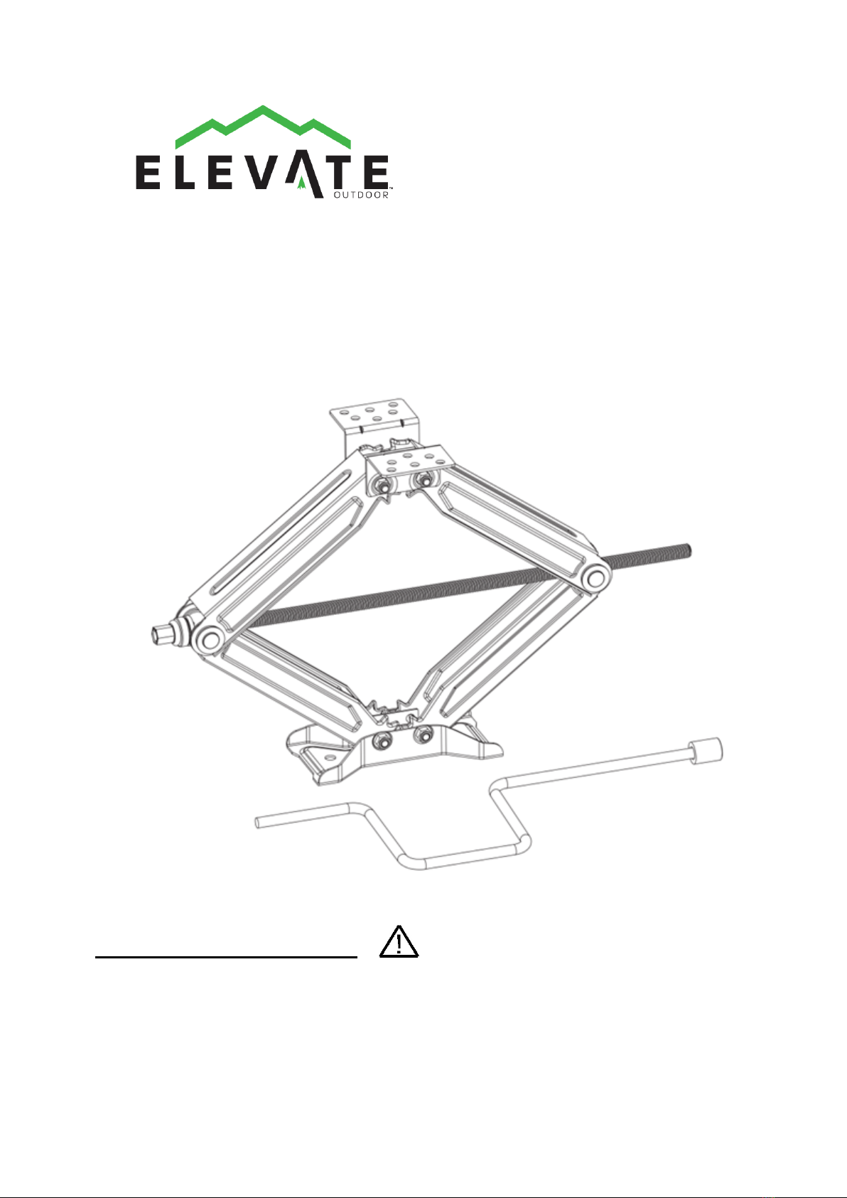
Instructions for
Part # Stabilizer-Jack-HC-2
General Guidelines
Read carefully and understand all ASSEMBLY AND OPERATION INSTRUCTIONS
before operating. Failure to follow the safety rules and other basic safety precautions
may result in serious personal injury.
Rev. 210617 1-888-651-3431
Page1

2
INTENDED USE
• Stabilizer jack are designed for leveling and stabilizing recreational vehicles, campers
and trailers.
• Anything that extends beyond the lines is at risk of damage or destruction from off-road
driving, entering or exiting driveways, or uneven terrain.
• DO NOT use this jack to lift tires off ground or lift excessive weight, it may cause damage
of vehicle frame and door jam.
• DO NOT raise the corner or extreme ends of trailer to excessive height, it may cause the
damage of trailer.
• DO NOT use this stabilizer jack to change tires. DO NOT use cheater bar or impact
wrench.
• DO NOT exceed rated capacity.
• DO NOT apply a load to this jack below 13-3/4" in height.
• Keep out from under trailer/RV, keep hands away from scissor mechanism, keep children
away.
• Always use on hard and flat surface, always block the wheels.
• Failure to follow instructions may result personal injury and/or property damages.
• Some RV sub-frame are not capable to handling extra forces beyond it intended design
strength to support cabin weight. Contact your RV manufacturer about the sub frame
strength information before installing these stabilizer jacks.
TECHNICAL SPECIFICATIONS
Property
Specification
Item#
2130
Ext Height
24''
Lift Capacity (lbs.)
5,000
Rev. 210617 1-888-651-3431 Page2

3
GENERAL SAFETY RULES
WARNING: Read and understand all instructions. Failure to follow all instructions listed
below may result in serious injury.
CAUTION: Do not allow persons to operate or assemble this electric jack until they
have read this manual and have developed a thorough understanding of how the jack works.
WARNING: The warnings, cautions, and instructions discussed in this instruction
manual cannot cover all possible conditions or situations that could occur. It must be
understood by the operator that common sense and caution are factors which cannot be built into
this product, but must be supplied by the operator.
SAVE THESE INSTRUCTIONS
IMPORTANT SAFETY CONSIDERATIONS
JACK USE AND CARE
• Do not modify the jack in any way. Unauthorized modification may impair the function and/or
safety and could affect the life of the equipment. There are specific applications for which the
jack was designed.
Rev. 210617 1-888-651-3431 Page3
Tools and Components Required
l C-clamps
l 50’string
l Electric drill
l 1/8" drill bit
l 11/32" drill bit Arc welder(Used only if welding jacks to frame)
l 9/16” socket
l Appropriate hardware (Required if not welding)
l Ratchet w/extension
l Lithium grease
l Appropriate safety protection (gloves, eye protection, etc.)

4
• Always check for damaged or worn out parts before using the jack. Broken parts will affect
the jack operation. Replace or repair damaged or worn parts immediately.
• Do not force the jack. Do not attempt to lift more than the maximum lifting capacity of 5000-lb.
Where to Find the Correct Location for Installation
For recreational trailer or 5th wheel
:
Step 1a:
Park on level ground. Chock the tires and check the ground clearance.
Step 2a:
From the front corner of the trailer frame, draw a string to the bottom of the front tire. Repeat the
procedure from the rear trailer frame to the bottom of the rear tire as seen in the illustration.
Note:
Anything that extends beyond the lines is at risk of damage or destruction from off-road driving,
entering or exiting driveways, or uneven terrain.
For RV/Motorhome:
Step 1b:
Park the RV on level ground and apply the emergency brake. Check for suitable ground clearance
and chock all of the vehicle's tires.
Step 2b:
From the front bumper to the bottom of the front tire, draw a string. Repeat the process drawing a
string from the overhang, or rear bumper to the bottom of the rear tire.
Note:
Any objects that extend past the lines is at risk for damage, destruction, or falling off due to uneven
ground conditions, entering or leaving driveways, or excursions off-road.
When Finding Your Vehicle’s Mounting Placement, check:
1.Ground clearance suitability
2.Jack handle receivers are accessibly placed
3.There is sufficient clearance for other under-frame components
Rev. 210617 1-888-651-3431 Page4
5
Installation
Step 3:
For any compatible vehicle, either in the front or the rear of the vehicle, place the jack closest to
the frame. Make sure to stay within the previously placed string's perimeter. Hold the completely
collapsed jack in place with C-clamps or Vice Grips. The handle receivers are to be placed
outward, but must not extend past the trailer.
• Check the placement by opening and closing the jack handle. This ensures there is
ample space for movement, without obstruction from the vehicle's chassis or under frame
components, such as exhaust pipe, etc.
• If necessary, move the scissor jack to find an unimpeded placement.
Step 4:
Once an acceptable position for all of the jacks is found, open the jacks until they touch the
ground. It is important to use enough pressure to ensure the jacks do not move during the final
installation processes.
Caution:During either bolt or welding installation, make sure drilling or welding will not damage
any components under the chassis: fuel or brake lines, water, gas, electrical, or generator
fuelines, water heater, holding tank plumbing.
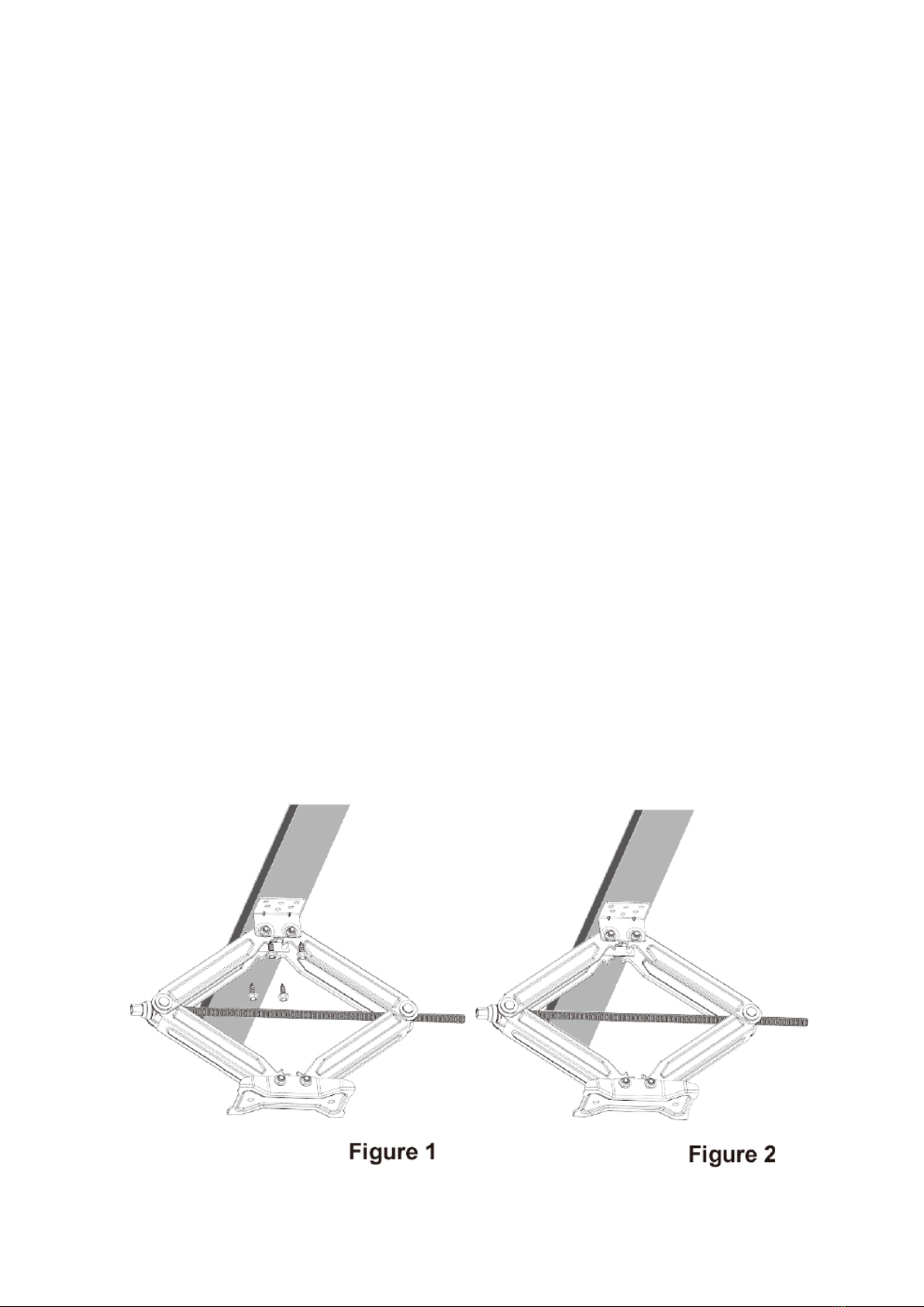
Step 5: For Bolting Installation
Once the scissor jack placement is located, use the mounting plate as a template, and on the
vehicle frame, mark the location of the holes. Remove the jack.
• Use a hammer and center punch to mark the placement of the center of each hole.
• Use 1/8" bit to create pilot holes and an 11/32" drill bit to finish drilling the holes.
• Replace the jack, use a 9/16" socket and ratchet, attach the scissor jacks to the frame
using 4 self tapping 3/8"x1" screws (Figure 1).
• Use lithium grease to lubricate the scissor jack leveler screw. This step should be repeated
yearly.
Rev. 210617 1-888-651-3431 Page5
Table of contents
Popular Jack manuals by other brands

Pittsburgh
Pittsburgh 62590 Owner's manual & safety instructions

Powerbuilt
Powerbuilt 640405 Operating and maintenance instruction manual

Clarke
Clarke STRONG-ARM CTJ3000G quick start guide

Clarke
Clarke CTJ2500QLG Operating & maintenance instructions

Omega Lift Equipment
Omega Lift Equipment 18122C Operating instructions & parts manual

Pittsburgh
Pittsburgh 58816 Owner's manual & safety instructions


