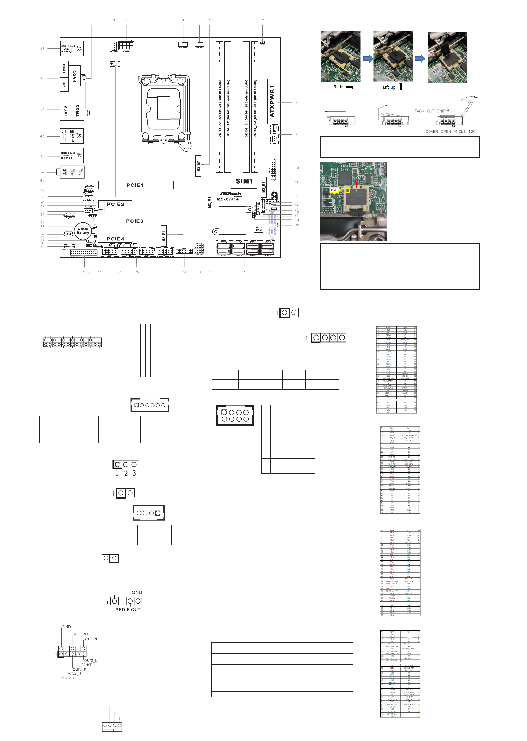
manuals.online logo
Brands
  1. Home
  2. •
  3. Brands
  4. •
  5. ASRock Industrial
  6. •
  7. Motherboard
  8. •
  9. ASRock Industrial IMB-X1314 Service manual

ASRock Industrial IMB-X1314 Service manual

14 : Panel Power Select (PNL_PWR1)
1-2 : +3V
2-3 : +5V
4-5 : +12V
15 :
CON_LBKLT_EN and CON_LBKLT_CTL
Voltage Level (BLT_EN_PWM1)
1-2 : 5V Level
2-3 : 3V Level
16 : Inverter Power Control Wafer (BLT_PWR1)
Chassis Intrusion Headers (CI1, CI2)
17 : CI1 :
Short : Active Case Open
Open : Normal
31 : Cl2 :
Short : Normal
Open : Active Case Open
18 : Backlight & Amp Volume Control
(BLT_VOL1)
19 : Backlight Power Select
(LCD_BLT_VCC) (BKT_PWR2)
1-2 : LCD_BLT_VCC : +5V
2-3 : LCD_BLT_VCC : +12V
20 : LVDS Panel Connector
COM Port Pin9 PWR Setting Jumpers
1 : PWR_COM1 (For COM Port1)
PWR_COM2 (For COM Port2)
26 : PWR_COM3 (For COM Port3)
PWR_COM4 (For COM Port4)
PWR_COM5 (For COM Port5)
PWR_COM6 (For COM Port6)
1-2 : +5V
2-3 : +12V
2 :
4-Pin Chassis FAN Connector
(+12V) (CHA_FAN1)
3 :
ATX 12V Power Connector
4 :
4-Pin Chassis FAN Connector
(+12V) (CHA_FAN3)
5 :
4-Pin CPU FAN Connector
(+12V) (CPU_FAN1)
7 : Power Loss Header (PWR_LOSS1)
Short : Power Loss
Open : No Power Loss
8 :
24-pin ATX Power Input Connector
9 : Thunderbolt AIC Connectors (TB1, TB2)
10
: USB 3.2 Gen1 Header
(
USB3_5_6
)
12 :
System Panel Header
13 : Brightness Control Mode (BLT_PWM1)
1-2 : From eDP PWM to CON_LBKLT_CTL
2-3 : From LVDS PWM to CON_LBKLT_CTL
* Please set to 1-2 when adjusting brightness by Brightness Control bar under OS.
* Please set to 2-3 when adjusting brightness by BLT_VOL1.
IMB-X1314
Jumpers and Headers Setting Guide
The terms HDMI® and HDMI High-Denition
Multimedia Interface, and the HDMI logo are
trademarks or registered trademarks of HDMI
Licensing LLC in the United States and other
countries.
21 : SATA3 Connectors (SATA3_0~7)
23
: USB 2.0 Headers
(
USB2_10_11,
USB2_12_13
)
24 : ESPI Header
25 : COM Port Headers (COM3,4,5,6) (RS232)
27
: Digital Input / Output Power Select
(JGPIOPWR) (JGPIO_PWR1)
1-2 : +12V
2-3 : +5V
3-4 : +5V
4-5: GND
Clear CMOS Headers
28 : CLRMOS1 :
1-2 : Normal
2-3 : Clear CMOS
39 : CLRMOS2 :
Short : Auto Clear CMOS (Power O󰀨)
Open : Normal
GND
+12V
CHA_FAN_SPEED
FAN_SPEED_CONTROL
12
1
24
13
PIN Signal Name
1 GPIO_VOL_UP
2 GPIO_VOL_DW
3 PWRDN
4 GPIO_BLT_UP
5 GPIO_BLT_DW
6 GND
7 GND
1
1
PIN Signal Name PIN Signal Name
2 R_LVDD 1 R_LVDD
4 LDDC_CLK 3 +3V
6 LVDS_A_DATA0# 5 LDDC_DATA
8 PD (Panel Detection) 7 LVDS_A_DATA0
10 LVDS_A_DATA1 9 LVDS_A_DATA1#
12 LVDS_A_DATA2# 11 GND
14 GND 13 LVDS_A_DATA2
16 LVDS_A_DATA3 15 LVDS_A_DATA3#
18 LVDS_A_CLK# 17 GND
20 GND 19 LVDS_A_CLK
22 LVDS_B_DATA0 21 LVDS_B_DATA0#
24 LVDS_B_DATA1# 23 GND
26 GND 25 LVDS_B_DATA1
28 LVDS_B_DATA2 27 LVDS_B_DATA2#
30 LVDS_B_DATA3# 29 DPLVDD_EN
32 GND 31 LVDS_B_DATA3
34 LVDS_B_CLK 33 LVDS_B_CLK#
36 CON_LBKLT_EN_R 35 GND
38 LCD_BLT_VCC 37 CON_LBKLT_CTL_R
40 LCD_BLT_VCC 39 LCD_BLT_VCC
* PD (Panel Detection):
Connect this pin to LVDS
Panel’s Ground pin to
detect Panel detection.
PIN Signal Name
1 GND
2 GND
3 CON_LBKLT_CTL
4 CON_LBKLT_EN
5 LCD_BLT_VCC
6 LCD_BLT_VCC
1
GND
+12V
CHA_FAN_SPEED
FAN_SPEED_CONTROL
4 1
8 5
GND
+12V
CPU_FAN_SPEED
FAN_SPEED_CONTROL
1
IntA_PB_D+
Dummy
IntA_PB_D-
GND
IntA_PB_SSTX+
GND
IntA_PB_SSTX-
IntA_PB_SSRX+
IntA_PB_SSRX-
VbusVbus
Vbus
IntA_PA_SSRX -
IntA_PA_SSRX +
GND
IntA_PA_SSTX -
IntA_PA_SSTX +
GND
IntA_PA_D-
IntA_PA_D+
3 2 1
1
39 40
2
2 1
40 39
DUMMY
1
1
PIN Signal
Name PIN Signal
Name PIN Signal
Name PIN Signal
Name PIN Signal
Name
9+5V 7RRTS# 5GND 3TTXD 1DDCD#
10 N/A 8CCTS# 6DDSR# 4DDTR# 2RRXD
Revision History
Date Description
June 16, 2022 First Release
TB1 TB2
1
1
40 :
ATX/AT Mode Jumper (SIO_AT1)
Short : AT Mode
Open : ATX Mode
41 : LAN LED Headers :
I225_LED3 (For LAN3 Port)
I225_LED2 (For LAN2 Port)
I225_LED1 (For LAN1 Port)
42 :
PS/2 Keyboard/Mouse Header
44 :
Audio Jacks
Blue - Line In
Green - Line Out
Pink - Mic In
45 :
Top : RJ45 LAN Port (LAN1)
Bottom : USB 3.2 Gen2 Ports (USB3_3_4)
46 :
Top : RJ45 LAN Port (LAN2)
Middle : USB 3.2 Gen2 Port (USB3_9)
Bottom : USB 3.2 Gen2 Type-C Port
(TC_U7_8)
47 :
Top : COM Port (COM2) (RS232/422/485)*
Bottom : D-Sub Port (VGA1)
48 :
Top : COM Port (COM1) (RS232/422/485)*
Bottom Left : HDMI Port (HDMI1)
Bottom Right : DisplayPort (DP1)
49 :
Top : RJ45 LAN Port (LAN3)
Bottom : USB 3.2 Gen2 Ports (USB3_1_2)
M.2 Sockets Pin Denition
6 : M.2 Key-M Socket (M2_M1)
11 : M.2 Key-B Socket (M2_B1)
22 : M.2 Key-M Socket (M2_M2)
43 : M.2 Key-E Socket (M2_E1)
29 : Printer Port / GPIO Header (LPT_GPIO1)
Printer Port: GPIO:
30 : SMBUS_TEST1
32 :
Digital Input / Output Power Select
(JGPIO_SET1)
1-2 : +5V
2-3 : GND
33 : Buzzer (BUZZ2)
34 : 3W Audio Output Wafer
35 : DACC1
Short : ACC
Open : No ACC
36 : SPDIF Header
37
:
Front Panel Audio Header
38 :
4-Pin Chassis FAN Connector (+12V)
(CHA_FAN2)
+3VSB
+3VSB
+3VSB
+3VSB
1
PIN Signal
Name PIN Signal
Name PIN Signal
Name PIN Signal
Name
4OUTRN 3OUTRP 2OUTLP 1OUTLN
PIN RS232 RS422 RS485
1 DCD TX- RTX-
2 RXD TX+ RTX+
3 TXD RX+ N/A
4 DTR RX- N/A
5 GND GND GND
6 DSR N/A N/A
7 RTS N/A N/A
8 CTS N/A N/A
9 PWR PWR PWR
* This motherboard supports RS232/422/485 on COM1, 2 ports.
Please refer to below table for the pin denition. In addition, COM1,
2 ports (RS232/422/485) can be adjusted in BIOS setup utility >
Advanced Screen > Super IO Conguration. You may refer to our
user manual for details.
COM1, 2 Ports Pin Denition
Installation of ROM Socket
* Do not apply force to the actuator cover after ic inserted.
* Do not apply force to actuator cover when it is opening over 120
degree, Otherwise, the actuator cover may be broken.
* The yellow dot (Pin1) on the ROM must be installed at pin1 position of
the socket (white arrow area).
* Make sure the white dot on the ROM is installed outwards of the
socket.
* For further details of how to install ROM, please refer to ASRI website.
Warning: If the installation does not follow as the picture, then it
may cause severe damage to chipset & MB.
1
SPD0
STB#
SPD1
SPD2
SPD3
SPD4
SPD6
SPD7
GND
GND
SLIN#
PINIT#
ERROR#
AFD#
GND
GND
GND
GND
GND
GND
SPD5
ACK#
BUSY
PE
SLCT
*
If you want to use the printer port function, please
short pin4 and pin5 on
Digital Input / Output Power Select (JGPIO_PWR1).
PIN Signal Name PIN Signal Name
26 NC 25 NC
24 GND 23 GPIO70
22 GND 21 GPIO71
20 GND 19 GPIO72
18 GND 17 GPIO87
16 GND 15 GPIO86
14 GND 13 GPIO85
12 JGPIOPWR 11 GPIO84
10 JGPIOPWR 9 GPIO83
8 GPIO73 7 GPIO82
6 GPIO74 5 GPIO81
4 GPIO75 3 GPIO80
2 GPIO76 1 GPIO77
1
PIN Signal
Name PIN Signal
Name PIN Signal
Name PIN Signal
Name PIN Signal
Name PIN Signal
Name
1 GPP_E7 2
SMB_
CLK_
MAIN
3
SMB_
DATA_
MAIN
4GND 5TIME_
SYNC0 6TIME_
SYNC1
1
1
PIN Signal Name
1 KBCLK
2 +5V
3 KBDATA
4 +5V
5 MSDATA
6 GND
7 MSCLK
8 GND
*
Note: Auto clear CMOS when system boot improperly
PIN Signal
Name PIN Signal Name PIN Signal
Name PIN Signal
Name
1 LILEDP 2 LED_LNK#_
ACT 3 LED_1000# 4 LED_2500#
+5V
GND
+12V
CHA_FAN_SPEED
FAN_SPEED_CONTROL

Other manuals for IMB-X1314

4

Other ASRock Industrial Motherboard manuals

ASRock Industrial IMB-1231 User manual

ASRock Industrial

ASRock Industrial IMB-1231 User manual

ASRock Industrial 3U10G-F User manual

ASRock Industrial

ASRock Industrial 3U10G-F User manual

ASRock Industrial N3710-NUC IPC User manual

ASRock Industrial

ASRock Industrial N3710-NUC IPC User manual

ASRock Industrial IMB-V2000 User manual

ASRock Industrial

ASRock Industrial IMB-V2000 User manual

ASRock Industrial 4X4-R1000M User manual

ASRock Industrial

ASRock Industrial 4X4-R1000M User manual

ASRock Industrial SBC-371 User manual

ASRock Industrial

ASRock Industrial SBC-371 User manual

ASRock Industrial IMB-159 User manual

ASRock Industrial

ASRock Industrial IMB-159 User manual

ASRock Industrial IMB-X1314 Service manual

ASRock Industrial

ASRock Industrial IMB-X1314 Service manual

ASRock Industrial 4X4-5800U User manual

ASRock Industrial

ASRock Industrial 4X4-5800U User manual

ASRock Industrial IMB-X1316 Service manual

ASRock Industrial

ASRock Industrial IMB-X1316 Service manual

ASRock Industrial IMB-1234 Service manual

ASRock Industrial

ASRock Industrial IMB-1234 Service manual

ASRock Industrial IMB-1235 Service manual

ASRock Industrial

ASRock Industrial IMB-1235 Service manual

ASRock Industrial SOM-P104 Service manual

ASRock Industrial

ASRock Industrial SOM-P104 Service manual

ASRock Industrial IMB-X1314 Service manual

ASRock Industrial

ASRock Industrial IMB-X1314 Service manual

ASRock Industrial IMB-R1000 User manual

ASRock Industrial

ASRock Industrial IMB-R1000 User manual

ASRock Industrial 1U2FH-4L Series User manual

ASRock Industrial

ASRock Industrial 1U2FH-4L Series User manual

ASRock Industrial IMB-1316 Service manual

ASRock Industrial

ASRock Industrial IMB-1316 Service manual

ASRock Industrial IMB-1230 User manual

ASRock Industrial

ASRock Industrial IMB-1230 User manual

ASRock Industrial SOM-P104 User manual

ASRock Industrial

ASRock Industrial SOM-P104 User manual

ASRock Industrial 4X4-7735U/D5 Service manual

ASRock Industrial

ASRock Industrial 4X4-7735U/D5 Service manual

ASRock Industrial IMB-1316 User manual

ASRock Industrial

ASRock Industrial IMB-1316 User manual

ASRock Industrial IMB-1711 User manual

ASRock Industrial

ASRock Industrial IMB-1711 User manual

ASRock Industrial IMB-X1314 User manual

ASRock Industrial

ASRock Industrial IMB-X1314 User manual

ASRock Industrial IMB-1315 User manual

ASRock Industrial

ASRock Industrial IMB-1315 User manual

Popular Motherboard manuals by other brands

Gigabyte MNJ190I-FH user manual

Gigabyte

Gigabyte MNJ190I-FH user manual

Biostar HI-FI-Z87X-3D Setup manual

Biostar

Biostar HI-FI-Z87X-3D Setup manual

Atmel SAM9753PIA-DK user guide

Atmel

Atmel SAM9753PIA-DK user guide

Coapt GEN2 Handbook

Coapt

Coapt GEN2 Handbook

Supero SUPER P4DL6 user manual

Supero

Supero SUPER P4DL6 user manual

Cypress CY3210-PSoCEVAL1 quick start guide

Cypress

Cypress CY3210-PSoCEVAL1 quick start guide

ASROCK B660M-HDV manual

ASROCK

ASROCK B660M-HDV manual

Fujitsu D2831 Short description

Fujitsu

Fujitsu D2831 Short description

Industrial Computers ADE-6050 user manual

Industrial Computers

Industrial Computers ADE-6050 user manual

Asus TUF Z270 MARK 2 manual

Asus

Asus TUF Z270 MARK 2 manual

DFI NB71-BC user manual

DFI

DFI NB71-BC user manual

ASROCK H61 Pro BTC user manual

ASROCK

ASROCK H61 Pro BTC user manual

Norco POS-7893 user manual

Norco

Norco POS-7893 user manual

Intel DG965MS specification

Intel

Intel DG965MS specification

Asus B85M-VIEW PAKER user manual

Asus

Asus B85M-VIEW PAKER user manual

Asus P5G41T-M LX V2 user manual

Asus

Asus P5G41T-M LX V2 user manual

Gigabyte GA-K8VT800-RH user manual

Gigabyte

Gigabyte GA-K8VT800-RH user manual

Gigabyte Z790M AORUS ELITE user manual

Gigabyte

Gigabyte Z790M AORUS ELITE user manual

manuals.online logo
manuals.online logoBrands
  • About & Mission
  • Contact us
  • Privacy Policy
  • Terms and Conditions

Copyright 2025 Manuals.Online. All Rights Reserved.