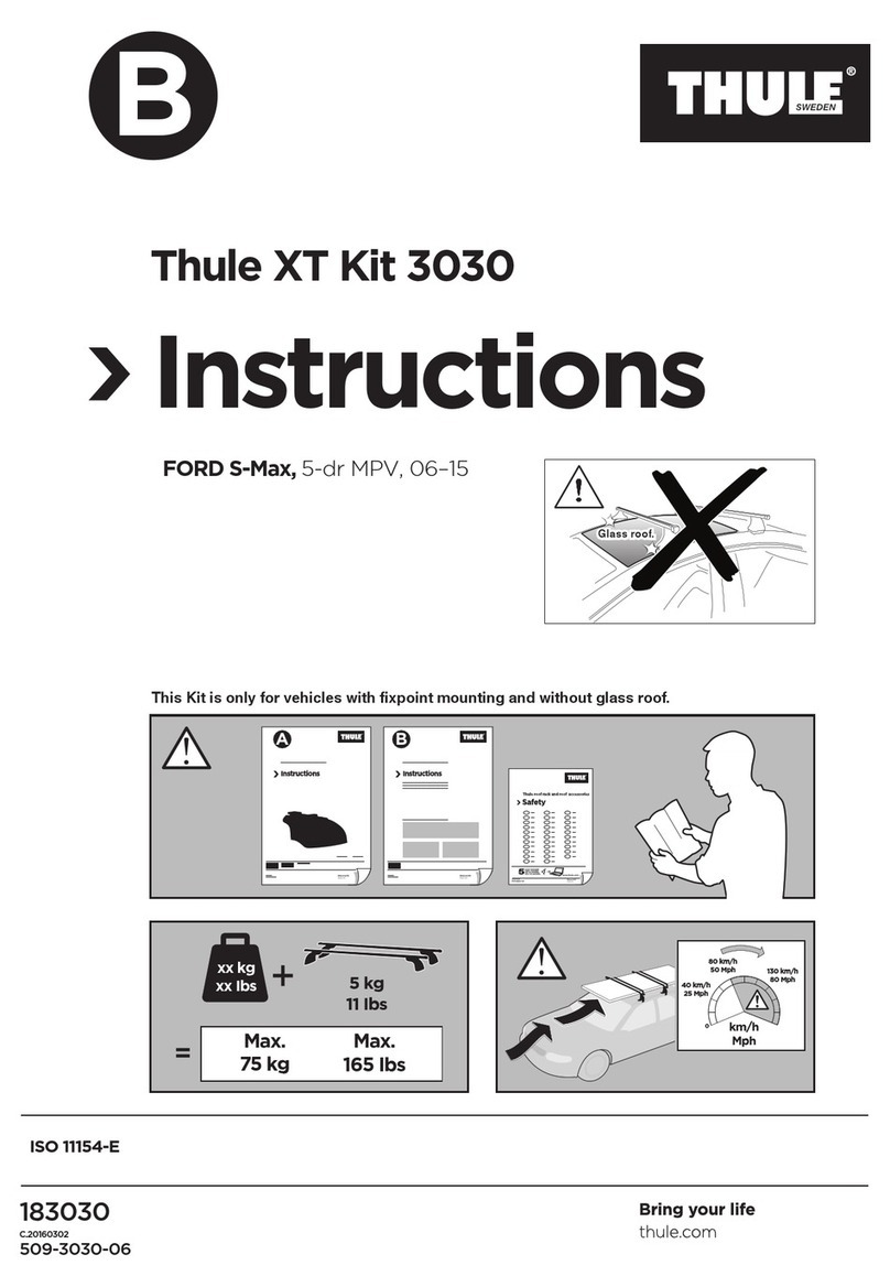
ELEVATE UPUT-RACK-ALUM-V2 User manual


Rev. 062118 DiscountRamps.com • 1-888-651-3431 Page 2
PARTS LIST
Prior to assembly and installation, make sure all parts are present, intact and undamaged. If you discover missing
and/or damaged parts, please contact our customer service using the information on page 1.
Item#
Description
Picture
Quantity
Item#
Description
Picture
Quantity
1
Crossbar
3
11
Connecting Plate
6
2
Support Bar
4
12
Connecting Plate
2
3
Driver Side Front/Passenger
Side Rear Leg Rail Mount
2
13
Thread Block
2
4
Passenger Side Front/Driver
Side Rear Leg Rail Mount
2
14
Splint
2
5
Upper Connecting Plate
4
15
Washer
4
6
Lower Connecting Plate
4
16
Plastic Sleeve
2
7
C-Clamp
8
17
Side Rail End Cap
4
8
Clamp Bolt Foot
8
18
Handle
2
9
Side Rail
4
19
Crossbar End Cap
6
10
Connecting Base
6
20
Thread Glue
1
Hardware kit
Item#
Description
Picture
Quantity
A
M10x25 hex socket flat head screw(21),10 flat washer(22),10
spring washer(23),Square nut(24)
32
B
M10x25 hex socket flat head screw(21),Square nut(24)
4
C
M10x16 hex socket flat head screw(25),10 flat washer(22),10
spring washer(23)
4
D
M10x16 hex socket flat head screw(25),10 spring washer(23)
4
E
M10x40 hex socket flat head screw(26)
16
F
T- nuts(27),10 flat washer(22),10 spring washer(23),Square
nut
8
G
M10x75 outer hex bolt(28),M10 outer hex nut(29)
8
H
M10x55 hex socket flat head screw(30),M10 locking nut(31)
8
I
ST4.8×16 cross recessed pan head tapping screws(32)
6

Rev. 062118 DiscountRamps.com • 1-888-651-3431 Page 3
Tools Required:
17mm Wrench (1 pc.) 6mm Allen Wrench (1 pc.) Tape Measure (1 pc)
ASSEMBLY/PARTS DIAGRAM

Rev. 062118 DiscountRamps.com • 1-888-651-3431 Page 4
ASSEMBLY PROCEDURES
Step 1: Support Arm Assembly
①ATTENTION! All M10x40
Button Head Screws (26), require
a drop of thread glue (20), and
installation/tightening within 2
minutes of glue application.
②Connect Upper Connecting
Plate (5), on Support Bar (2), and
secure with M10x40 Button
Head Screws (26), as shown.
Note: Use Thread Glue (20), on
screws as noted in ①.
③Connect Driver Side Front
Leg Rail (3), & Lower Connecting
Plate (6), to bottom of support
bar (2), using M10x40 Button
Head Screws (26), as shown.
Note: Use Thread Glue (20), on
screws as noted in ①.
④Secure Upper (5), and Lower
(6), Connecting Plates using
M10x55 Button Head Screws
(30) and M10 Lock Nuts (31), as
shown.
⑤The front driver side support
arm is now assembled. Confirm it
is correct using the diagrams
below.
⑥ Repeat this support arm
assembly procedure using the
Passenger Side Front Leg Rail
Mount (4). Then complete the
rear support arms in the same
manner.
CORRECT assembly example
for front and rear driver side
support arms.
The upper connecting base (5),
is level and parallel to rear leg
rail mount (3).
INCORRECT assembly
example for front and
rear driver side support
arms.
The upper connecting base (5),
is not level and parallel to rear
leg rail mount (3), because it is
facing the wrong direction.

Rev. 062118 DiscountRamps.com • 1-888-651-3431 Page 5
STEP 2. Crossbar Installation
①Attach Spring Washers (23),
Flat Washers (22), to M10x25
Button Head Screws (21), and
secure to upper connecting plate
(5), with M10 Nuts (24), as
shown. Do NOT tighten. Repeat
process for all four support arms.
②Support arms are now ready
for crossbar installation.
③Slide the center channel of
the Crossbar (1), onto the M10
Nuts (24), at the top of the
support arms as shown. Only
finger tighten bolts at this stage
to allow for crossbar positioning.
④Place the rack assembly on the truck and center the crossbar on the support arms as shown. Once all
is properly positioned, the M10x25 Button Head Screws (14), can be tightened to lock the crossbar in
place on the support arms. Repeat the same process for the rear rack assembly.
Equal overhang on both sides
Driver
Side
Passenger
Side

Rev. 062118 DiscountRamps.com • 1-888-651-3431 Page 6
STEP 3. Installation
①Attach an M10x75 Hex Head
Bolt (28), and M10 Hex Nut (29),
to each of the eight C-Clamps (7),
as shown.
②Position C-Clamp (7), close to
the base of the support arm so
that the tongue on the upper jaw
engages the groove in the Leg
Rail Mount (3), or (4). Place a
Clamp Bolt Foot (8) on the end of
the M10x75 Hex Head Bolt (28),
as shown.
③Tighten the M10x75 Hex
Head Bolt (28), and the M10 Hex
Nut (29), until entire assembly is
firmly affixed to the truck bed
rail. Install a second C-Clamp to
the same Leg Rail Mount at least
4” from the first.
④Continue the above procedure until you have installed two C-Clamps to each of the four Leg Rail
Mounts, securely affixing both crossbar assemblies to the truck bed rails as shown. WARNING! ALL
EIGHT C-CLAMPS MUST BE PROPERLY INSTALLED AS SHOWN FOR SAFE OPERATION OF THIS RACK.
Position clamps at
least 4” apart

Rev. 062118 DiscountRamps.com • 1-888-651-3431 Page 7
STEP 4. Side Rail Assembly and Installation
①Attach plastic sleeve (12), to
end of Side Rail (9), as shown.
②Attach Connecting Plate (16),
to end of Side Rail (9), using
M10x16 Button Head Screw (25),
Spring Washer (23), and Washer
(15), as shown.
③Attach Splint (14), and
Thread Block (13), to one end of
Side Rail (9), using M10x16
Button Head Screw (25), Spring
Washer (23), and Flat Washer
(22), as shown.
④ Attach a second Side Rail (9)
using the bolts and washers
shown below. Next, alternate
steps ⑤, ⑥ and ⑦ to achieve
side rail assembly configuration
shown in ⑧.
⑤Attach Handles (18), to end
of Side Rails as shown in ⑧
using M10x25 Button Head
Screws (21), and M10 Nuts (24).
⑥ Attach Ring Bolts (27), to
bottom of Side Rails (9), using
Spring Washers (23), Flat
Washers (22), and screw M10
Nut (24).
⑦ Install Connecting Plates (11), on Connecting
Bases (10), and attach to bottom of Side Rails (9),
using M10x25 Button Head Screws (21), Spring
Washers (23), Flat Washers (22), and M10 Nuts
(24). Do not tighten until installed on crossbars.
⑧ Repeat steps ① through ⑦ to complete two
side rail assemblies configured as shown below.
Note: Connecting Bases (10), cannot be positioned
under the joints linking the two side rail sections.
⑨ Attach side rail assemblies to crossbars using
M10x25 Button Head Screws (21), Spring Washers
(23), Flat Washers (22), and M10 Nuts (24). Do
not tighten until both side rails assemblies are
properly positioned on the crossbars.
⑩Tighten all 16 of the M10x25 Button Head
Screws (21), on the four Connecting Bases (10),
linking the side rails to the two rear crossbars
prior to installing and securing the front-most
crossbar.
STEP 5. Completing your rack.

Rev. 062118 DiscountRamps.com • 1-888-651-3431 Page 8
①Install all six Crossbar End Caps (19), and
secure in place using ST4.8×16 Phillips Head
Self-Tapping Screws (32), as shown.
② Install the four press-fit Side Rail End Caps as
shown.
③ Check to make sure all hardware has been securely tightened. Depending on the configuration of
your truck, your installed rack should resemble this diagram. Congratulations, your rack is now ready for
use. Please remember to haul your loads safely.

Rev. 062118 DiscountRamps.com • 1-888-651-3431 Page 9
Product Warranty and Liability
GENERAL PRODUCT WARRANTY: Products purchased from the Authorized Dealer (original place
of purchase) or Merchant (“Dealer”) will be free of defects in material and workmanship at the
time of receipt, and will meet the specifications stated at the place of purchase transaction or
online at the Dealer’s website, under normal use and service when correctly installed, operated
and maintained. This product warranty is effective for the period of time stated below, unless
otherwise stated in the product instructions or depicted in the product advertisement. All
Authorized Dealer warranties are NON-TRANSFERABLE and cover only the original end
purchaser. This limited warranty does not cover products purchased through non-authorized
dealers. Non-authorized dealer receipts are not accepted for warranty verification.
***Warranty claims must be made directly to the original place of purchase.***
WARRANTY PERIOD: This warranty remains in force for one year from the date of the product’s
accepted delivery. The Authorized Dealer offers a one year manufacturer’s warranty for most products
unless otherwise specified on the product advertisement.
WARRANTY SERVICE: The Authorized Dealer will replace any defective or malfunctioning part
at no charge, including payment of the shipping costs of parts or replacement product to and
from the
manufacturer. The purchaser is responsible for labor charges. If the product does not meet
specifica- tions as depicted in the advertisement, the Authorized Dealer will refund the full
purchase price of the product.
Questions regarding the warranty on a specific product and warranty claims should be directed to the
Authorized Dealer with whom the purchase transaction was made.
WARRANTY LIMITATIONS: The above warranty does not apply to products that are repaired, modi-
fied or altered by any party other than the Authorized Dealer; are subjected to unusual physical
stress or conditions (such as overloaded ramps or corrosion), natural disaster, governmental
actions, wars, strikes, labor disputes, riots, theft, vandalism, terrorism or any reason beyond
reasonable control; are damaged due to improper installation, misuse, abuse, accident or
negligence in use, storage, trans- portation or handling, or tampering; or to products that are
considered consumable items or items requiring repair or replacement due to normal wear and
tear.
Product should be inspected prior to signing for delivery. Product damage incurred during
shipping, unless noted on the Bill of Lading at the time of delivery, renders this warranty void.
LIMITED LIABILITY: In no event shall THE AUTHORIZED DEALER be liable to the purchaser or any
third party for any indirect, incidental, consequential, special, exemplary or punitive damages
arising out of the use of the product, including, without limitation, property damage, loss of value
of the prod- uct or any third party products that are used in or with the product, or loss of use of
the product or any third party products that are used in or with the product.
Other ELEVATE Automobile Accessories manuals
Popular Automobile Accessories manuals by other brands
Parrot
Parrot UNIKA installation manual
Westin
Westin 65-62076 installation instructions

Buyers Products Company
Buyers Products Company 8895560 Installation and operator's manual
injen technology
injen technology SP7035 installation instructions
Go Rhino
Go Rhino 3293B Assembly instructions
Jensen
Jensen BT360 user manual
Telit Wireless Solutions
Telit Wireless Solutions Sat 550 Installation and operation guide
LAS
LAS High Power WHEEL CLAMP quick start guide

Evolve
Evolve TRED Instructions for use
Car-Interface
Car-Interface CI-C1-RNSE manual

Waeco
Waeco PerfectView CAM50 Installation and operating manual

bosal
bosal 028781 Fitting instructions

