ELGA VEOLIA PURELAB User manual
WATER PURIFICATION
Operator Manual
®
MANU41319 VERSION D 08/20
Part No. LA824
DRAFT
07/8/2020

YOUR GUIDE TO THE CHORUS

Quick Start Guide Page 1 - 15
1. Manual Introduction Page 16
1.1 Health and Safety Page 16
1.2 Product Model Page 16
1.3 Use of this Manual Page 16
1.4 Installation Page 16
1.5 Environment Page 16
1.6 Commissioning Page 16
1.7 Customer Support Page 16
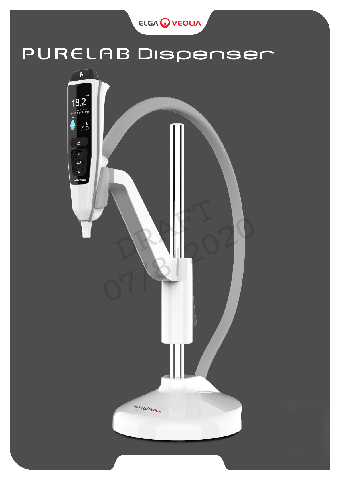
2. Guide to Your PURELAB®Dispenser Page 17
3. Main Display Settings and Button Operation Page 18
4. Product Consumables Page 19
5. Register Your Product Page 19
6. Quick Reference Guide Page 20 - 21
6.1 Manual Dispense Page 20
6.2 Continuous Dispense Page 20
6.3 Auto Volume Dispense Page 20
6.4 Deactivating - Auto Volume Dispense Page 21
6.5 ON - OFF, Main Menu and Accept Page 21
7. Maintenance Page 22
7.1 Replacing the Point-of-Use Filters LC134 / LC145 / LC197 Page 22
8. Customize Operation Page 23
8.1 Set Alarm Points Page 23
8.2 Advanced Data Logging Page 23
8.3 Software Update Page 23
9. Troubleshooting Page 24 - 25
10. Technical Specications Page 26
11. Warranty / Conditions of Sale Page 27
Copyright Note
The information contained in this document is the property of VWS (UK) Ltd, trading as ELGA VEOLIA , and is supplied without liability for errors or omissions.
No part of this document may be reproduced or used except as authorized by contract or other written permission from VWS (UK) Ltd.
The copyright and all restrictions on reproducing and use apply to all media in which this information may be placed.
VWS (UK) Ltd. Pursue a policy of continual product improvement and reserve the right to alter without notice the specication, design,
price or conditions of supply of any product or service.
© VWS (UK) Ltd. 2020 - All rights reserved. ELGA and PURELAB are registered trademarks of VWS (UK) Ltd.
CONTENT

Environment and Positioning
Control of Substances Hazardous to Health (COSHH)
Personal Protective Equipment (PPE)
Electricity
Clean dry indoor, temp 5 - 40°c, humidity max 80%, non-condensing.
Caution!
Do not connect to a pressurised water supply (potable or pretreated).
Failure to do so could result in damage to the installation.
WARNING!
The appliance coupler (mains lead) or power supply connected to the rear of the unit can be removed to isolate the
power supply. If access to this is restricted then it is recommended that access to the mains socket is easily
available to disconnect the power supply.
Please follow the safety information detailed below for the Quick Start Guide and Operator Manual.
WARNINGS ARE GIVEN WHERE FAILING TO OBSERVE THE INSTRUCTIONS COULD RESULT IN INJURY OR FATALITY.
Cautions are given where failure to observe the instructions could result in damage to the equipment, associated
equipment and processes.
Material safety data sheets covering the consumables are available upon request.
Note: Ensure the consumables are disposed of in accordance with local regulations.
Caution!
PURELAB Dispenser is not designed for use in fume cupboards where chemicals could damage the product.
Caution!
Installed on a at level worktop, PURELAB Dispenser can also be securely tted to a worktop using the
mounting bracket provided, please see Quick Start Guide - section 2 for details.
WARNING!
POSITION THE POWER SUPPLY SO THAT IT CANNOT COME INTO CONTACT WITH WATER.
MAINTENANCE MUST BE CARRIED OUT WITH PROPER PROTECTIVE EQUIPMENT THAT INCLUDES STERILE
LATEX NITRILE GLOVES CAT 3.
WARNING!
ONLY USE THE APPLIANCE COUPLER (MAINS LEAD) AND POWER SUPPLY PROVIDED, USE OF THESE WILL
ENSURE ADEQUATE EARTH PROTECTION. DISCONNECT ELECTRICAL MAINS POWER SUPPLY BEFORE ANY
MAINTENANCE WORK IS STARTED. IF THE EQUIPMENT IS USED IN A MANNER NOT SPECIFIED BY ELGA VEOLIA ,
THE PROTECTION PROVIDED BY THE EQUIPMENT MAY BE IMPAIRED.
WARNING!
HEALTH AND SAFETY NOTICES
®
®
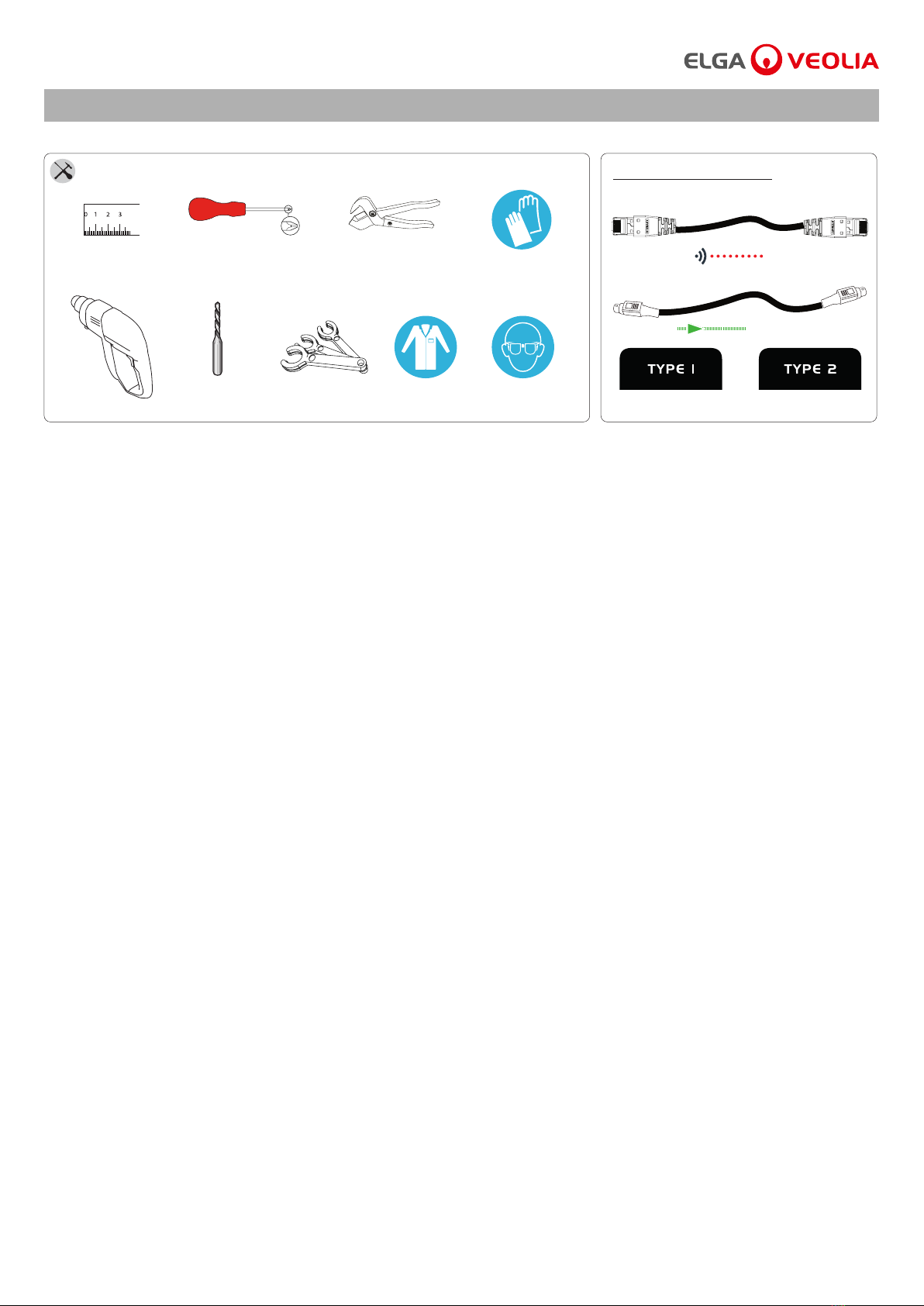
Items not supplied
EN14126
EN388 & EN374Tape Measure Plastic Pipe Cutters
Tube Keys Goggles
Ø3mm
Drill Bit
Drill
Phillips Screw Driver
Power
Handset Labels
COMMS
1 X
1 X
SUPPLIED PARTS
HEALTH AND SAFETY NOTICES
QUICK START GUIDE ENGLISH
WELCOME
HEALTH & SAFETY
Thank you for purchasing a PURELAB Dispenser, please read the Health and Safety notice before proceeding with this installation.
Dispenser Handset
LCD Display
Screen
Flexible
Dispenser Hose
Auto Volume Dispense Button
Dispense Button
Water Purity Display
Scrolling information bar -
bar indicating the status.
Auto Volume or
Reservoir Volume
Up Button
Accept Button
Down Button
Dispenser Tip
Worktop Mounting
Bracket
Handset Cradle
Height Adjustment
Button
Weighted Base
Please follow the safety information detailed in the front of the
Quick Start Guide. Failure to observe these instructions could result in
damage to the equipment and associated equipment resulting injury
or death.
ELGA VEOLIA
Tel: +44 (0) 203 567 7300
Email: info@elgalabwater.com Website: www.elgalabwater.com
Unit 10 Lane End Industrial Park, Lane End, High Wycombe, HP14 3BY
ELGA VEOLIA is the global laboratory water brand name of Veolia.
PURELAB is an ELGA trademark and technology.
Owning to a policy of continual improvement, we reserve the right to amend
the specications given in this document.
2020 ELGA VEOLIA / VWS (UK) Ltd. All rights reserved.
®
COMMS Port
COMMS Port
Port 5: ReturnPower
24V DC Power
24V DC
Port 1:
Inlet
®
® ®
PURELAB®Dispenser Operator Manual MANU41319 Version D 08/20 Page 1
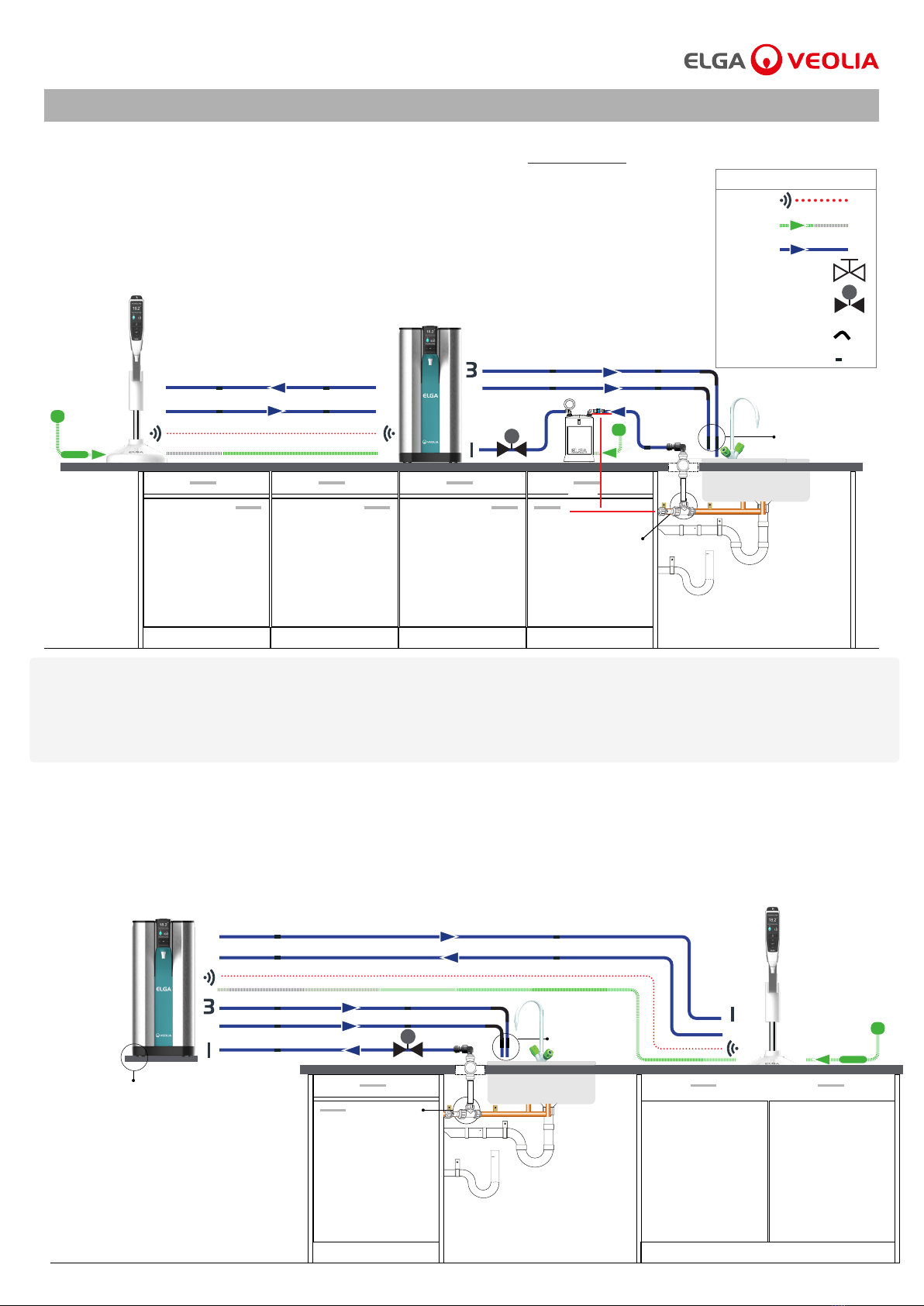
Quest Port 1: Feedwater Inlet
Quest Port 2: Overow
Quest Port 3: Drain
Quest Port 6: Dispenser Return
Quest Port 7: Dispenser Outlet
Dispenser Port 1: Inlet
Dispenser Port 5: Return
Example 1: 1 X PURELAB Quest RO/DI/UV or RO/DI - 1 X PURELAB Dispenser LA824 (Max 1 Dispenser) - LA648 Boost Pump
®
SYSTEM CONFIGURATION - PURELAB QUEST
COMMS
Key
Power
Water
15mm Valve
8mm Flow Bend
8mm Tube Clip
Regulator LA512
Optional - LA648 Boost Pump - for feedwater below <2.0 bar
Air Break Device
2
7
1
6
5
Max Distance 5000mm
InletOutlet
Quest
Dispenser Type 1
Type 1
LA648
MAX 1M
Potable
Feedwater
Connection
Quest Port 1: Feedwater Inlet
Quest Port 2: Overow
Quest Port 3: Drain
Quest Port 6: Dispenser Return
Quest Port 7: Dispenser Outlet
Dispenser Port 1: Inlet
Dispenser Port 5: Return
6
5
7
Example 2: 1 X PURELAB Quest RO/DI/UV or RO/DI - 1 X PURELAB Dispenser LA824 - Wall Mounting Bracket LA735
®®
Wall Mounting Bracket LA735 (INST39088)
Air Break Device
2
Max Distance 5000mmQuest
Type 1
Dispenser Type 1
Potable
Feedwater
Connection
®
Existing system conguration: If you are connecting a PURELAB Dispenser to an existing system conguration, please ensure all of your products
are up to date and using the latest software. To nd the software version of your existing system, simply turn the power o by the wall and back on
again and the current software version number will be displayed in the bottom right-hand corner of the screen. If your software version number is
older than the one listed on the website at www.elgalabwater.com/customize, then please perform a software update,
see section 8.3 'Software Update' in this operator manual.
®
PURELAB®Dispenser Operator Manual MANU41319 Version D 08/20 Page 2

SYSTEM CONFIGURATION - PURELAB CHORUS 1 ANR/LSC/GSC
Chorus Port 1: Feedwater Inlet
Chorus Port 3: Drain
Chorus Port 4: Product Outlet
Chorus Port 5: Return
Chorus Port 6: Power
Chorus Port 7: Comms
Chorus Port 8: Power
Chorus Port 9: Comms
Chorus Reservoir Port 1: Inlet
Chorus Reservoir Port 4a: Outlet
Chorus Reservoir Port 4b: Outlet
Chorus Reservoir J1: Comms
Chorus Reservoir J2: Comms
Dispenser Port 1: Inlet
Dispenser Port 5: Return
Halo Dispenser Port 1: Inlet
Halo Dispenser Port 5: Return
Halo Dispenser Port 6: Power
Halo Dispenser Port 7: Comms
Halo Dispenser Port 8: Power
Halo Dispenser Port 9: Comms
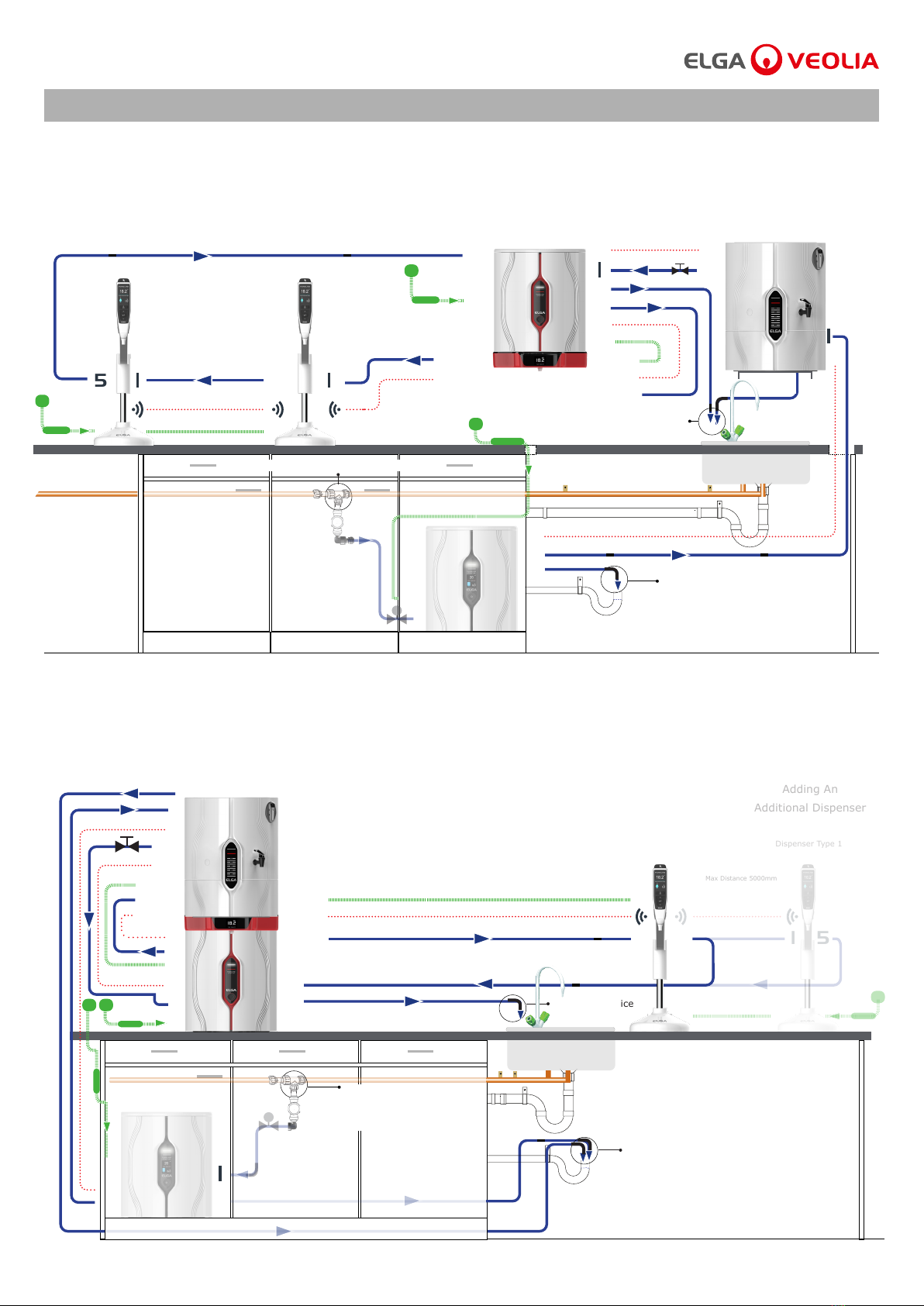
Example 1: 2 X PURELAB Chorus 3 RO or 2 X PURELAB Chorus 2 RO/DI - 1 X PURELAB Chorus 1 - 3 X PURELAB Dispensers LA824
(Max 4 Dispensers) - LA759 60L Reservoir or LA760 100L Reservoir
® ® ® ®
3
4
6
9
7
7
7
7
9
5
555
Air Break Device
Air Break Device
Chorus 3 RO or Chorus 2 RO/DI lls an external reservoir with puried Type 3 or Type 2 water, which then feeds a Chorus 1
to produce Type 1 water.
New system conguration:
1. Commission Chorus 3 RO or Chorus 2 RO/DI systems rst, directing reservoir port: 4a to drain during this procedure.
(Please refer to operator manual Chorus 3 RO MANU39996 or Chorus 2 RO/DI MANU40003 for commissioning instructions)
2. Once the reservoir is full, open reservoir port:4a manual valve to Chorus 1 port 1: Feedwater inlet and continue to commission Chorus 1
with the PURELAB Dispensers connected.
3. Chorus 1 is set in pre-commisioning mode and will automatically direct water to drain during this procedure.
(Please refer to operator manual Chorus 1 MANU39998 for commissioning instructions)
Existing system conguration: If you are connecting a PURELAB Dispenser to an existing system conguration, please ensure all of your products
are up to date and using the latest software. To nd the software version of your existing system, simply turn the power o by the wall and back on
again and the current software version number will be displayed in the bottom right-hand corner of the screen. If your software version number is
older than the one listed on the website at www.elgalabwater.com/customize, then please perform a software update,
see section 8.3 'Software Update' in this operator manual.
Potable Mains Feedwater Connection
Air Break
Device
4
J1 J2
4a
4b
4
33
8 66
Reservoir Overow
COMMS
Key
Power
Water
Valve
15mm Valve
8mm Flow Bend
8mm Tube Clip
Regulator LA512
8mm Equal T
Dispenser Type 1 Dispenser Type 1 Dispenser Type 1
Chorus 3 RO or 2 RO/DI Chorus 3 RO or 2 RO/DI Reservoir 60L or 100L
Chorus 1
Type 3 or 2
Max Distance 5000mm Max Distance 5000mm
®
Outlet to Application
Air Break Device
PURELAB®Dispenser Operator Manual MANU41319 Version D 08/20 Page 3
®
Air Break Device
SYSTEM CONFIGURATION - PURELAB CHORUS 1 ANR/LSC/GSC
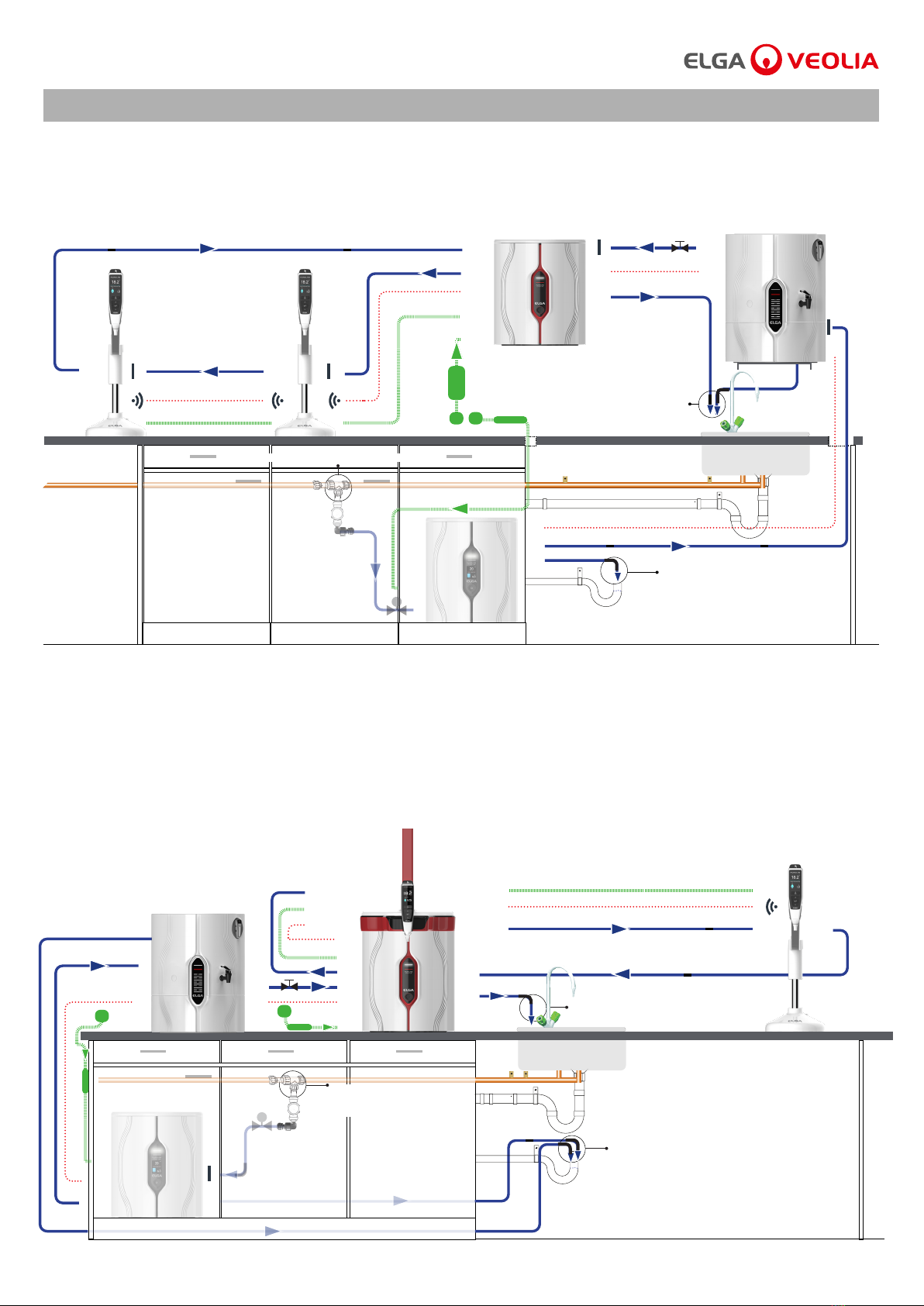
Example 2: 1 X PURELAB Chorus 3 RO or 1 X PURELAB Chorus 2 RO/DI - 1 X PURELAB Chorus 1 - 2 X PURELAB Dispensers LA824 -
LA757 15L Reservoir or LA758 30L Reservoir - Halo Dispenser Wall Mounting Bracket LA768 - Chorus Reservoir Bracket LA770
1 X PURELAB Halo Dispenser LA754 or LA755
Example 3: 1 X PURELAB Chorus 3 RO or 1 X PURELAB Chorus 2 RO/DI - 1 X PURELAB Chorus 1 - 1 X PURELAB Chorus Halo Dispenser LA754 or
LA755 - 1 X PURELAB Dispenser LA824 - LA757 15L Reservoir or LA758 30L Reservoir
® ® ® ®
Air Break Device
Air Break Device
Air Break Device
7 J2
5
1
Halo 5
Halo 9 Halo 7
Halo 6
Halo 1
Halo 8
5
5
3
5
3
4
7
J1
J2
J1
1
6
6
4
8
9
7
1
4a
5
3
3
4
8
9
5
6
1
'See Chorus 1 system conguration notes'
'See Chorus 1 system conguration notes'
4a
Dispenser Type 1
Dispenser Type 1
Dispenser Type 1 Dispenser Type 1
Chorus 3 RO or 2 RO/DI
Chorus 3 RO or 2 RO/DI*
Type 3 or 2
Chorus 1 Reservoir 15L or 30L
Reservoir 15L or 30L
Reservoir Overow
Chorus 1
Type 3 or 2
Type 1
1
6
4
7
® ®® ® ®
Adding An
Additional Dispenser
Max Distance 5000mm
Max Distance 5000mm
Max Distance 5000mm
Reservoir
Overow
Chorus 3 RO or 2 RO/DI
Halo 1
Halo 9
Halo 8
Halo 5
Halo 7
Potable Mains Feedwater Connection
®
Potable Mains
Feedwater Connection
®
Basic or Advanced
Halo Dispenser
Basic or Advanced
Halo Dispenser
Type 1
PURELAB®Dispenser Operator Manual MANU41319 Version D 08/20 Page 4
SYSTEM CONFIGURATION - PURELAB CHORUS 1 ANR/LSC/GSC
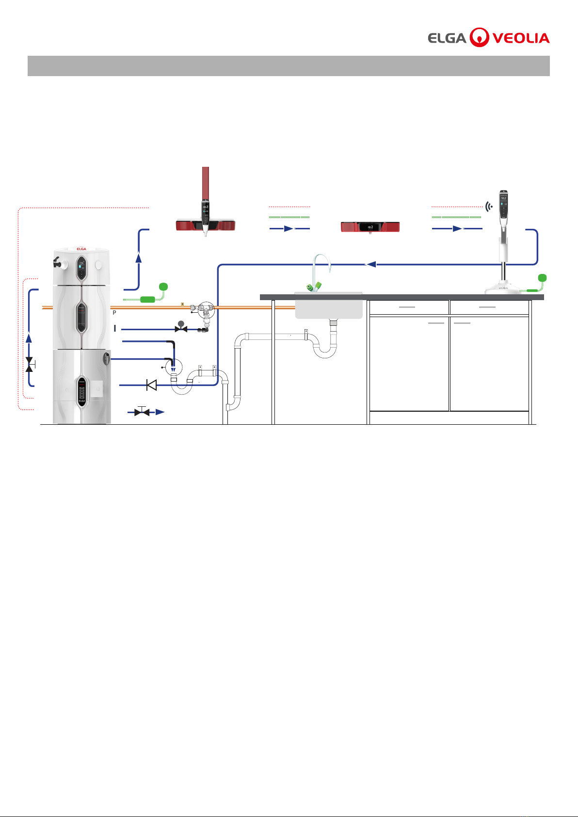
Example 4: 1 X PURELAB Chorus 3 RO or 1 X PURELAB Chorus 2 RO/DI - 1 X PURELAB Chorus 1 - 2 X PURELAB Dispensers LA824 -
LA757 15L Reservoir or LA758 30L Reservoir - Chorus Wall Mounting Bracket LA795 - Chorus Reservoir Bracket LA770
Example 5: 1 X PURELAB Chorus 3 RO or 1 X PURELAB Chorus 2 RO/DI - 1 X PURELAB Chorus 1 - 1 X PURELAB Chorus Halo Dispenser LA754 or
LA755 or LA756 - 1 X PURELAB Dispenser LA824 - LA757 15L Reservoir or LA758 30L Reservoir
® ® ® ®
Air Break Device
Air Break Device
Air Break Device
Air Break Device
7 J2
5
1
Halo 9
Halo 8
Halo 1
5
3
5
3
4
7
J1
6
3
5
4
8
9
1
6
7
4a
J2
1
3
4
5
9
6
8
1
'See Chorus 1 system conguration notes'
'See Chorus 1 system conguration notes'
4a
Dispenser Type 1
Flexible Halo Dispenser Type 1
Dispenser Type 1 Dispenser Type 1
Chorus 3 RO or 2 RO/DI
Chorus 3 RO or 2 RO/DI*
Type 3 or 2
Chorus 1 Reservoir 15L or 30L
Reservoir Overow
Chorus 1 Chorus 1
6
4
7
® ® ® ®
Max Distance 5000mm
Max Distance 5000mm
Reservoir
Overow
Chorus 3 RO or 2 RO/DI
Halo 5
Halo 7
Potable Mains Feedwater Connection
Potable Mains
Feedwater Connection
Reservoir 15L or 30L
Type 3 or 2
J1
Halo 6
®
PURELAB®Dispenser Operator Manual MANU41319 Version D 08/20 Page 5

SYSTEM CONFIGURATION - PURELAB CHORUS 1 COMPLETE AND 2+ NON EDI
Chorus Port 1: Feedwater Inlet
Chorus Port 3: Drain
Chorus Port 4: Product Outlet
Chorus Port 5: Return
Chorus Port 6: Power
Chorus Port 7: Comms
Chorus Reservoir Port 1: Inlet
Chorus Reservoir Port 4a: Outlet
Chorus Reservoir Port 4b: Outlet
Chorus Reservoir J1: Comms
Chorus Reservoir J2: Comms
Dispenser Port 1: Inlet
Dispenser Port 5: Return
Halo Dispenser Port 1: Inlet
Halo Dispenser Port 5: Return
Halo Dispenser Port 6: Power
Halo Dispenser Port 7: Comms
Halo Dispenser Port 8: Power
Halo Dispenser Port 9: Comms
Example 1: 1 X PURELAB Chorus 1 Complete or PURELAB Chorus 2+ (Non EDI) -3 X PURELAB Dispensers LA824 (Max 3 Dispensers) -
LA759 60L Reservoir or LA760 100L Reservoir
® ®
Chorus 1 Complete and 2+ recirculate puried water throught the reservoir for repeated exposure to the purifying technologies.
New system conguration:
1. Remove and relocate Non-Return-Valve before starting the commissiong procedure.
(Please refer to operator manual MANU40932 section 7.2 for details)
2. Commission PURELAB Chorus 1 Complete or PURELAB Chorus 2+ system with the dispensers connected, redirecting reservoir port: 4b to drain
during this procedure (Please refer to operator manual MANU40932 section 5.5 for commissioning instructions).
Existing system conguration: If you are connecting a PURELAB Dispenser to an existing system conguration, please ensure all of your products
are up to date and using the latest software. To nd the software version of your existing system, simply turn the power o by the wall and back on
again and the current software version number will be displayed in the bottom right-hand corner of the screen. If your software version number is
older than the one listed on the website at www.elgalabwater.com/customize, then please perform a software update,
see section 8.3 'Software Update' in this operator manual.
®®
COMMS
Key
Power
Water
Valve
Non-Return-Valve
15mm Valve
8mm Flow Bend
8mm Tube Clip
Regulator LA512
®
Max Distance 5000mmMax Distance 5000mm
NRV
Air Break Device
Outlet to Application
Reservoir Overow
11 55
5
6
7
4a
J2
1
4b
3
45
Max Distance 5000mm
Adding An
Additional Dispenser
Chorus 1 Complete or 2+ (Non EDI)
Chorus Reservoir 60L or 100L
1
1
Dispenser Type 1 or Type 2+ Dispenser Type 1 or Type 2+
Dispenser Type 1 or Type 2+
Air Break Device
Potable Mains
Feedwater Connection
J1
®
PURELAB®Dispenser Operator Manual MANU41319 Version D 08/20 Page 6
SYSTEM CONFIGURATION - PURELAB CHORUS 1 COMPLETE AND 2+ NON EDI
Example 2: 1 X PURELAB Chorus 1 Complete or PURELAB Chorus 2+ (Non EDI) -1 X PURELAB Dispenser LA824 -
LA757 15L Reservoir or LA758 30L Reservoir - 2 X PURELAB Chorus Halo Dispenser LA754 or LA755 or LA756
® ® ®
'See Chorus 1 Complete and 2+ (Non EDI) system conguration notes'
Potable Mains Feedwater
Connection
Reservoir Overow
Air Break Device
1
3
4b
4a
4
6
5
1
7
Chorus Reservoir 15L or 30L
1
5
Max Distance 5000mmMax Distance 5000mm Max Distance 5000mm
Dispenser Type 1 or Type 2+Flexible Halo Dispenser Type 1 or Type 2+
Outlet to Application
NRV
J1
J2
Halo 1 Halo 1
Halo 8
Halo 5
Halo 6
Halo 5
Halo 6
Halo 7Halo 7 Halo 9
Halo 9
®
Basic or Advanced Halo Dispenser Type 1 or Type 2+
Chorus 1 Complete or 2+ (Non EDI)
PURELAB®Dispenser Operator Manual MANU41319 Version D 08/20 Page 7

SYSTEM CONFIGURATION - PURELAB CHORUS 2+ EDI
Chorus Port 1: Feedwater Inlet
Chorus Port 2: EDI Drain
Chorus Port 3: Drain
Chorus Port 4: Product Outlet
Chorus Port 5: Return
Chorus Port 6: Power
Chorus Port 7: Comms
Chorus Reservoir Port 1: Inlet
Chorus Reservoir Port 4a: Outlet
Chorus Reservoir Port 4b: Outlet
Chorus Reservoir J1: Comms
Chorus Reservoir J2: Comms
Dispenser Port 1: Inlet
Dispenser Port 5: Return
Halo Dispenser Port 1: Inlet
Halo Dispenser Port 5: Return
Halo Dispenser Port 6: Power
Halo Dispenser Port 7: Comms
Halo Dispenser Port 8: Power
Halo Dispenser Port 9: Comms
Example 1: 1 X PURELAB Chorus 2+ (EDI) - 3 X PURELAB Dispensers (Max 3 Dispensers) - LA759 60L Reservoir or LA760 100L Reservoir
®®
Chorus 2+ EDI recirculate puried water throught the reservoir for repeated exposure to the purifying technologies.
New System conguration:
1. Remove and relocate Non-Return-Valve before starting the commissiong procedure.
(Please refer to operator manual MANU40932 section 7.2 for details)
2. Commission PURELAB Chorus 2+ EDI with the PURELAB Dispensers connected, water will be automatically redirected to drain through an internal
ush valve (V2) during this procedure. (Please refer to operator manual MANU40932 section 5.6 for commissioning instructions)
3. Once commissioning is completed the internal EDI lter module will need 'bleeding' before puried water can be dispensed from the Chorus 2+ tap
or dispensers. (Please refer to operator manual MANU40932 section 5.6 for instructions)
Existing system conguration: If you are connecting a PURELAB Dispenser to an existing system conguration, please ensure all of your products
are up to date and using the latest software. To nd the software version of your existing system, simply turn the power o by the wall and back on
again and the current software version number will be displayed in the bottom right-hand corner of the screen. If your software version number is
older than the one listed on the website at www.elgalabwater.com/customize, then please perform a software update,
see section 8.3 'Software Update' in this operator manual.
® ®
Max Distance 5000mmMax Distance 5000mm
NRV
Air Break Device
Outlet to Application
Reservoir Overow
11 55
5
6
7
4a
J2
1
4b
3
4
5
Max Distance 5000mm
Adding An
Additional Dispenser
Chorus 2+ EDI
Chorus Reservoir 60L or 100L
1
1
Dispenser Type 2+ Dispenser Type 2+
Dispenser Type 2+
Air Break Device
Potable Mains
Feedwater Connection
J1
COMMS
Key
Power
Water
Valve
Non-Return-Valve
15mm Valve
8mm Flow Bend
8mm Tube Clip
Regulator LA512
®
2
PURELAB®Dispenser Operator Manual MANU41319 Version D 08/20 Page 8

SYSTEM CONFIGURATION - PURELAB CHORUS 2+ EDI
Example 2: 1 X PURELAB Chorus 2+ (EDI) - 1 X PURELAB Dispenser LA824 - LA757 15L Reservoir or LA758 30L Reservoir -
2 X PURELAB Chorus Halo Dispenser LA754 or LA755 or LA756
®
®
®
'See Chorus 2+ (EDI) system conguration notes'
Potable Mains Feedwater
Connection
Reservoir Overow
Air Break Device
1
3
2
4b
4a
4
6
5
1
7
Chorus 2+ EDI
Chorus Reservoir 15L or 30L
1
5
Max Distance 5000mmMax Distance 5000mm Max Distance 5000mm
Dispenser Type 2+Basic or Advanced Halo Dispenser Type 2+
Flexible Halo Dispenser Type 2+
Outlet to Application
NRV
J1
J2
Halo 1 Halo 1
Halo 8
Halo 5
Halo 6
Halo 5
Halo 6
Halo 7Halo 7 Halo 9
Halo 9
PURELAB®Dispenser Operator Manual MANU41319 Version D 08/20 Page 9
SET-UP ENGLISH
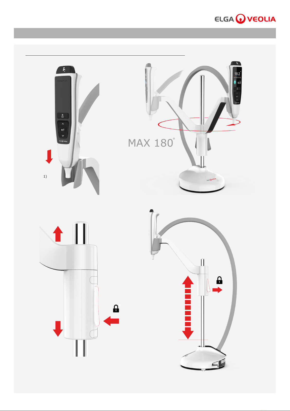
HOW TO ASSEMBLE AND MAKE HEIGHT ADJUSTMENTS
1
(Fig.1) (Fig.2)
a) Insert the handset set into the cradle as shown. (Fig.1)
c) Press and hold the height adjustment button to slide
the handset arm up and down. (Fig.3)
b) Rotate the handset. (Fig.2)
d) When you have found the perfect height, release the hight adjustment
button to lock into position. (Fig.4)
(Fig.3) (Fig.4)
MAX 180
˚
PURELAB®Dispenser Operator Manual MANU41319 Version D 08/20 Page 10
SET - UP
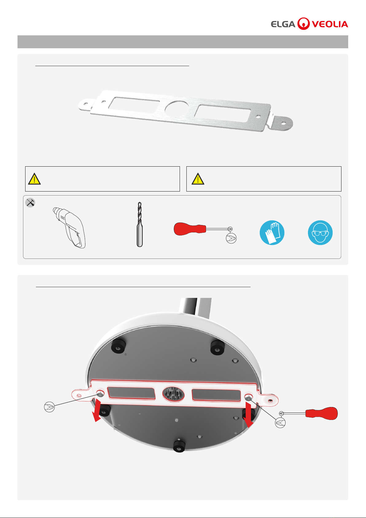
REMOVING THE SUPPLIED WORKTOP MOUNTING BRACKET
OPTIONAL WORKTOP MOUNTING BRACKET
2
3
(Fig.5)
(Fig.6)
a) Undo the xing screws screw from the base of the PURELAB Dispenser to remove the mounting bracket.
(Fig.6)
This is an optional attachment, please skip to section 7 in the Quick Start Guide if you do not need to t this sercuring bracket.
Items not supplied
EN388 & EN374Phillips Screw DriverØ3mm Drill BitDrill Goggles
Caution! Please read the Health and Safety Notices in the
front of the Quick Start Guide before proceeding
with this installation.
Caution! This bracket is only suitable for wooden worktops.
PURELAB®Dispenser Operator Manual MANU41319 Version D 08/20 Page 11

SET - UP
MARK AND DRILLING THE HOLES REASSEMBLE THE BRACKET
FIXING THE PURELAB DISPENSER TO THE WORKTOP
4 5
6
a) Mark and drill two holes into the wooden worktop to a depth of
30mm using an Ø3mm pilot drill bit. (Fig.7)
Ø3mm
a) Reassemble the mounting bracket back onto the base
as shown above. (Fig.8)
a) Insert the xing screws into the screw cap washers. (Fig.9)
Screw cap
Fixing Screw
Screw cap washer
b) Fix the screws into the pre drilled holes and push the screw caps over the screw heads. (Fig.9)
Bracket installations completed
(Fig.7)
(Fig.8)
(Fig.9)
PURELAB®Dispenser Operator Manual MANU41319 Version D 08/20 Page 12

SET - UP
CONNECT THE WATER INLET
CONNECT THE WATER RETURN
7
8
(Fig.12) (Fig.13)
a) Remove the transit plug from Port 5 water Return connection.
(Fig.12)
b) Using the tube supplied, rmly push one end securely into the
Port 5 water Return connection. Use the ow bends provided to
mould the tube into position. (Fig.13)
b) Using the tube supplied, rmly push one end securely into
Port 1 inlet connection. Use the ow bends provided to mould
the tube into position. (Fig.11)
Push in collet
Remove Transit Plug
a) Remove the transit plug from Port 1 water inlet connection.
(Fig.10)
Push in collet
Remove Transit Plug
(Fig.10) (Fig.11)
Flow Bends
Transit Plug
PURELAB®Dispenser Operator Manual MANU41319 Version D 08/20 Page 13
Comms cable from main
product or reservoir port
Comms cable from main
product or reservoir port
Power supply
(Power supply is supplied with main product)
SET - UP
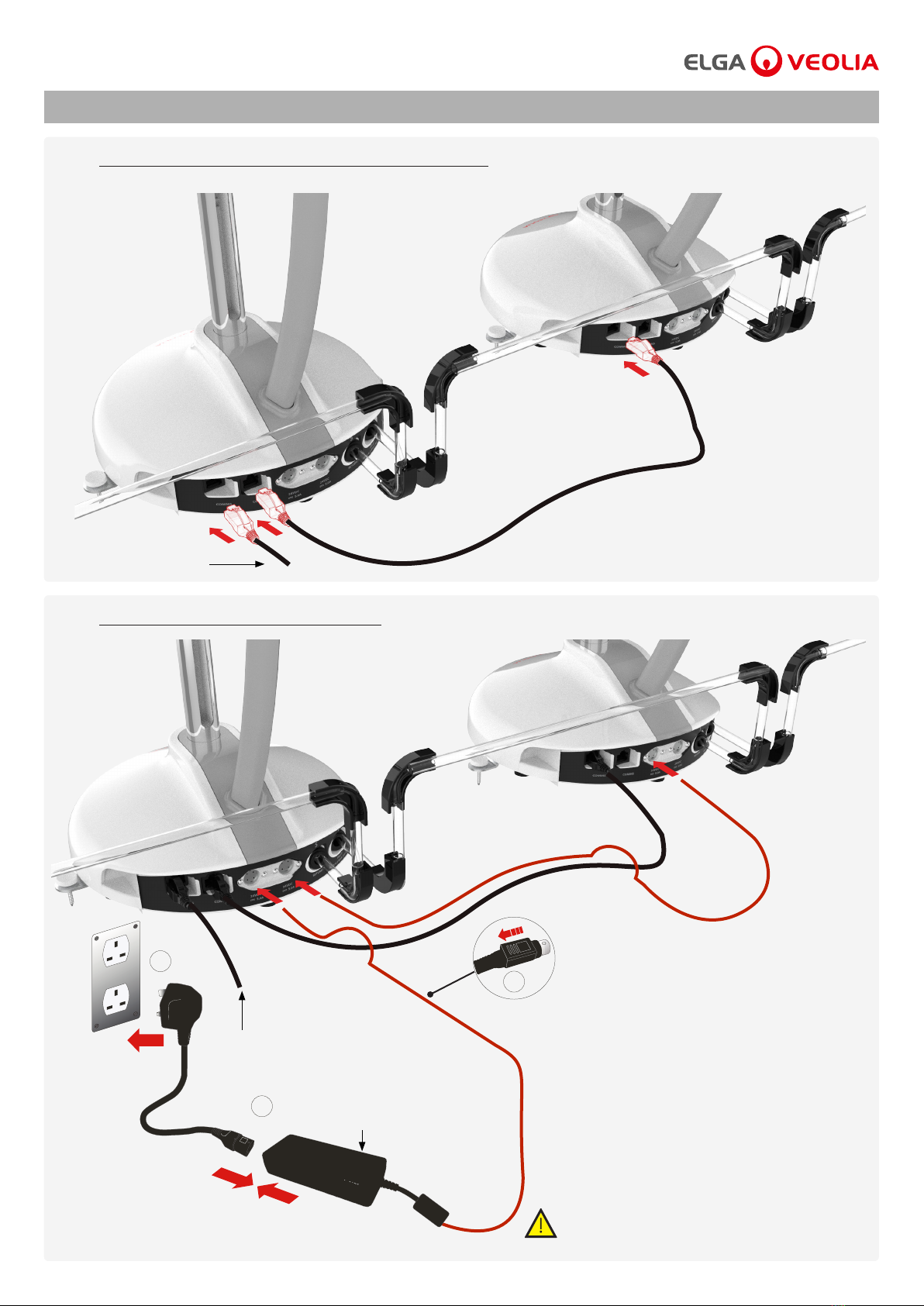
CONNECT THE COMMUNICATIONS CABLES
CONNECT THE POWER CABLES
9
10
a) Link the comms cables as shown above,
connections may vary depending on your
system conguration. (Fig.14)
a) Link the power cables as shown above,
connections may vary depending on your
system conguration. (Fig.15)
Caution!
Only use the power supply provided by ELGA VEOLIA.
3
2
1
(Fig.14)
(Fig.15)
PURELAB®Dispenser Operator Manual MANU41319 Version D 08/20 Page 14
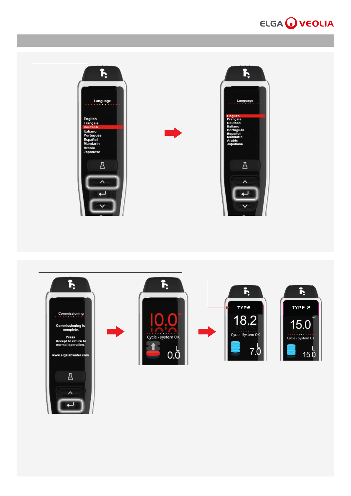
SET - UP
11
12
SET LANGUAGE
FOLLOW THE ON SCREEN INSTRUCTIONS
a) Press up and down buttons to select your language. (Fig.16)
(Language section will only appear on screen if you are setting up a new system conguration.)
(The Commissioning procedure will only appear on screen if you are setting up a new system conguration.
When connecting to an existing system conguration, wait for the purity to be displayed before dispensing)
a) For new system system congurations,
follow the on screen commissioning
instructions. (Fig.18)
b) After completing the commissioning
procedure, please wait for the
reservoir to ll and reach full purity
before dispensing any water. (Fig.19)
(Water Purity Alarm will be active
during the commissioning)
C) When full purity is reached reached on your
Type 1 or Type 2 system conguration
you can dispense puried water from the
PURELAB Dispenser. (Fig.20)
Type 1 or Type 2 handset label.
b) Press accept to conrm. (Fig.17)
(Fig.16)
(Fig.18)
(Fig.19) (Fig.20)
(Fig.17)
PURELAB®Dispenser Operator Manual MANU41319 Version D 08/20 Page 15
Table of contents


