ELGO Electric Z20-SN105-024 User manual

Mini position indicator
with magnetic length measuring system
(ELGO sensor MS20.60 and magnetic tape MB20.50)
With sign
5 digits pulse factor
Programmable decimal point
Digital brightness control
SERIE Z20-SN105-024
(Z20-005 with enable of parameter settings by hardware link)
Z20-105-E_41-04.pdf
Doku-Art.-Nr.799000235

1. INTRODUCTION 3
2. OPERATING INSTRUCTIONS 3
3. THE MAGNETIC LENGTH-MEASURING-SYSTEM 3
Essential Features 3
High Accuracy 3
Simple Mounting 4
Protection Class 4
Connections 4
4. THE COMPONENTS 5
1. Magnetic tape MB 20.50 5
2. Sensor MS 20.60 6
5. PARAMETER SETTING 7
Registers 7
Programming-example: 7
6. HINTS FOR INSTALLATION AND OPERATION 8
Hints for Operation in Electrical panels 8
Hints on mounting the Tape MB20.50 8
7. TECHNICAL SPECIFICATIONS 9
Magnetic Sensor MS 20.60 9
Magnetic Tape MB 20.50 9
Indicator 9
8. DIMENSIONS 10
9. TYPE DESIGNATION 11
Accessories 11
10. LIABILITY EXCLUSION / GUARANTEE 12
2

1. Introduction
This small, compact instrument has an 8 mm high, red LED display and provides a convenient,
precise and easily readable indication of position. Using the dust-tight keypad (and external signal
if required) the display can be reset or preset a datum value.
The unit will operate with Elgo magnetic scale system and provides a rugged cost effective quality
panel mounting instrument.
2. Operating Instructions
It is possible to alter the indicated value, using the keypad located on front.
To reset the indicator:
Press „F“ and simultaneously „RESET“
To set indicator a required datum:
Press „F“ and simultaneously „SET“
The indicator begins to count up (adding) at three progressive speed rates:
Rate 1 : at 1 Hz for 10 sec.
Rate 2 : at 10 HZ for 10 sec.
Rate 3 : at 1000 HZ as long as pushbutton are depressed.
It is necessary, shortly before the desired value is reached, to release the button and reactivate, so
as to approach position at the slowest rate.
A fix reference value can be deposited in Parameter 09. This additional function must be enabled
in Parameter 16 before (see page 7).
3. The magnetic Length-measuring-system
Essential Features
The flexible tape is precisely calibrated with north and south poles. A Sensor picks up these
divisions. The space between poles on the tape provides an analogue sinusoidal voltage output for
the sensor.
High Accuracy
With a maximum cumulative error of 0.01 mm/m and resolution of 0.01 mm this type of measuring
system can achieve a longer length (up to 25 m) with better accuracy. Backlash, slip, screw pitch,
gearbox or other mechanical errors eliminated with this direct measurement system.
3

Simple Mounting
The tape is simple to attach to the machine (e.g. by means of double sided sticky tape). Due to its
high flexibility it can cope with uneven surfaces ore radii without affecting accuracy. A second steel
tape is fitted on top of the magnetic tape, to protect it. The equipment will operate satisfactorily
with a measuring gap of 0.1 to 2.0 mm.
Protection Class
The magnetic measuring system offers the greatest protection against hostile environments.
Sensor and tape are protected to IP65.
Connections
Connections are by means of simple plug in connectors. This connector are readily removable and
easily wired.
+ 15… 30 VDC
RESET SET
Power Supply
Schalter
-0V(GND)
1 2 3 4 5 6 7 8 9 10
Connector for Senso
r
Parameter settings:
Jumper enabled
no jumper disabled
4

4. The components
1. Magnetic tape MB 20.50
The complete tape comprises 3 components:
Can be supplied in lengths from 0,5 - 32 m
A
The magnetized, highly flexible rubber tape, connected on the bottom with:
B
A magnetized, flexible steel tape. This steel tape protects the rubber tape from mechanical
damages and is at the same time a magnetic short circuit. This increases significantly the
functional security under extreme magnetic influences. Aand Bare already factory-bonded.
C
To keep the flexibility for transport and installation, the third part, also a steel tape (magnetic
permeable), is delivered separately. It serves for mechanical protection of the rubber tape and
must be stuck on the magnetic rubber tape after installation.
L
10m
m
Sensor side
Mounting side
CAB
1,8mm
5

2. Sensor MS 20.60
The sensor head provides an analog signal.
The sensor is connected directly to the indicator.
Dimensions:
Over the distance X, the gap between sensor and measuring tape must not be larger than
0.1… 2.0 mm.
Sensor cable length - signal processing
Z20.005 is a combination of the indicator and the sensor.
The sensor wire is available in the following standard-lengths:
1m, 3m, 5m, 8m, 10m and 15 m.
Other lengths on request.
17+/-0,244
3,6
11,2 +/- 0,2
30
10 7X
Distance max. 2,0 mm
15
10
6
1
6

5. Parameter setting
To enter the set up-mode a link must be done between Connector Pin 2 and 4, at the rear of
the unit (see jumper on image / page 4), to enable the set up level. The parameter entry will be
activated by pressing the 3 front located keys for app. 3 seconds at the same time.
In parameter setting mode, the keypad has the following functions:
Fentry in to parameter-selection and parameter-end of programming
RESET select digit to be changed
SET increment a digit between 0 at 9
To disable parameter settings again, remove the jumper at Pin 2 and 4 (rear).
Registers
Par Function Range
03 Decimal point 0…3
07 Sign 0 = +/- active 1 = +/- inactive
08 Pulse factor 0.0001… 9.9999
09 Datum value 0.0001… 9.9999
14 Display brightness
Set 0-9
0… 9 = dark
16 * Enable of Par 09 0 = Nr.09 disabled
2 = Nr.09 enabled
Programming-example:
Modification of pulse factor:
1. Press button F / Reset / Set simultaneously for 5 sec.
2. Press „F“ button
3. Press „RESET“ button to select digit 1 for alteration
4. Press „SET“ button 8 times to get parameter-number 08 in the display
5. Press „F“ button to select parameter-value
6. Press „RESET“ button to select the digit to be changed
7. Press „SET“ button to increment the digit to be changed
8. Press „F“ button to store the value to the internal Ram and prepare
indicator for change of other parameters.
9. Press button F / Reset / Set simultaneously
Now the new factor is stored and the indicator works in normal operation mode.
7

6. Hints for installation and Operation
Hints for Operation in Electrical panels
This position indicator is designed and constructed for use in arduous industrial applications and as
immune to electrical interference as possible. Care should however be taken when fitting electronic
equipment into machinery.
1. Electronic units should be mounted away from inductive and capacitate interference.
2. Protect against overvoltage.
3. Protect against over temperature.
4. Run low voltage cables separate to high voltage/high power cables.
5. Screen encoder cables and input signal cables. Tie screen to zero (terminal 1) at controller;
leave insulated at other end.
6. Suppress all relays, contractors, solenoids, brakes and other coils in cabinet and on machine. Fit
diodes across dc coils. Fit 0,1 µF + 100 Ωacross ac coils. Failure to follow the above logical
simple instructions could lead to maloperation of the electronic unit.
Hints on mounting the Tape MB20.50
Use double-sided sticky tape (or other adhesive). It is important that the base tape Bon the
bonded rubber tape Aare firmly fixed to the machine bed. The separately delivered tape Cis only
for mechanical protection. The Sensor operates with a gap of 0.1 to 2.0 mm from the Tape C. The
tape can be mounted at any angle.
Sensor side
Mounting side
CAB
1,8mm
8

7. Technical Specifications
Magnetic Sensor MS 20.60
The sensors are only available together with Z20.
The cable length cannot be changed later.
Maximum speed: 3,2 m/sec.
Cable length: 1m,3m,5m,8m,10m,15m
Cable diameter: 5.3 mm
Cable bends radius: min. 60 mm
Connector diameter: 12,5 mm
Housing: Metal
Protection: IP 65
Mounting attitude: any
Enclosure: Die cast zinc
Air gap to strip: 0.1 mm to 2 mm
Temperature: 0°… + 50 °C
Magnetic Tape MB 20.50
This comprises magnetic material bonded to ferrous tape. A stainless steel protection tape is
supplied loose. Also included is a double-side adhesive strip. Available in rolls from 0,5 to 25 m in
length.
Length: 0,5 to 25 m
Repeat accuracy 0.01 mm
Accuracy at 20°C in mm: +/- (0,025 + 0,02 x L)
(L=Lengthinm)
Temperature coefficient: 0,000016 x 1/°C
Operating temperature: 0°… + 50 °C
Protection: IP 67
Dimensions: 10 mm x 1.8 mm x length
Mounting attitude: any
Aluminium cover: available in 2 m lengths
Indicator
Install depth:
100 mm with connector
Power supply required:
24 VDC/AC, +/- 20%
Power consumption:
10 VA
Operating speed:
3,2 m/s at 0.01 mm resolution
Display:
8 mm high red LED, 5 digits with
+/- sign
Set and Reset inputs:
potential free pulsed contacts (10 Hz max.)
Actual value memory:
The actual position value is stored for infinite
time in EE-Prom on power down.
9
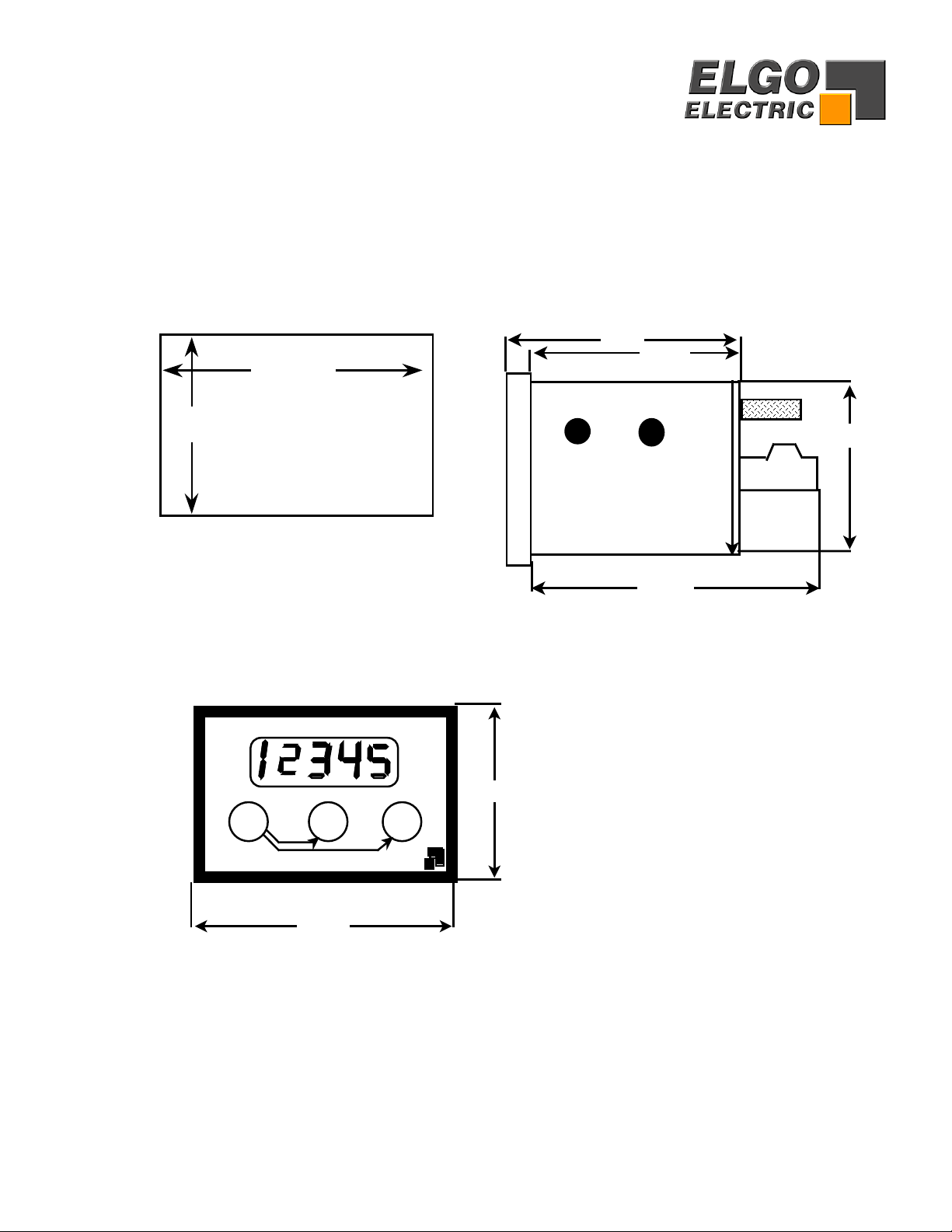
8. Dimensions
Cut out Side view
External dimensions
66 mm
44 mm 48mm
62mm
57mm
77mm
FRESET SET
ELECTRIC
ELGO
48mm
72mm
.
10

Z20
–
005- 024
–
9-X
MB 20.50.XX
,
X
MS 20.6X.XX
,
X
NG20.0
9. Type designation
Small Single axis display with Magnetic sensor input
Construction
005 = 0,01 Magnetic sensor interpolation circuit integrated
105 = Special 005 (Enable of parameter setting level by hardware link)
Supply voltage
024 = 24 V DC/ AC +/- 10%
Encoder input
9 = Magnetic sensor 0.01 mm resolution
Special Features
No options at the moment
Accessories
Magnetic tape :MB 20.50.25,0
Incremental Magnetic tape
Pole distance 5.0 mm
Length of tape
Magnetic Sensor MS 20.60 xx.x
Incremental magnetic sensor 0.01mm
60 = round connector
65 = angle connector
Length of sensor cable
Power supply 100mA 18Vdc din rail mounting version
11
10. Liability exclusion / Guarantee
We have checked the contents of this instruction manual carefully, to the best of our knowledge and belief for conformity
with the described hardware and software.
Nevertheless errors, mistakes or deviations can not be excluded, therefore we do not guarantee complete conformity.
Necessary corrections will be included in the subsequent editions.
We appreciate your ideas and improvement suggestions very much.
Reprint, duplication and translation, even in extracts, are only allowed with a written authorization by the company ELGO
Electric GmbH.
We constantly strive for improving our products, therefore we keep all rights reserved for any technical modifications
without any notice.
ELGO Electric does not assume any liability for possible errors or mistakes.
The guarantee periodis one calendar year(EC-Directive) fromthe date ofdelivery and includes the delivered unit with
all components. ELGO Electric GmbH will at its option replace or repair without charge defects at the unit or the included
parts, verifiable caused by faulty manufacturing and/or material in spite of proper handling and compliance to the
instruction manual.
Damages verifiably not caused by ELGO Electric GmbH and due to improper handling are excluded from any guarantee
e.g. by applying faulty voltage, diffusion of liquid into the interior of the engine, using force, scratching the surface,
chemical influences etc.!
Subject to modifications © 2004 ELGO Electric GmbH
12
Table of contents
Other ELGO Electric Measuring Instrument manuals


