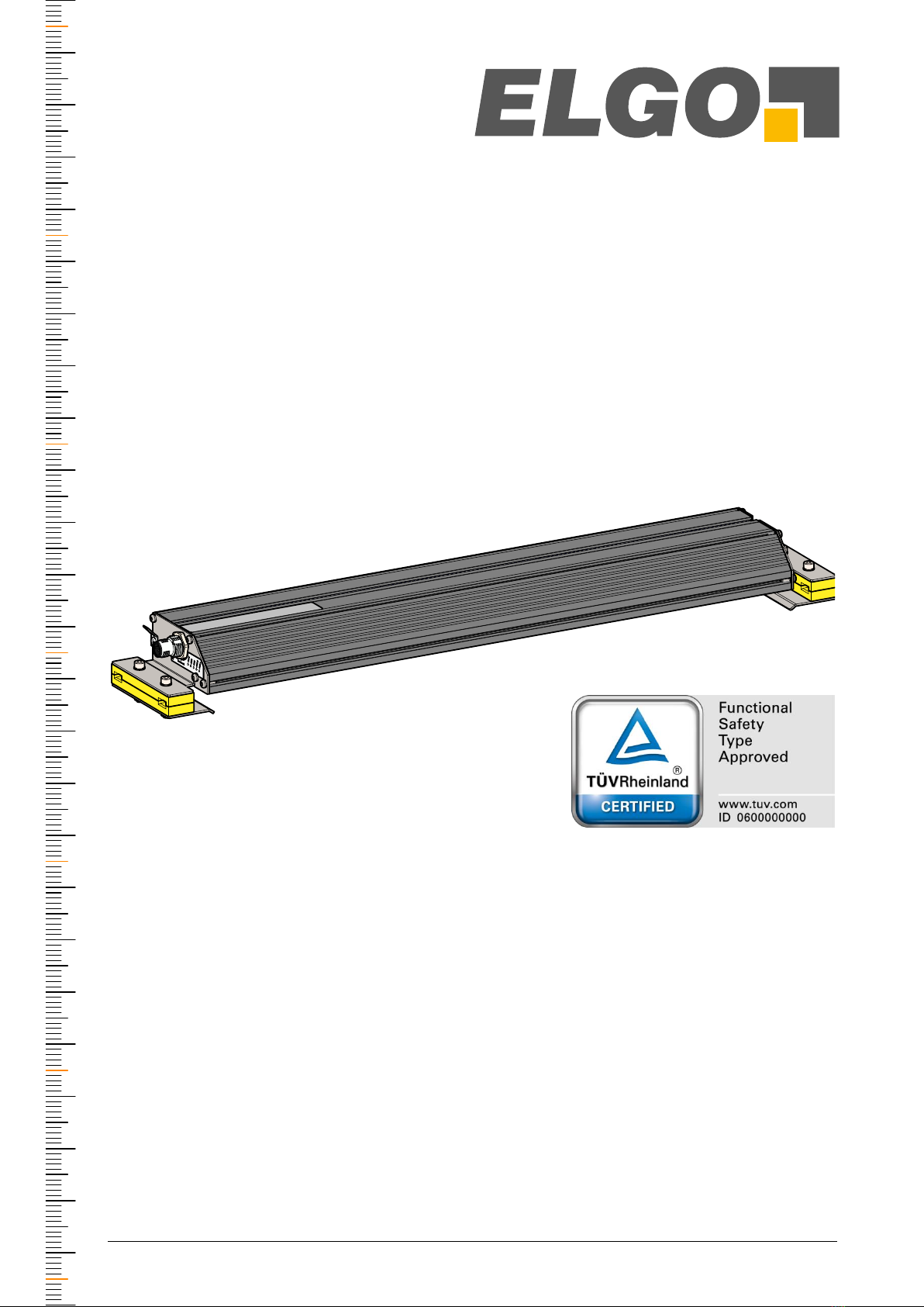
Elgo LIMAX44 RED User manual
- 1 -
Operating Manual
LIMAX44 RED
Safe Magnetic Absolute Shaft Information System
(Translation of the original operating manual)
Redundant sensor with integrated monitoring
TÜV certified according to SIL 3 in compliance with EN 61508
Absolute position always directly available –no reference journey even af-
ter long power failures
RS-485 Interface
Easy and flexible installation
Silent measuring principle
Immune to dirt, smoke and moisture
Door zone indication for up to 127 floors
Speeds up to 16 m/s
D-103836 / Rev. 0 / 2019-06-03
799000969
Registration No.:
968/FSP 1850.00/19


- 3 -
Contents
1Contents
1Contents ............................................................................................. 3
2General.............................................................................................. 5
2.1 Information Operating Manual .............................................................................5
2.2 Terms and Abbreviations......................................................................................5
2.3 Explanation of Symbols........................................................................................6
2.4 Referenced Documents ........................................................................................7
2.5 Statement of Warranties.......................................................................................7
2.6 Demounting and Disposal....................................................................................7
2.7 RoHS Conformity ................................................................................................7
3Safety ................................................................................................. 8
3.1 General Causes of Risk........................................................................................8
3.2 Personal Protective Equipment...............................................................................8
3.3 Conventional Use ...............................................................................................9
4Transport and Storage .................................................................... 10
4.1 Safety Instructions for Transport, Unpacking and Loading ........................................10
4.2 Handling of Packaging Material ..........................................................................10
4.3 Inspection of Transport ......................................................................................10
4.4 Storage ...........................................................................................................10
5Product Features .............................................................................. 11
6Technical Data ................................................................................. 14
6.1 Identification ....................................................................................................14
6.2 Safety Parameters .............................................................................................14
6.3 Technical Data Magnetic Tape and Presence Detector ............................................14
6.4 Dimensions Sensor............................................................................................16
6.5 Technical Data Sensor .......................................................................................18
6.6 Technical Data Magnetic Tape............................................................................19
7Type Designation ............................................................................. 21
7.1 Available Versions.............................................................................................21
8Installation and First Start-Up......................................................... 22
8.1 Operating Area ................................................................................................22
8.2 General Information..........................................................................................23
8.3 Mounting of the Magnetic Tape ..........................................................................23
8.4 Mounting of the Magnetic Tape Presence Detector .................................................26
8.5 Mounting of the Sensor......................................................................................27
8.6 Installation Procedure ........................................................................................29
9Design and Functions ...................................................................... 37
9.1 Sensor Design ..................................................................................................37

- 4 -
Contents
9.2 Operating Modes .............................................................................................39
9.3 LED Signals......................................................................................................39
9.4 Door Zone Indication ........................................................................................42
9.5 Connections and Interfaces ................................................................................42
10 Requirements for Evaluation Unit ................................................... 51
10.1 Hardware Requirements.....................................................................................51
10.2 Software Requirements.......................................................................................51
11 Accessories....................................................................................... 52
11.1 Mounting Kit Magnetic Tape (only semi-guided variant) ..........................................52
11.2 Mounting Aid Sensor .........................................................................................53
11.3 Spare Material Sensor .......................................................................................53
11.4 Connection Cable.............................................................................................53
12 Disturbances .................................................................................... 54
12.1 Error in Position Determination............................................................................54
12.2 Non-severe Errors .............................................................................................54
12.3 Severe Errors....................................................................................................55
12.4 Informative Errors (not Safety-Relevant).................................................................55
12.5 Fault Clearance................................................................................................56
12.6 Possible Errors and their Clearance......................................................................57
12.7 Re-start after Fault Clearance..............................................................................59
13 Maintenance .................................................................................... 60
14 Cleaning........................................................................................... 60
15 Index ................................................................................................ 63

- 5 -
General
2General
2.1 Information Operating Manual
This manual contains important information regarding the handling of the device.
For your own safety and operational safety, please observe all safety warnings and instructions.
Precondition for safe operation is the compliance with the specified safety and handling instructions.
Moreover, the existing local accident prevention regulations and the general safety rules at the site of operation
have to be observed.
Please read the operating manual carefully before starting to work with the device!
It is part of the product and should be kept close to the device and accessible for the staff at any time. The illus-
trations in the manual are for better demonstration of the facts. They are not necessarily to scale and can slightly
differ from the actual design.
2.2 Terms and Abbreviations
Abbreviation/
Term
Explanation
Verified position
See safe position data
CPU
Central Processing Unit
CRC
Cyclic Redundancy Check
EEPROM
Electrically Erasable Programmable Read-Only Memory (is used as non-volatile
data memory)
FS
Functional Safety
LSB
Least Significant Bit
Motorola format
When transmitting a value, the most significant byte is transmitted first. For a 32-bit
value it is for example bit 24 … bit 31
MSB
Most Significant Bit
MW
Mounting angle
RAM
Random Access Memory (main memory)
ROM
Read-Only Memory (program memory)
S-RMS
Mounting kit for rail mounting of the magnetic tape for safe sensors
(Safe Rail Mounting Set), can be used for the semi-guided variant.
Safe evaluation unit
Device that receives the safe position data of the sensor and cuts the safety circuit
in case of a disturbance. A safe position controller can fulfil the function of a safe
evaluation unit.
Safe position data
This position information may be used for safety functions.
Unsafe position data
Position information that may not be used for safety function due to missing redun-
dancy.
Safe state
In this mode the danger for passenger and environment is minimized. In the eleva-
tor industry, safe state means that the safety circuit of the elevator is opened and
the cabin is stopped.
Since LIMAX44 RED has no direct connection, it has to be connected to the safety
circuit via the safe evaluation unit.

- 6 -
General
2.3 Explanation of Symbols
Special notes in this manual are characterized by symbols.
The notes are introduced by signal words which express the magnitude of danger.
Please follow this advice and act carefully in order to avoid accidents and damage and injuries.
Warning notes:
DANGER!
This symbol in connection with the signal word “Danger” indicates an
immediate danger for the life and health of persons.
Failure to heed these instructions can result in serious damage to
health and even fatal injury.
WARNING!
This symbol in connection with the word „Warning” means a possibly
impending danger for the life and health of persons.
Failure to heed these instructions can result in serious damage to
health and even fatal injury.
CAUTION!
This symbol in connection with the signal word “Caution” indicates a
possibly dangerous situation. Failure to heed these instructions can
lead to minor injuries or damage of property.
Special safety instructions:
DANGER!
This symbol in connection with the signal word “Danger” indicates an
immediate danger for the life and health of persons due to voltage.
Failure to heed these instructions can result in serious damage to
health and even fatal injury. The operations may only be carried out by
a professional electrician.
Tips and recommendations:
NOTE!
…points out useful tips and recommendations as well as information
for an efficient and trouble-free operation.
References:
(1.2) Marks a reference to chapter 1.2 of this manual.
(DOC 3.4) Marks a reference to chapter 3.4 of the document DOC.

- 7 -
General
2.4 Referenced Documents
Designation
Type
Article. No.
Description
Download URL
LIMAX S-RMS-WH
Mounting Instructions
799 000 670
Magnetic tape installation kit with tape detection and tension weight for high rise ele-
vators
https://support.elgo.li/man/D-103858
LIMAX S-RMS-H
Mounting Instructions
799 000 971
Magnetic tape installation kit with tape detection and tension spring for high rise eleva-
tors
https://support.elgo.li/man/D-103932
LIMAX44 RED
Operating Manual
799 000 968
Original Operating Manual (German)
https://support.elgo.li/man/D-101872
2.5 Statement of Warranties
The statement of warranties is enclosed separately in the sales documents.
Guarantee
The producer guarantees the functional capability of the process engineering and the selected parameters. The
period of warranty is one year and begins with the date of delivery.
2.6 Demounting and Disposal
Unless acceptance and disposal of returned goods are agreed upon, demount the device considering the safety
instructions of this manual and dispose it with respect to the environment.
Before demounting:
Disconnect the power supply and secure against re-start. Then disconnect the supply lines physically and dis-
charge remaining energy. Remove operational supplies and other material.
Disposal:
Recycle the decomposed elements:
Metal components in scrap metal
Electronic components in electronic scrap
Recycle plastic components
Dispose the remaining components according to their material consistence
CAUTION!
Wrong disposal causes environmental damages!
Electronic scrap, electronic components, lubricants and other auxiliary
materials are subject to special refuse and can only be disposed by
authorized specialists!
Local authorities and waste management facilities provide information about environmentally sound disposal.
2.7 RoHS Conformity
LIMAX44 RED complies to the EU Directive on the restriction of the use of certain hazardous substances in elec-
trical and electronic equipment (RoHS) 2011/65/EU and its amendment from EU Directive 2017/2102 of 15
November 2017.
- 8 -
Safety
3Safety
CAUTION!
Please read the operating manual carefully, before using the device!
Observe the installation instructions!
Only start up the device if you have understood the operating manual.
The operating company is obliged to take appropriate safety measure.
The initial operation may only be performed by qualified and trained
staff.
Selection and installation of the devices as well as their embedding into
the controlling system require qualified knowledge of the applicable
laws and normative requirements on the part of the machine manufac-
turer.
3.1 General Causes of Risk
This chapter gives an overview of all important safety aspects to guarantee an optimal protection of employees
and a safe and trouble-free operation.
Non-observance of the instructions mentioned in this operating manual can result in hazardous situations.
3.2 Personal Protective Equipment
Employees have to wear protective clothing during the installation of the device to minimize danger of health.
Therefore:
Change into protective clothing before performing the works and wear them throughout the process.
Additionally observe the labels regarding protective clothing in the operating area.
Protective clothing:
PROTECTIVE CLOTHING
… is close-fitting working clothing with light tear strength, tight sleeves
and without distant parts. It serves preliminarily for protection against
being gripped by flexible machine parts.
Do not wear rings, necklaces or other jewellery.
PROTECTIVE GLOVES
…for protecting the hands against abrasion, wear and other injury of
the skin.
PROTECTIVE HELMET
…for protection against injuries of the head.
- 9 -
Safety
3.3 Conventional Use
The product described in this manual was developed to execute safety-related functions as a part of an entire
assembly or machine. It is the responsibility of the manufacturer of a machine or installation to ensure the prop-
er functioning of the system. The ELGO-device is only conceived for the conventional use described in this man-
ual.
The LIMAX44 RED - ELGO- length measuring system only serves to measure
lengths.
CAUTION!
Danger through non-conventional use!
Non-intended use and non-observance of this operating manual can
lead to dangerous situations.
Therefore:
Only use the device as described
Strictly follow the instructions of this manual
Avoid in particular:
Remodelling, refitting or changing of the construction or single
components with the intention to alter the functionality or
scope of the device.
Claims resulting from damages due to non-conventional use are not possible.
Only the operator is liable for damages caused by non-conventional use.

- 10 -
Transport and Storage
4Transport and Storage
4.1 Safety Instructions for Transport, Unpacking and Loading
CAUTION!
Transport the package (box, palette etc.) professionally.
Do not throw, hit or fold it.
4.2 Handling of Packaging Material
Notes for proper disposal: 2.6
4.3 Inspection of Transport
Check the delivery immediately after the receipt for completeness and transport damage.
In case of externally recognizable transport damages:
Do not accept the delivery or only accept under reserve.
Note the extent of damages on the transportation documents or delivery note.
File complaint immediately.
NOTE!
Claim any damage immediately after recognizing it. The claims for
damage must be filed in the lawful reclaim periods.
4.4 Storage
Store the device only under the following conditions:
Do not store outside
Keep dry and dust-free
Do not expose to aggressive media
Protect from direct sun light
Avoid mechanical shocks
Storage temperature (6 Technical Data) needs to be observed
Relative humidity (6 Technical Data) must not be exceeded
Inspect packages regularly if stored for an extensive period of time (>3 months)

- 11 -
Product Features
5Product Features
LIMAX44 RED is an absolute shaft information system which is used for the positioning of elevator cabins. It is
available in two different versions. In the unguided version, the measuring system consists of two components:
Magnetic tape and sensor. The semi-guided version requires an additional presence detector to monitor the
correct tape position.
The tape carries the unique position information as a magnetic code. In the unguided version, it is glued directly
onto the guide rail of the elevator. In the semi-guided version, it is mounted freely suspended in the shaft and is
guided along the sensor with a plastic guiding rail. The measurement is always contact free. The guiding only
serves to keep the tape within a defined distance from the sensor.
The sensor reads the magnetic code from the tape and then provides the evaluation unit connected downstream
with the position information.
The presence detector makes sure that the magnetic tape is in the intended position and remains there –after
all, various safety functions depend on the position derived from the tape.
In the case of unguided installation, this monitoring can be omitted, as it can be assumed that the magnetic
tape does not shift in its position.
According to EN 81-20/50 and previously EN 81-1/2 the use of programmable electronic systems in safety-
relevant applications for lifts (PESSRAL) is allowed. LIMAX44 RED is designed and certified for those applications.
The sensor is designed to be used as a safe sensor together with a safe evaluation unit (like for example in
ELGO´s LIMAX44 Safe) or directly with a safe controller unit. Together, the entire system is able to fulfil the safe-
ty functions in the elevator according to EN 81-20 and EN 81-21. The product is compatible to the previous
norm EN 81-1/2 and may be used as modernization solution or as measuring range extension in existing instal-
lations. Fig. 1 shows the use in the two possible areas of operation as unguided variant, Fig. 2 as semi-guided
variant.
The magnetic measuring principle is distinguished by its extremely high robustness. Dust, dirt and moisture do
not affect the measurement in any way. Furthermore, as smoke and increased temperatures do not have any
impact on the measurement, LIMAX44 RED is especially suitable for firemen’s lifts. Thanks to its material compo-
sition, the tape itself is resistant enough to the rough conditions during the installation and operation of eleva-
tors.
Another advantage of the system is in its easy and flexible mounting. The installation itself can be carried out by
an expert in just a few minutes. Depending on the space available, the system can be installed almost anywhere
in the shaft. Since it requires little space, LIMAX44 RED is also suitable without restrictions for retrofitting and
modernizations.
The LIMAX44 RED is able to cover lifting heights of up to 786 meters and speeds up to 16 m/s.
Overview of features:
Robust measuring principle for rough conditions
Easy and flexible mounting
High accuracy and repeatability
No slip
Absolute position always directly available –no reference journey even after long power failures
Compatible with many established position controllers with absolute encoder interface.
High speeds possible

- 12 -
Product Features
Fig. 1: LIMAX44 RED as unguided variant in combination with a safe controller (left) or in combination with the safe evalua-
tion unit Safe Box as the complete system LIMAX44 Safe (right)
communication,
power supply
Usage as stand-alone sensor Usage in the complete system LIMAX44 Safe
comm.,
PWR
system boundary electric interfaces
safe elevator
control
magnetic tape
non-safe elevator
control
safety gear trigger
communication,
power supply
safe evaluation unit
sensor head
sensor head
magnetic tape

- 13 -
Product Features
Fig. 2: LIMAX44 RED as semi-guided variant in combination with a safe controller (left) or in combination with the safe eval-
uation unit Safe Box as the complete system LIMAX44 Safe (right)
communication,
power supply
Usage in the complete system LIMAX44 Safe
safety circuit
comm.,
PWR
system boundary electric interfaces
safe elevator
control
magnetic tape
presence detector
for magnetic tape
non-safe elevator
control
safety gear trigger
safety circuit
communication,
power supply
safe evaluation unit
sensor head
Usage as stand-alone sensor
- 14 -
Technical Data
6Technical Data
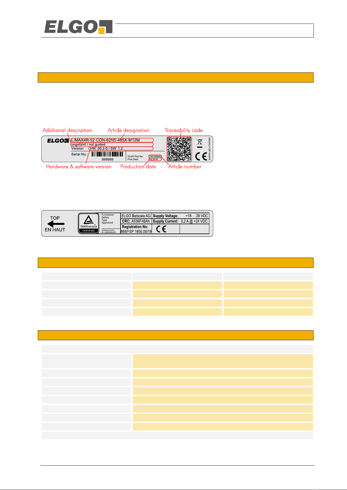
6.1 Identification
The type label serves for the identification of the unit. It is located on the housing of the sensor and gives the
exact type designation (=order reference, see type designation, chapter 7) with the corresponding part number.
Furthermore, the type label contains a unique, traceable device number, the production date as well as the
hardware and software versions.
When corresponding with ELGO always indicate this data.
Fig. 3: Type label for identification of the sensor
Also, there is an info label on the sensor that gives the following additional information on the sensor: manufac-
turer, supply voltage, power consumption, CRC check sum of the software and the registration number of the
certificate.
Fig. 4: Info label with additional information
6.2 Safety Parameters
Designation
Value
Remark
Safety Integrity Level
SIL 3
PFH [1/h]
2.2 E-9
2.2 % of SIL 3
PFDavg
1.9 E-4
19 % of SIL 3
Proof Test Interval T1
20 years
6.3 Technical Data Magnetic Tape and Presence Detector
ZS 256-11ZR-1519
Regulations:
IEC/EN 60947-5-1
BG-GS-ET-15
Operating temperature:
-30 °C … +80 °C
Dimensions (without cable):
L x B x H = 58 x 50.5 x 31 mm
Protection class:
IP67
Usage category:
AC-15; DC-13
Ie/Ue
4 A / 230 VAC; 1 A / 24 VDC
Short-circuit protection:
6 A gL/gG D-fuse
Terminal cross-section:
min. 1.5 mm²; max. 2.5 mm² (incl. cable end sleeves)

- 15 -
Technical Data
ZS 236-02ZR-1519
Regulations:
IEC/EN 60947-5-1
BG-GS-ET-15
Operating temperature:
-30 °C … +80 °C
Dimensions (without cable):
L x B x H = 30 x 58.5 x 30 mm
Protection class:
IP67
Usage category:
AC-15; DC-13
Ie/Ue
4 A / 230 VAC; 1 A / 24 VDC
Short-circuit protection:
6 A gL/gG D-fuse
Terminal cross-section:
min. 1.5 mm²; max. 2.5 mm² (incl. cable end sleeves)
- 16 -
Technical Data
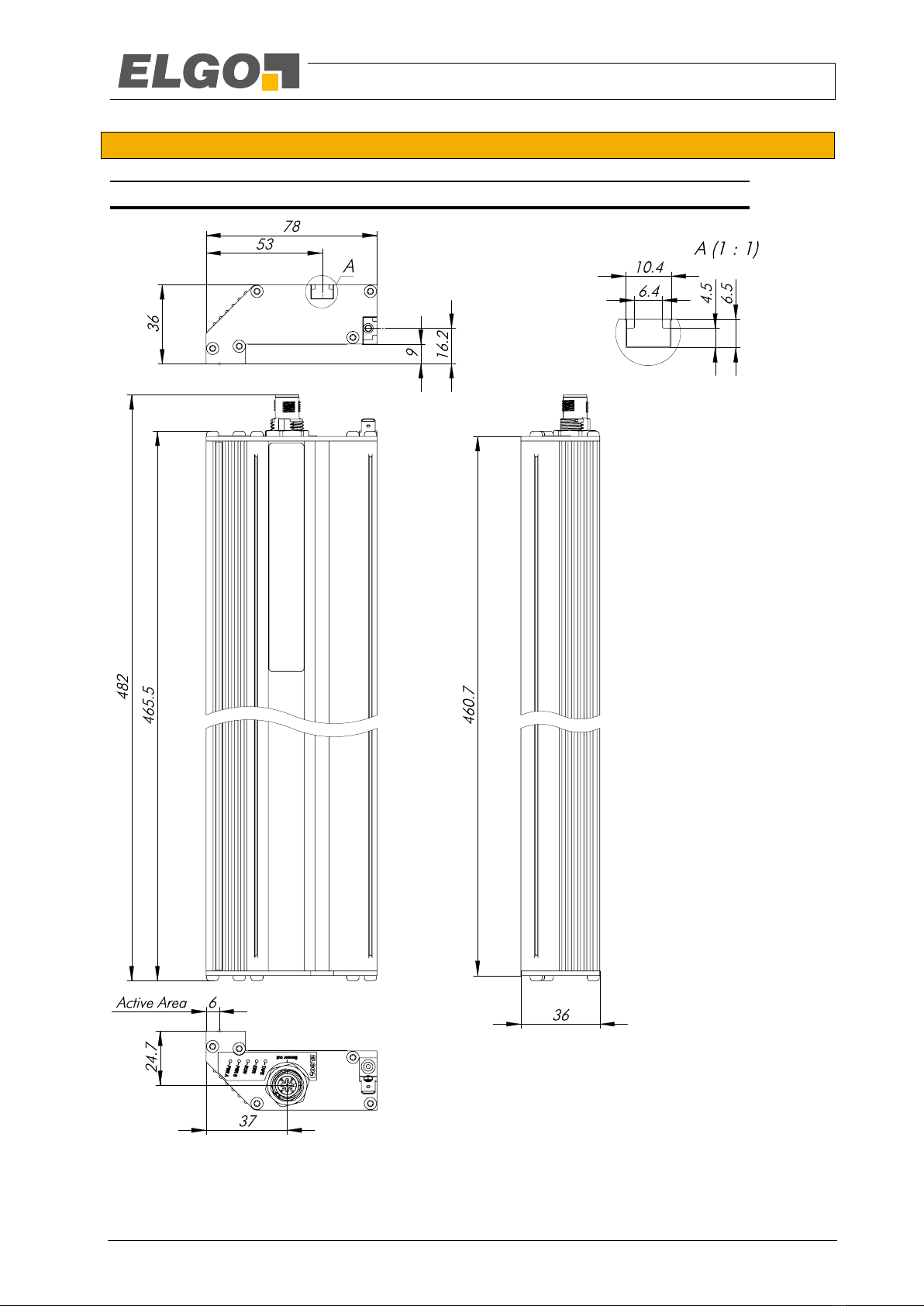
6.4 Dimensions Sensor
6.4.1 Unguided variant
Fig. 5: Dimensions LIMAX44 RED variant unguided
- 17 -
Technical Data
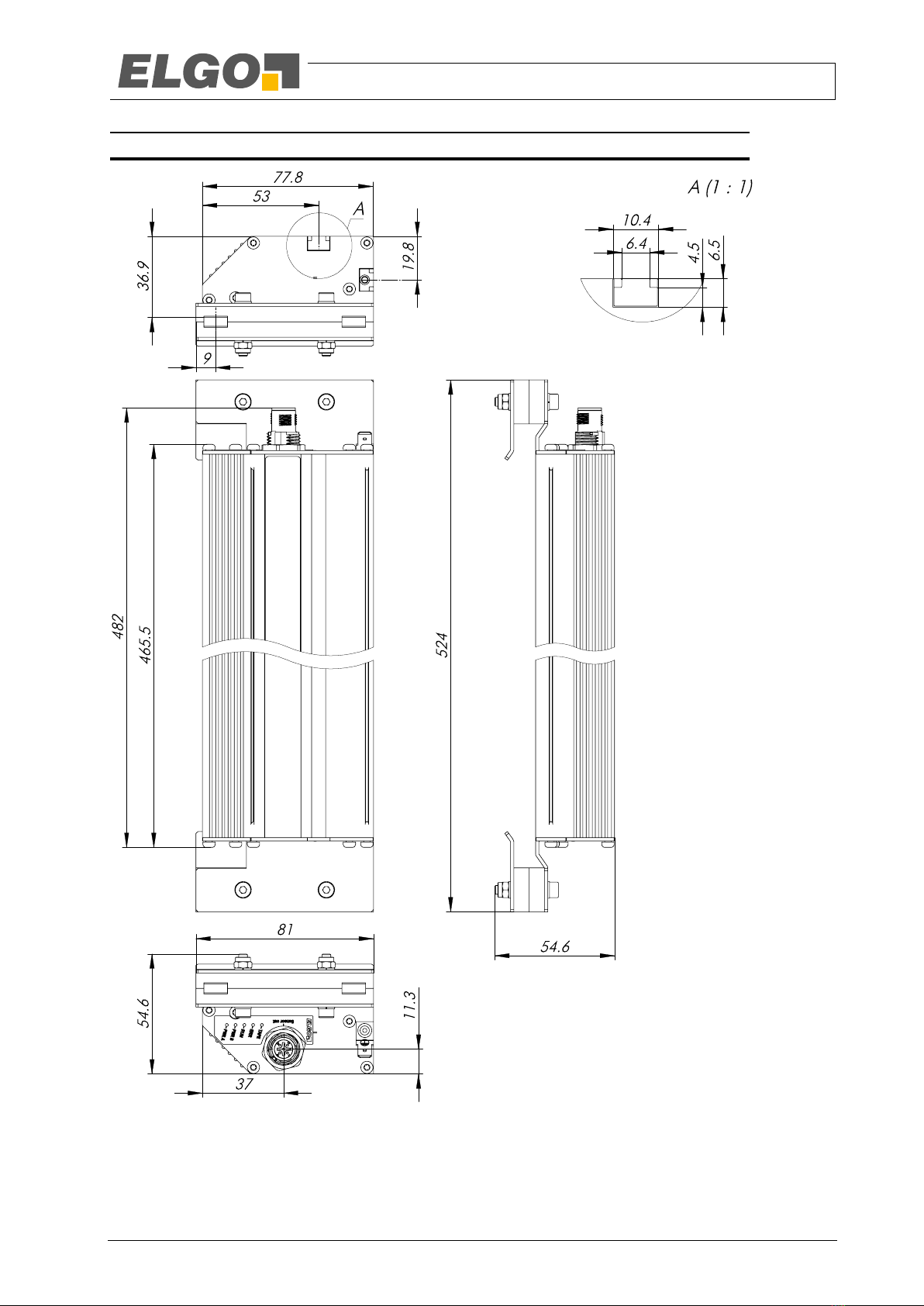
6.4.2 Semi-guided variant
Fig. 6: Dimensions LIMAX44 RED variant semi-guided

- 18 -
Technical Data
6.5 Technical Data Sensor
LIMAX44 RED (Standard version)
Mechanical Data
Measuring principle:
absolute
Measurement:
linear
Maximum measuring length
786 m
Speed:
max. 16 m/s
Resolution:
7 Type Designation
Repeat accuracy:
+/- 1 Increment
System accuracy at 20°C:
+/- (1000 µm + 100 µm x L[m])
L = measuring length in meter
Distance from sensor to magnetic
tape
4.5 mm (semi-guided variant)
max. 8 mm (unguided variant)
Dimensions (without cable):
semi-guided variant:
L x W x H = 524 x 81 x 55 mm
unguided variant:
L x W x H = 482 x 78 x 36 mm
Housing material:
aluminium
Connection:
circular plug 5-pole M12
(more options as cable 11.4 Connection Cable)
Weight without cable:
approx. 1030 g (semi-guided) / 820 g (unguided)
Magnetic tape
Necessary type:
semi-guided variant:
AB20-80120-10-1-R-D-1516-BK80
unguided variant:
AB20-120-20-1-R1-C-16A-4943F (0 m …285 m)
AB20-120-20-1-R1-C-16B-4943F (285 m …570 m)
AB20-120-20-1-R1-C-16C-4943F (570 m …786 m)
Conditions
Storage temperature:
-20 °C … +85 °C
Operation temperature:
-10 °C … +70 °C
Humidity:
max. 95 %, non-condensing
Protection class:
IP54 (according to EN 60529)
Operation height:
max. 2000 absolute altitude
EMC transient emission/immunity:
according to EN 12015 / EN 12016
Vibration/shock resistance:
according to EN 60068-2-6 / EN 60068-2-27
Electrical Data
Supply voltage:
+ 18 … 29 VDC (stabilized) in dual-channel operation (9.2.1)
+ 10 … 18 VDC (stabilized) in single-channel operation (9.2.2)
You must use a power supply with Safety Extra Low Voltage (SELV) or
Protective Extra Low Voltage (PELV).
Residual ripple:
< 100 mVpp
Reverse voltage protection:
integrated
Power input:
max. 200 mA @ 24 VDC without loading the output for the door zone
indication
Interfaces:
RS-485
Protection of the outputs/ interfac-
es:
RS-485 output: short-circuit-proof
output door zone indication: short-circuit-proof to GND, but not to

- 19 -
Technical Data
+24V
Cable length:
according to EIA RS-485 specifications
Maximum operating time1)
20 years
1) After this time the device must be replaced.
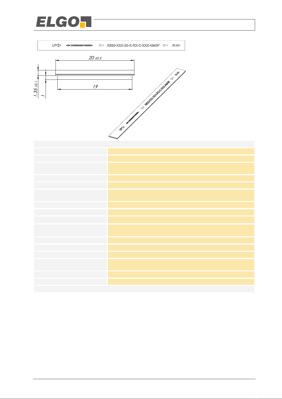
6.6 Technical Data Magnetic Tape
The magnetic tape consists of two components:
The actual magnetic tape which carries the position information
A mechanical stainless steel back iron
Magnetic Tape AB20-120-10-1-R-D-16-BK80 (for semi-guided variant)
Coding:
absolute, ELGO 16 Bit
Basic pole pitch:
12 mm (± 0.05 mm)
Maximum tape length:
up to 300 m per role available, other lengths up to 786 m on request
Maximum length error:
± 200 µm/m
Operation temperature:
-20 °C … +70 °C
Storage temperature:
short-run: -40 °C … +85 °C
medium-run: -20 °C … +70 °C
Relative humidity:
max. 95 %, non-condensing
Dimensions:
B / B1 x H = 10 mm (± 0.1) / 8 mm (± 0.2) x 1.35 mm (± 0.1)
Linear expansion coefficient:
16 x 10-6 1/K
Linear thermal expansion:
∆L[m] = L[m] x [1/K] x ∆[K]
(L = tape length in meter, ∆= relative change in temperature)
Bend radius:
min. 100 mm
Weight of magnetic tape
ca. 52 g/m
Tape imprint
ELGO Standard, colour black, front size ≥5 mm
External magnet:
External magnetic fields shall not exceed 64 mT (640 Oe; 52 kA/m),
otherwise the magnetic coding will be damaged or destroyed.
Protection:
Back iron stainless steel (1.4310)
- 20 -
Technical Data
Magnetic Tape AB20-120-20-1-R1-C-16x-4943F (for unguided variant)
Coding:
absolute, ELGO 16 Bit
Basic pole pitch:
12 mm (± 0.05 mm)
Maximum tape length:
300 m per role / tape section
longer tapes must be composed of several segments of 285 m each.
Maximum length error:
± 200 µm/m
Operation temperature:
-10 °C … +70 °C
Storage temperature:
short-run: -10 °C … +60 °C
medium-run: +50 °C at 50% RH
Relative humidity:
max. 95 %, non-condensing
Dimensions:
B x H = 20 mm (± 0.1) x 2.45 mm (± 0.1)
Linear expansion coefficient:
11 x 10-6 1/K
Linear thermal expansion:
∆L[m] = L[m] x [1/K] x ∆[K]
(L = tape length in meter, ∆= relative change in temperature)
Bend radius:
min. 50 mm
Weight of magnetic tape
ca. 140 g/m (incl. adhesive tape and carrier)
Tape imprint
ELGO Standard, colour black, front size ≥6 mm
External magnet:
External magnetic fields shall not exceed 64 mT (640 Oe; 52 kA/m),
otherwise the magnetic coding will be damaged or destroyed.
Protection:
Back iron stainless steel (1.1248)
Adhesive tape:
3M 4943F
Table of contents
Other Elgo Industrial Equipment manuals


