DEPURECO AIRWELD Instructions for use

1
ner.alec acuumv eth fo ecnaentnmai dam
eus nda esaf orf lesabenispndi is nedtaionc ereh sonuctirstni eth fo
ed.ilsupp tsenattachm ertho eth nda luanma this yllfureca dare ot
sendmmocre ocrepuDe neralec acuumv eth fo trpa largetni na msorf luanma hisT
egledwnoK
rev. A del 80 nov- -20 61

2
1.
GENERAL
INFORMATION....................................................................................................................... 4
1.1. PURPOSE OF THE
MANUAL................................................................................................................................................4
1.2.
KEY
OF SYMBOLS
USED........................................................................................................................................................ 5
1.3.
DEFINITION
OF THE OPERATORS
QUALIFICATIONS
..........................................................................................................
6
1.4. GLOSSARY
..............................................................................................................................................................................
6
1.5.
ATTACHED DOCUMENTATION
..............................................................................................................................................
7
1.6.
W
ARRANTY
..............................................................................................................................................................................
7
2.
SAFETY INFORMATION
.......................................................................................................................... 8
2.1.
RESIDUAL
RISKS....................................................................................................................................................................8
2.2. GENERALSAFETY
W
ARNINGS
.............................................................................................................................................8
2.3. SAFETYWARNINGSFOR
HANDLING, ASSEMBLY
AND
INST
ALLA
TION
.............................................................................
8
2.4. SAFETYWARNINGSFOR INTENDEDUSE
............................................................................................................................
9
2.5. SAFETYWARNINGSFOR
ADJUSTMENT/MAINTENANCE
...................................................................................................
9
2.6. SAFETYWARNINGSFOR
ENVIRONMENTAL IMPACT
..........................................................................................................
10
2.7. SAFETYSIGNS PLACED ON THE
MACHINE
.........................................................................................................................
10
3.
HANDLING,
ASSEMBLYAND
INSTALLATION INFORMATION
............................................................. 11
3.1. DIRECTIONS FOR
HANDLING
THE
PACKAGE
......................................................................................................................
11
3.2. DIRECTIONS FOR
MACHINE ASSEMBLY
.............................................................................................................................12
3.3.
MACHINE HANDLING
MODE..................................................................................................................................................13
3.4.
MACHINE INSTALLATION
MODE
..........................................................................................................................................13
3.5.
ELECTRICAL
CONNECTION MODE
......................................................................................................................................15
3.6. METHODS FOR
INSTALLING
OPTIONALS............................................................................................................................15
4.
TECHNICAL INFORMATION
.................................................................................................................. 16
4.1.
MANUFACTURER
AND
MACHINE IDENTIFICATION
.............................................................................................................16
4.1.1.
Facsimile
of the
Declaration
of Conformity
.....................................................................................................................
17
4.1.2. Machine identification plate
.............................................................................................................................................18
4.2.
MACHINE
DESCRIPTION
........................................................................................................................................................
19
4.3. OPERATING CYCLEDESCRIPTION
.......................................................................................................................................
19
4.4.
TECHNICAL DATA
...................................................................................................................................................................
20
4.4.1.
Performance....................................................................................................................................................................... 20
4.4.2. Diagram and electrical values
...........................................................................................................................................
21
4.4.3. Size of air inlet
....................................................................................................................................................................
23
4.4.4. Size of air outlet
.................................................................................................................................................................
23
4.4.5. Filter
...................................................................................................................................................................................
24
4.5. SAFETYDEVICEDESCRIPTION
.............................................................................................................................................
24
4.6. DESCRIPTION OF PERIMETER
AREAS
..................................................................................................................................
25
5.
INFORMATION
ON
USE
.......................................................................................................................... 27
5.1. INTENDEDUSE/IMPROPER USE
...........................................................................................................................................
27
5.2. START-UP AND
STOP
..............................................................................................................................................................
27
6.
INFORMATION
ON
ADJUSTMENTS.......................................................................................................
28
6.1. RECOMMENDATIONS FOR ADJUSTMENTS
.........................................................................................................................
28
6.2. FLOW RATE
REGULATION......................................................................................................................................................
28
7.
MAINTENANCE INFORMATION
............................................................................................................. 29
7.1. RECOMMENDATIONS FOR
MAINTENANCE
INTERVENTIONS
............................................................................................
29
7.2.
TABLE
OF SCHEDULED
MAINTENANCE INTERVALS
..........................................................................................................
29
7.3.
CLEANING
...............................................................................................................................................................................
29
8.
INFORMATION
ON
TROUBLESHOOTING
............................................................................................. 30

3
9.
INFORMATION
ON
REPLACEMENTS
.................................................................................................... 30
9.1. RECOMMENDATIONSFOR REPLACEMENT
INTERVENTIONS............................................................................................ 03
9.2. LISTOF
REPLACEABLE
COMPONENTS
...............................................................................................................................
13
9.2.1.
Standard
............................................................................................................................................................................
13
9.2.2.
Optional..............................................................................................................................................................................
13
9.3. SCRAPPING ANDDECOMMISSIONING
...............................................................................................................................
53

4
1. GENERAL INFORMATION
1.1. PURPOSE OF
THE
MANUAL
The
manual
has the
purpose
of providing the
machine
installer,
operator
and
maintenance technician, the
instructions
for use,
prevention
and
reduction
of risks during
man-machine interaction.
OPERATOR CHAPTERS OF
THE MANUAL
THAT MUST BE KNOWN
•
General information
•
Safety
information
INSTALLER
SECOND
MAINTENANCE
TECHNICIAN
•
Handling,
assembly
and installation
information
•
Technical
information
•
Information on
replacements
•
General information
•
Safety
information
•
Information on
use
•
General information
•
Safety
information
•
Handling,
assembly
and installation
information
•
Information on
use
•
Information on
adjustments
•
Maintenance information
•
Information on
troubleshooting
•
Information on
replacements
The information was
drawn-up
by the
Manufacturer
in its original
language
(Italian) and it can also be
made
available in other
languages,
in order to meet the legal
and/or business requirements.
The
documentation
must be kept by the
person
in
charge,
in a
suitable place,
so that it is always available for
consultation
in the best state of
preservation.
If
lost or worn,
request replacement documentation
directly from
the
Manufacturer.
Consult the table of
contents
to easily locate the specific topics of
interest.
Some
information may not fully
correspond
to the effective
configuration
of the delivered
machine.
Any
additional
information that may be
inserted,
will
not affect legibility and
does
not
jeopardise
the safety
level.
The
Manufacturerreserves
the right to
change
the information without being
obliged
to notify it in
advance,
as
long as such
changes
do not alter the safety
level.
Any report by the
recipients
may be an
important contribution
for the
improvement
of
after-sales services
that
the
Manufacturer intends
offering its
customers.
Some symbols,
the
meanings
of which are
described
below, are
used
to highlight
some
text or
indicate
significantly
important specifications.

5
1.2.
KEY
OF SYMBOLS USED
SYMBOL DESCRIPTION
Danger -
Attention
The symbol
indicates situations
of
serious danger
that,
if
neglected,
may place the
health
and
safety of
people seriously
at
risk.
Danger -
Attention
The symbol
indicates situations
of
serious danger
that,
if
neglected,
may
cause
fires
and
place
the health and safety of
people seriously
at
risk.
Explosion hazard
This symbol
indicates situations
of
serious danger
that,
if
neglected,
may
cause explosions
and
seriously
place the health and safety of
people
at
risk.
Caution -
W
arning
The symbol
indicates
the
need
to
adopt adequate behaviour
to avoid placing the health
and
safety of
people
at risk and not
cause economic
damages.
Important
The symbol
indicates
significantly
important technical
and
operational
information that must
not
be
neglected.
Use
protective gloves.
Use safety
footwear.
Use
protective
mask.
Use
acoustic protection.

6
1.3.
DEFINITION
OF
THE
OPERATORS QUALIFICATIONS
Some
terms that are frequently
used
within the
manual
are
described
in order to uniquely
determine their
meaning.
OPERATOR QUALIFICATION
DESCRIPTION
Personnel
who have
attended specialisation, educational
and
training
Qualified
personnel
Experienced maintenance
technician
courses
and have
experience concerning
the installation,
commissioning
and
maintenance
of the
plants.
Technician chosen
and
authorised
from
among those
having the
qualifications,
skills and information, to perform routine and
extraordinary maintenance
interventions.
1.4. GLOSSARY
DEFINITION DESCRIPTION
Set of
operations required
to
preserve
the functionality and efficiency
Maintenance
of the
machine. These operations
are
scheduled
by the
Manufacturer, who
defines
the
necessary
skills and
methods
of
intervention.
Circuit breaker switch Is a safety device able to interrupt the flow of electrical current in an
electrical
circuit of an electrical
system
in the event of
over-current.
Filter Is the main filtration
element,
that can be of sleeve or
cartridge type.

7
DEFINITION DESCRIPTION
Hood/Dome
A rigid
element
available in various
shapes
and sizes with the function of
receiving polluting
elements.
1.5.
ATTACHED
DOCUMENTATION
Below is a list of the
documents supplied
with the
machine
and not
present
inside this
manual.
•
EC
Declaration
of
conformity
•
Overall
drawing
and
exploded assembly drawing
1.6. WARRANTY
The warranty is
subject
to the
following general
conditions
:
•
the
packaging
must be
opened
and the installation
performed
by the
Manufacturer's
authorised and/or
enabled technicians;
•
the installed
machine commissioning
and positive test must be
done
in the
presence
and under
the
supervision
of the
Manufacturer's technicians
or of its
agent's;
the test report must be filled in.
•
the
machine
must be
used
within the limits
stated
in the
contract
and as
indicated
in the
technical and/or
business documentation.
•
maintenance
must be
performed
within the time and under the
conditions provided
by this
manual, using
original
spare
parts
DEPURECO S.r.l
. and
entrusting
the work to qualified
personnel.
The warranty
becomes
void in the event of:
•
failure to comply with the safety
standards;
•
removal or
tampering
with the control and safety
devices (guards, photocells, sensors,
micro
switches, etc.);
•
changes
to the safety
conditions established
by the
Manufacturer;
•
improper
use of the
machine;
•
use of the
machine
by
untrained and/or unauthorised personnel,
or
non-compliance
with the
operators'
skills, as
specified
in the
manual;
•
changes
or repairs
made
by the user without the
Manufacturer's
written
authorisation;
•
partial or total
non-compliance
with the instruction
manual;
•
power supply failures (electric power,
compressed
air,
etc.);
•
poor
maintenance;
•
use of non-original
spare parts;
•
extraordinary events
like floods, fires
(if
not
caused
by the
machines).
The warranty
does
not
cover
:
•
materials
such as: oils,
cartridges
for filters,
lubricating
grease.
•
parts
damaged
by bad or
improper
use, by
incorrect operator intervention,
by
unauthorised
repair
and
tampering performed
by the
customer
or by third party, or use of
spare
parts not
supplied
by
DEPURECO
S.r.l
.
Protect
Go months.24toupwarrantytheextendtoformtheinfill,www.depureco.comto program”pluswarranty“exclusivethejoiningbypurchasesyour

8
2.
SAFETY
INFORMATION
Carefully read the
instructions
in this manual and
those applied
directly on the
machine.
2.1.
RESIDUAL
RISKS
RESIDUAL
RISK DESCRIPTION
Voltage hazard
Maintenance operations performed
on live
machine
electrical parts entail
the
risk of
electrocution.
Rotating
elements
hazard
Maintenance operations performed
by inserting
hands
near the fan and with
the
machine powered,
entail the risk of cutting the
upper limbs.
Danger of
crushing
to
lower
limbs
Maintenance operations
that require tipping the
machine
over, carried
out
without the use of
personal protective devices, poses
the risk of
crushing
lower
limbs.
Dust inhalation danger
Maintenance operations performed
inside the
machine
entail the risk of
inhaling potentially
carcinogenic
dust.
Fire risk Routine
operations performeddespite
the prohibition
expressed
in
paragraph
"INTENDED
USE/IMPROPER
USE"
.
Risk of
explosion
Routine
operations performeddespite
the prohibition
expressed
in
paragraph
"INTENDED
USE/IMPROPER
USE"
.
2.2.
GENERAL SAFETY
WARNINGS
Personnel performing
any type of intervention
throughout
the
machine
life-span, must have
precise technical
skills,
special
abilities due to
acquired
and
recognised experience
in the specific
sector,
be trained on how to
use
the
necessary
work tools and
appropriate personal protective equipment,
with
reference
to the
applicable laws
and in force in the place of use of the
machine.
Lacking
these requirements
may
cause damage
to
people's
health and
safety.
Use the
personal protective equipment indicated
in the
manual.
2.3.
SAFETY
WARNINGSFOR
HANDLING,
ASSEMBLYAND
INST
ALLA
TION
Use
adequate
lifting
equipment
for
handling
and
adopt
all the safety
precautions designed
for activities
carried
out in the work
site.
Machines
fitted with
wheels
must be set up in safe
conditions
by
engaging
the
brakes
on the swivel
wheels.

9
2.4.
SAFETY
WARNINGSFOR
INTENDED
USE
The
machine
was
designed
to work within the limits
prescribed
and
indicated
in the
manual.
Using the
machine
to obtain
production
levels other than
those described
in this
manual,
shall be
regarded
as
“IMPROPER USE”
.
Carefully read the
instructions
in
paragraph
"INTENDED
USE/IMPROPER USE".
2.5.
SAFETY
WARNINGSFOR
ADJUSTMENT/MAINTENANCE
Perform routine
maintenance
as
provided
for in this
manual.
Disconnect
the
machine
from the electricity
sources
before any
maintenance intervention.
Use the main switch to interrupt power and
padlock
it before any
maintenance intervention.

10
2.6.
SAFETY
WARNINGSFOR
ENVIRONMENTAL
IMPACT
Do not
disperse
polluting material in the
environment.
Perform
disposal
in
compliance
with the relative laws in
force. Incorrect
cleaning
or not
replacing
the filters may
cause
the polluting
agent
to be
dispersed
in the
external
environment.
2.7.
SAFETY
SIGNS PLACEDON
THE
MACHINE
SYMBOL DESCRIPTION
Rotation direction of the
motor.
Turn the fan off and
disconnect
the power before
opening
the filter.
V
oltage
hazard.

11
3.
HANDLING,
ASSEMBLYAND
INSTALLATION
INFORMATION
3.1.
DIRECTIONS
FOR
HANDLING THE
PACKAGE
The
standard packaging
DEPURECO S.r.l.
does
not
guarantee protection against
rain,
storage areas
must be
covered
and not
humid.
When
handling materials,use suitable
lifting
devices
and adopt all of the
safety precautions
required for the worksite
activities,
also
consult
the
technical
data for the
packaging
described
in the
Packing List.
On the
platform.
MACHINE
MODEL
PACKAGING DIMENSIONS
(a) x (b) x (h)
WEIGHT
(KG)
AIRWELD
CARRIAGE
702 x 756 x
916
80
AIRWELD
WALL
702 x 756 x
916
80
Provide a delimited and
adequate
area, with level floor or
surface,
for
unloading
and
depositing
packs.
Itis always
advisable
to keep the
packs
horizontal during
handling
in order to avoid loosing stability
and/or them
overturning.

12
3.2.
DIRECTIONS
FOR
MACHINE
ASSEMBLY
Before
assembly,
visually
inspect
the material to make sure it was not
damaged during
transportation.
Ifthere are
signs
of
damage,
inform the
seller
within 10 days from
delivery
.
Before
proceeding
with
assembly,
read paragraph
“MACHINE INSTALLATION
METHODS”.
During
assembly,
installation and
maintenance,
the
screws
must be
tightened according
to the values
provided
in the
table.
The
tightening torques
must be
applied
slowly and
constantly
using a
torque
wrench. Said values must
be
decreased
by 10% when using impact
drivers.
The table refers to
class
4.8
screws.
DIAMETER
PER PITCH
SCREW SECTION
mm
2
SCREW TIGHTENING TORQUES
Nm
6 x
1
20
3,5
8 x
1,25
36
8
10 x
1,5
58
17
12 x
1,75
84
28
The table refers to
class
8.8
screws.
DIAMETER
PER PITCH
SCREW SECTION
mm
2
SCREW TIGHTENING
TORQUES
Nm
6 x
1
20
10,4
8 x
1,25
36
25
10 x
1,5
58
50
12 x
1,75
84
87

13
3.3.
MACHINE HANDLING
MODE
The
machine
is fitted with
wheels
for
moving.
The
machine
has a tube frame of
ergonomicshape suitable
for
handling.
3.4.
MACHINE INSTALLATION
MODE
Before
installation, check
that the overall
dimensions
required to perform work and
maintenance
are without
constraint. See
paragraph
"DESCRIPTION
OF
PERIMETER
AREAS".
Before
proceeding
with
installation,
make sure the wall is able to support the overall
load
of the
machine
and any
optional features. See
“Technical data - Weight” and
“Description of
perimeter
areas”.
Before starting the
machine
up,
engage
the brakes on the
wheels.

14
The
machine
must be installed in the
immediate
vicinity of utilities and
connected
by
articulated suction arm.
AIRWELD
AIRWELDWALL

15
3.5.
ELECTRICAL CONNECTION
MODE
Verify the correct power
supply
before making the
electrical
connections.
The
machine
is fitted with a circuit
breaker located
in an IP54
casing.
Make the
connections
by referring to
the
diagrams
in
paragraph
“TECHNICAL DATA/DIAGRAM
AND
ELECTRICAL
VALUES”.
The
machine
is fitted with a power cable with 4-pole
plug.
Start and stop the
machine
for a short time to verifythe
proper
rotation direction of the fan,
indicated
by the
arrow
on the
motor.
3.6.
METHODS
FOR
INSTALLING
OPTIONALS
Prior to any
installationprocedure,
read the
instructions provided
in the “RECOMMENDATIONS
FOR
MAINTENANCE INTERVENTIONS”
paragraph
carefully
.
To
replace
optional parts, see
paragraph
“LIST
OF
REPLACEABLE
PARTS”.
The following
optionals
can be
mounted
on the
machine:
•
articulated
extractor
arm;
•
polyester cartridge
filter;
•
aluminium-coated cartridge
filter;
•
teflon-coated cartridge
filter.

16
FILTER
4. TECHNICALINFORMATION
4.1.
MANUFACTURER
AND
MACHINE
IDENTIFICATION
The
manufacturer's
identification is
stated
on the identification plate and on the
declaration
of
conformity
.
The table
states
the
machine
function and the
models.
MACHINE
MODEL
CLEANGO
1,1
kW AIRWELD
WALL
1,1
kW AIRWELD1,1 kW
USA

17
4.1.1.
FACSIMILE
OF
THE DECLARATION
OF CONFORMITY
DECLARATION OF CONFORMITY
(for machines not included in Annex IV)
The Manufacturer
DEPURECO INDUSTRIAL VACUUMS S.r.l.- C.so Europa. 609 10088 Volpiano (TO) - ITALY
T
www.depureco.com - C.F. e Partita.Iva 02258610357
declares
under its own responsibility that the vacuum model
described in this manual
Year of construction:
Turin, ________________ The Legal Representative
(Marco DEVINCENTIS)
[original signed document]
2
0
Space for the application of the identification data label
To
roval.ppa s’manufacture
eht outhitw ,cleaner vacuum eht to made are esganhc if valid not is declaration ishT
S.r.l. DEPURECO at filed file nicalhtec in listed
are ,inehmac of gtestin and gmanufacturin ,ngdesi for used Standards edzarmoniH
EU/0/32014 Directive ilitybatipCom neticgElectroma and EC/426/200
DirectiveineshMac yb rovidedp uirementsqre safety essential eht hitw liespcom refers declatation isht hicwh

18
4.1.2.
MACHINE IDENTIFICATION
PLATE
The plate
indicates
the
Manufacturer's
data and the
technical references essential
for
proper
and safe
use.
IDENTIFICATION
PLATE

19
4.2.
MACHINE
DESCRIPTION
The
purpose
of the
machine
is to extract and filter welding fumes and metal
smoothing
dust
produced by
mechanical
industry
processing.
The polluting
elements
are
captured
and carried
towards
the filter
through
rigid or flexible
pipes connected to
the
hood.
4.3.
OPERATING CYCLE
DESCRIPTION
AIRWELD AIRWELD WALL
C
A
B
B
C A
STAGE DESCRIPTION
A The air
extracted through
the pipe is
conveyed
by the fan in the
body
.
B
The dusty air
passes through
the
cartridge
filter that
captures
the
dust.
C The clean air outlet is under the
machine.

20
AIRWELD
USA
AIRWELD
W
ALL
4.4.
TECHNICAL
DATA
4.4.1. PERFORMANCE
Power [HP/kW]
1,5/1,1
1,5/1,1
Power
supply voltage
3Ph [V]
400
400
Power
supply voltage
1Ph [V]
/
/
Consumption [A]
2,54
2,54
Frequency [Hz]
50/60
50/60
Motor
phase [Ph]
3
3
RPM
2846
2867
Type of
fan
PR-PRM
300
PR-PRM
300
Max flow rate
[m3/h]
1400
1400
Nominal min flow rate
[m3/h]
903
903
Sound
level
[db(A)]
72
72
Weight
[kg]
80
80
This manual suits for next models
3
Table of contents
Other DEPURECO Industrial Equipment manuals
DEPURECO
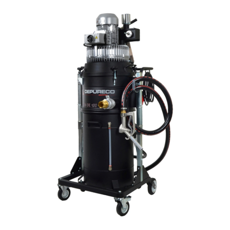
DEPURECO CLEAN OIL Series User manual
DEPURECO
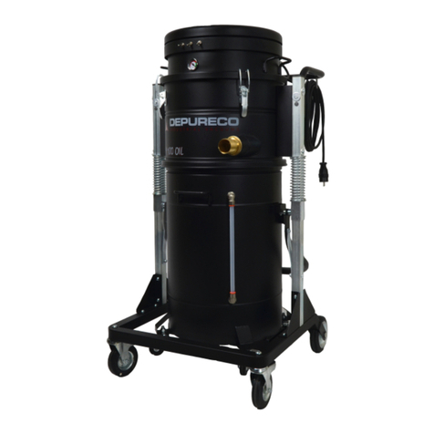
DEPURECO M 100 OIL Series User manual
DEPURECO
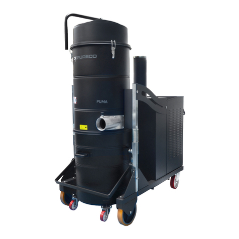
DEPURECO PUMA Series Instructions for use

DEPURECO
DEPURECO TX Series User manual
DEPURECO
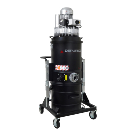
DEPURECO ECOBULL Instructions for use
DEPURECO
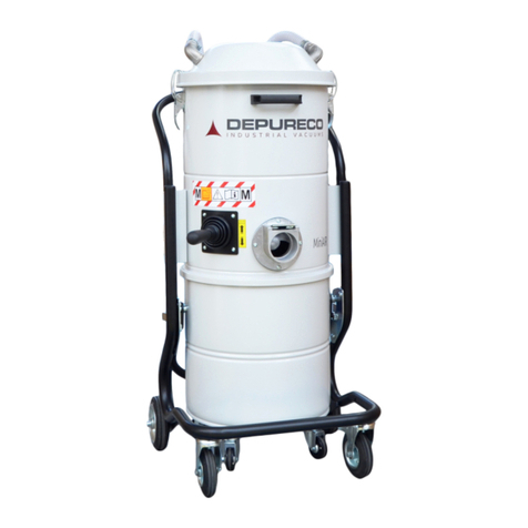
DEPURECO miniAIR Series User manual

DEPURECO
DEPURECO RAM OIL T500 Series User manual
DEPURECO
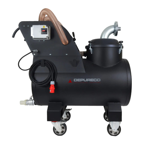
DEPURECO RAM Series Instructions for use
DEPURECO
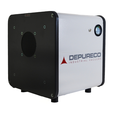
DEPURECO CLEAN AIR User manual


