VITRO
1
4
Maico Italia S.p.A.
Via Maestri del Lavoro, 12 - 25017 Lonato del Garda (BS) ITALIA
Tel. +39 030 9913575 Fax +39 030 9913766
Instruction Manual
COD. 01099-01 10/17
The equipment must be installed only by a specialised technician!
Read and apply that referred to the following pages before carrying out the installation.
Keep this manual in a safe place.
Dear Customer,
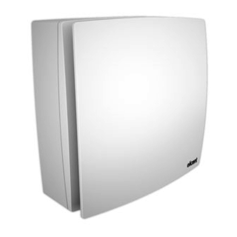
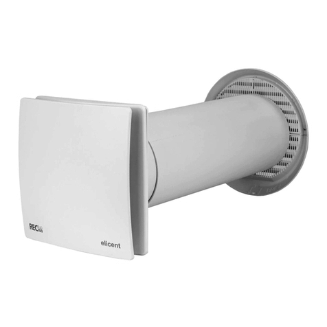
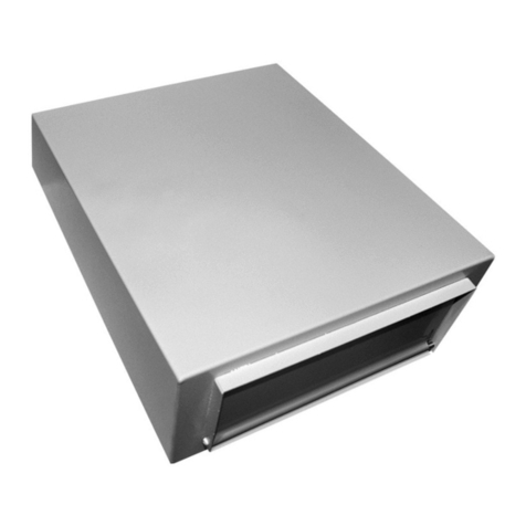
the product you have purchased is an helical fan for window or wall installation. To ensure optimum operation and guarantee
a long life, read this manual carefully that explains how to effectuate a correct installation and to use and maintain the product
properly. Following all the instructions ensures reliability and long life, both mechanically and electrically.
The manufacturer declines any responsibility for damages caused to persons or things deriving from the lack of ob-
servance of the following described instructions.
The product is constructed using state of the art technology and respects the standards in force regarding electrical equipment.
It conforms with the EMC 2014/30/EU European Directive regarding radio interference suppression and electro-magnetic
compatibility.
Installation and usage instructions
WARNING: Serious injury or death can be caused if these instructions are
not applied!
•Do not use this product for uses that are different from those for which it has been
designed.
•Afterremovingtheproductfromitspackagingensurethatitiscompleteandunda-
maged;ifindoubt,immediatelycontactaqualiedelectrician.
•Donotleavepartsofthepackagingwithinreachofchildrenorincompetentpersons.
Todisposeofthepackagingandtheapplianceattheendofitsusefulliferefertothe
recycling norms in force in your country.
•Immediatelycontactaqualiedperson(authoriseddealerorthemanufacturer)ifthe
productisdroppedorknockedtocheckitscorrectfunctioning.
•Donottouchtheappliancewithwetorhumidpartsofthebody(e.g.,handsorfeet).
•This appliance can be used by children aged from 8 years and above and persons
with reduced physical, sensory or mental capabilities or lack of experience and
knowledgeiftheyhavebeengivensupervisionorinstructionconcerninguseofthe
appliance in a safe way and understand the hazards involved. Children shall not play
with the appliance. Cleaning and user maintenance shall not be made by children
without supervision.
•The means of disconnection from the supply mains must have a contact separation
in all poles and must provide full disconnection under overvoltage category III condi-
tions.
•Ifthereisacombustible�feddevice(waterheater,gasboiler,etc.ofthesealedcham�Ifthereisacombustible�feddevice(waterheater,gasboiler,etc.ofthesealedcham-
bertype)intheroomwheretheproductistobeinstalledcheckthatthere�circulation
ofairissufcienttoensureagoodcombustionforthecorrectfunctioningofthese
devices,precautionsmustbetakentoavoidtheback�owof gasesintothe room
fromtheopenueofgasorotherfuel�burningappliances.
•Toavoidtheriskofredonotusingtheproductinthepresenceofinammablesub�Toavoidtheriskofredonotusingtheproductinthepresenceofinammablesub-
stances and vapours, such as alcohol, insecticides, petrol, etc.
•Theproductcanbeconnectedtothesupplymainsonlyifthevoltageandthefre�The product can be connected to the supply mains only if the voltage and the fre-
quency of the supply mains correspond to those written in the rating label.
•In the case of malfunction, anomaly or any type of fault disconnect the appliance
from the electrical main supply and contact a qualied person. Use only original
spare parts for repairs.
•Theelectricalsystemtowhichtheapplianceisconnectedmustconformwiththelo-
cal norms in force regarding electrical systems.
•Theappliancemustnotbeusedtoactivatewaterheaters,roomheaters,etc.
•Itisforbiddenfortheappliancetodischargeairintohotairductsusedfortheevacu-
ation of fumes coming from the combustion of stoves or other combustion devices. It
EN
LEGEND FIG. 5
Fig. 5a = Connection with speed controller for models 9/230 and 12/300
Fig.5b=Connectionformodels9/230and12/300automaticforextractiononly(makeabridgebetween5and6)
Fig.5c=Connectionformodels9/230and12/300automaticforintakeonly(makeabridgebetween5and7)
Fig.5d=Connectionformodels9/230and12/300automaticwithreversibilityswitch(makeabridgebetween5andsupply)
Fig. 5e = Connection for models 9/230 manual for extraction only
Fig.5f=Connectionformodels9/230manualforintakeonly
Fig. 5g = Connection for models 9/230 manual with reversibility switch
Fig.5h=Connectionformodels6/150manual
Fig.5m=Connectionformodels6/150automatic(makeabridgebetween5and6)
Fig.5n=Dismantlingoftheterminalblockforthemodels9/230and12/300
In case of incorrect or doubtful translation, only the Italian text applies (Translation of the original instructions).
DISMANTLING AND RECYCLING
The product has been designed and constructed using high-quality materials and components that can be recycled or re-
utilised.
Ifacrossed�outwheeledbinisillustratedonaproduct,thismeansthattheproductsatisestherequirementsofthe2012/19/
EU European Directive.
Makeinquiriesaboutthedisposalcollectionmethodsofelectricalandelectronicproductsinforceinthezoneinwhichtheproduct
must be disposed of.
Conform to the local norms regarding the disposal of waste materials and do not dispose of old products in normal domestic waste
material.Acorrectdismantlinganddisposalofproductshelpstopreventenvironmentalpollutionandpossibleinjurytohealth.
Abusivedisposaloftheproductbytheuserimpliestheapplicationofadministrativenesforeseenbythenormsinforce.
5a
5b 5c 5d
5e 5f 5g
5h 5m


