Elid EL374 User manual

EL374 Access Control Panel
Technical Manual
(Revision 1.0.1)
ELID SDN BHD

EL374 Access Control Panel
Table of Content
CHAPTE 1 .............................................................................................................................. 1
1 EL374 Access Controller .............................................................................................. 1
1.1 Introduction .......................................................................................................... 1
1.2 Configuration........................................................................................................ 2
1.3 Principle of Operation .......................................................................................... 4
1.4 ID Cards............................................................................................................... 4
1. Normal Operation.................................................................................................
1.6 Timer and Time Zone........................................................................................... 6
1.7 Logging of Activities ............................................................................................. 7
CHAPTE 2 .............................................................................................................................. 9
2. INSTALLATION............................................................................................................. 9
2.1 Introduction .......................................................................................................... 9
2.2 Physical Installation ............................................................................................. 9
2.3 Input /Output Points Installation ......................................................................... 10
2.4 Powering Up Procedures................................................................................... 10
CHAPTE 3 ............................................................................................................................ 13
3. PROGRAMMING MODE............................................................................................ 13
3.1 The Operation of Keypad................................................................................... 13
3.2 Commands......................................................................................................... 14
CHAPTE 4 ............................................................................................................................ 16
4. TIME MENU................................................................................................................ 1
4.1 Set Date / Time .................................................................................................. 16
4.2 Set Timer............................................................................................................ 17
4.3 Set Holiday......................................................................................................... 19
4.4 Set Access Time Zone ....................................................................................... 19
4. Set Miscellaneous Time Zone............................................................................ 21
CHAPTE 5 ............................................................................................................................ 23
5. CARD MENU .............................................................................................................. 23
.1 Add Card Via Reader......................................................................................... 23

.2 Add Card Via Keypad ........................................................................................ 24
.3 Remove Card Via Reader.................................................................................. 2
.4 Remove Card Via Keypad ................................................................................. 26
. Set Code Entry................................................................................................... 26
CHAPTE 6 ............................................................................................................................ 28
. Set-up MENU.............................................................................................................. 28
6.1 Set Unit Number & Baud Rate........................................................................... 28
6.2 Set Door Parameter ........................................................................................... 29
6.3 Set Door Contact Type & Lock Release Time ................................................... 30
6.4 Set Auxiliary Output ........................................................................................... 30
6. Set EL Z ID Code and Customer Code ............................................................ 31
6.6 Power Save ...................................................................................................... 33
6.7 Print Transaction Report and Card Database.................................................... 33
6.8 Backup & Restore .............................................................................................. 34
6.9 Language ........................................................................................................... 34
CHAPTE 7 ............................................................................................................................ 36
.9 SELF-TEST COMMAND ........................................................................................ 3
7.1 Input Test............................................................................................................ 36
7.2 Output Test......................................................................................................... 37
7.3 Serial Port Test................................................................................................... 37
7.4 Keypad Test ....................................................................................................... 38
7. Reader Test........................................................................................................ 38
7.6 Memory Test....................................................................................................... 38
7.7 Hard Reset......................................................................................................... 39
7.8 Test CPU Frequency............................................ Error! Bookmark not defined.
EL374 Access Control Panel Technical Manual
1
CHAPTE 1
1 EL374 Access Controller
1.1 Introduction
EL374 is Microprocessor controlled equipment that combines access controller, card reader
and keypad in single unit. It is equipped with a 122 X 32 pixels backlit graphical LCD and a
12-key touch sense keypad.
EL374 has the following features:
Stand-alone operation or networking operation with PC.
24 timers, each with 2 sets of start-stops.
10 sets of 8-day time zones (Monday to Sunday plus holiday)
Stored up to 4000 ID cards (2000 ID with programmable PIN, or 4000 ID with pre-set
PIN)
Logs 2000 transactions
Automatic PIN activation by time zone
Automatic lock release by time zone
Operation mode: Card only, Card + PIN, PIN.
Optional EL Z remote relay unit to improve security, with additional 1 sensor input and 1
auxiliary output.
LAN option using EA792T
In-circuit firmware update by serial communication.

EL374 Access Control Panel Technical Manual
2
1.2 Configuration
The drawings below show the basic set-up of an EL374 system. There are 4 configurations
available.
Stand alone, normal mode
Stand alone, secure mode
PC linked, through RS48 of Local Area Network (LAN)
In the standalone mode, all programming is carried out using built-in keypad.
In the PC linked mode, all operations can be controlled from PC running access management
software such as E.WIN or WINPRO or SPHERE.

EL374 Access Control Panel Technical Manual
3
The first configuration has low security, because the EM lock is connected directly to EL374
and can be tampered with, as EL374 is installed in a non-secure area.
For better security, EL374 should be fitted with an EL Z remote relay unit mounted in a secure
zone as shown in the second diagram.
Note that in this mode, all external devices are connected to EL Z. Furthermore, EL Z
provides an extra input point and extra output point.
There are 3 external devices connected to EL374 (or EL Z, if it is used).
Device Description
Door Sensor Device that can detect whether the door open or shut.
Electric Lock Electrically operated device that can lock or unlock a door depending
on whether electricity is supplied to the device or not.
Exit Push Button Push button switch, which when activated, will unlock the door by
energizing the electric lock.
You need to supply a 12VDC power source with at least 0.7A capacity, excluding the power
consumption of the electric locking device. In most installations, a charger with sealed
lead-acid battery on float charge should be provided, so that the door can continue to work
even when there is power outage. The charger should maintain float charge voltage 13.8V.
There should also be a low-voltage cut off, so that the battery is disconnected from EL374
when voltage falls below 10V. This low voltage cut-off is particularly important if you are using
EM locks. When voltage falls below 10V, EL374 will shut down, and will not read a card
presented, nor will it respond to any command from PC. At the same time, the EM lock will still
be energized, because there is 10V of supply across it. Therefore, the door will be held locked

EL374 Access Control Panel Technical Manual
4
until battery drains out, or power supply returns.
Elid sells a range of chargers specially made for Access applications.
If EL Z is used, it provides 1 sensor input and 1 auxiliary output. This sensor input may
function as an alarm input or a status input, depending how the auxiliary output is configured.
The auxiliary output point can be programmed as a sensor alarm output, or door open alarm,
or general purpose output, or valid exit output
When configures as sensor alarm output, it will treat sensor input as a alarm point, which can
be armed or disarmed
When configured as a door open alarm output, it will be activated when the door protected by
EL374 is forced open or left open.
When programmed as a General Purpose (GP) output, it can be switched on manually or
automatically by time zone.
When program as Valid Exit output, it will be activated when there is valid exit transaction.
1.3 Principle of Operation
The EL374 system uses cards to unlock a door. Each person eligible to enter the door is
issued with an ID card. The type of ID card used will depend on the type of readers that EL374
is equipped with. Elid offers different models of EL374 fitted with different types of readers.
When a person presents his card to the reader, the card number is read and compared with
the list of ‘valid’ numbers held inside the memory of EL374. If the number is found, EL374 will
check to see whether this particular card user is allowed entry at the particular day. If the
answer is ‘yes’, and the EL374 is configured as card only mode, it will activate the electric lock
to unlock the door. If the EL374 is configured as card + pin mode, then it will wait for the PIN
(Personal Identification Number) to be keyed in. If any of the above 3 tests fail, the door will not
be unlocked.
1.4 ID Cards
As stated in the previous section, encoded ID cards are used as ‘keys’ for opening doors.
Cards can be EM proximity, HID Proximity, Mifare smart cards, depending on the model of
reader you have purchased. However, card format used must conform to the following:
ELID Wiegand Format
These are cards encoded with propriety Elid format.
Standard Wiegand 26-Bit Format
A card with the standard 26-bit Wiegand format will have a customer code in the range 0-127,
and ID number from 0-6 3 . Any card can be assigned as a Master Card. All cards with ID

EL374 Access Control Panel Technical Manual
5
number larger than 60,000 are automatically treated as Special Cards, and should not be
used.
Free Wiegand Format
The card can be encoded with up to 48 bits, and you can specify any bits, up to maximum of 20
bits as containing the ID number to be read.
For example, you can specify that EL374 reads 40 bits of the card output, and select bits 20 to
40 as the ID number. In this case, the first 20 bits will be ignored, and only bits 20 to 40 are
read.
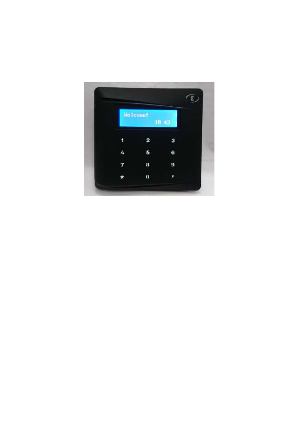
1.5 Normal Operation
When the EL374 is operating normally, you will see ‘Welcome!’ and the time (HH:MM)
displayed at the LCD display. The first 2 digits indicate the hours and the next 2 digits the
minutes. Time is indicated in 24-hour format. For example, 4 pm is indicated as 16:00. The
‘Welcome!’ which located at the upper row of LCD will blink once every second. This condition
indicates that the equipment is ready to read a card.
Depending on how the EL374 is programmed, entry is granted on the following conditions:-
Is the card properly read?
Is the card number in the list of valid cards stored in EL374 memory?
Is the Access Time Zone correct? In other words, is the card allowed access at this
particular day of the week and this particular time?
Is the EL374 set to ‘No-Entry’ mode, in this mode, none of the card can access.
Is the EL374 set to Card + PIN mode? If so, it will check the 4-digit PIN entered
The LCD screen of the EL374 unit will respond to the different situations above with different
displays as detailed below:-
Error ead : The card ID code cannot be read, which may be due to card
damage or use of cards with incompatible format.
Wrong CustCode : Card’s customer code does not match the Controller’s customer
code.
Not enrolled : The number is not found in the memory.
Wrong TimeZone : The number is found in the memory, but the category or time zone
of the card is such that it cannot enter the door at this particular time.
No Entry EL374 is set to “No Entry” mode.
If the card number is found in the memory, and the access time zone is correct. In other words,
the card is allowed entry at this particular time. Then one of the following will take place:-
If the EL374 is programmed to “Card-only” mode, then the display will show “GO” and
the door is unlocked.
If the EL374 is programmed to “Card+PIN” mode, then the display will show “Enter

EL374 Access Control Panel Technical Manual
6
PIN?” requesting the user to key in the 4-digit PIN code. As each number is keyed in,
there will be a “beep” sound and a”*” is displayed. If the code is correctly entered, the
display will show “GO” and the door is unlocked. If the code is wrong, the display will
show “Wrong PIN”, and the door will not open.
When a person wishes to exit, he should push the Exit Push Button. This will activate the
Electric Lock to unlock the door. However, an exit reader can be installed in lieu of push button,
in which case he should present his card at the exit reader. The advantage of putting an exit
reader is that you can tell who has exited the room.
Note that each time the Electric Lock is activated, it does so for a limited time period, (factory
setting is seconds, but can be changed to other duration) after which the door is locked back.
The user should open the door during this period; otherwise the door will be locked again.
1.6 Timer and Time Zone
A powerful feature provided by EL374 is the ability to grant or deny access depending on time.
This is done by setting “Timers” and “Access Time Zone”. A timer has 2 sets of “start” and “end”
times. There are 24 timers in EL374. For example, you may set up the timers as follows:-
Timer # Start Time 1 End Time 1 Start Time 2 End Time 2
1 (Predefined) 00:00 00:00 00:00 00:00
2 (Predefined) 00:00 23: 9 00:00 00:0
3 08:30 12:30 13:30 17:30
4 07:00 19:00 00:00 00:00
07:00 13:00 00:00 00:00
6 07:00 08:00 18:00 19:00
… … … … …
Timer # Start Time 1 End Time 1 Start Time 2 End Time 2
… … … … …
24 13:00 18:00 00:00 00:00
In the above example, Timer 3 is set to be activated between 08:30 and 12:30 for the first
period, and 13:30 to 17:10 for the second period. If this timer is assigned to, say, lock output,
then the door will be open during the 2 periods 08:30-12:30 and 13:30-17:30. The door will be
locked at other times.
In real life, we often need different timers for different day of the week, and if a particular date
happens to be a holiday, we will need a different timer. This is handled by the ‘Access Time
Zone’ command. The Time Zone command allows you to divide your staff into different groups
or categories, each with its own unique set of times to control when entry is granted.
An example of such a requirement for time zone is shown in the table below. Note that the

EL374 Access Control Panel Technical Manual
7
timers used are those referred ealier.
In this example, staffs are divided into 4 groups:-
Time Zone 2 is for company chief executives, who may come in at any time, any day.
This is a predefined time zone, and no programming is needed.
Time Zone 3 is for managers who can come in from 7 am to 7 pm from Monday to Friday,
but can only come in from 7 am to 1 pm on Saturday, and cannot come in on Sunday and
holiday. This is achieved by giving timer 4 for Monday, Tuesday, Wednesday, Thursday
and Friday, and timer for Saturday, and timer 1 for Sunday and holiday.
Time Zone 4 is for general office staff who can come in only from 8:30 am to 12:30 pm
and from 1:30 pm to :30 pm from Monday through Friday. This is achieved by giving
timer 3 for Monday, Tuesday, Wednesday, Thursday, Friday, and timer 1 for Saturday,
Sunday and holiday.
Time Zone is for cleaners who can come in only from 7 am to 8 am and 6 pm to 7 pm
on Tuesday.
Timer For
Category
SUN MON TUE WED THU F I SAT HOL
1 Predefined as ‘No Entry’ at all times
2 Predefined as entry permitted at all times
3 1 4 4 4 4 1
4 1 3 3 3 3 3 1 1
1 1 6 1 1 1 1 1
It is up to you to program the start and end times for each timer. It is also up to you to allocate
any of the 24 timers for any day of the week and for each of the 8 programmable time zones
(time zones 1 & 2 are pre-defined).
1.7 Logging of Activities
The EL374 is able to log up to 2000 records of the latest activities (or transactions) occurring at
the door it is controlling. Each record is stored with date, time, card ID and transaction code.
The following is a typical sequence of records, where the first 4 numbers are the date in
day/month, the next 4 numbers are the time in hour/minute, the next 6 digits are the card ID
and the last digit is the transaction code.
28/02 14:40 012700 0
28/02 14:50 051788 3
28/02 14:55 012702 0
Table of contents
Other Elid Control Panel manuals


