Elid EL1335 User manual

EL1335
ACCESS CONTROL PANEL
USER GUIDE
(Revision 1.1.11)
ELID SDN BHD

EL1335 Access Control Panel
User Guide
Revision 1.1.11
1
EL1335 ACCESS CONTROL PANEL
USER GUIDE
1.
SYSTEM INITIALIZATION……………………………………………………….
4
1.1 TO COLD START……………………………………………………………
4
1.2 TO PROGRAM THE MASTER CARD…………………………………….
5
1.3 SETTING CARD FORMAT …………………………………………………
5
1.4 TO USE USER CARDS’ PRESET OR USER-DEFINED PIN…………..
6
1.5 BEFORE OPERATION……………………………………………………..
7
2.
MAIN COMMANDS……………………………………………………………….
8
3.
SPECIAL CARD………………………………………………………………….
27
3.1 INTRODUCTION……………………………………………………………
27
3.2 REGISTERING SPECIAL CARDS………………………………………..
28
3.3 APPLY A SPECIAL CARD……………………………………………….
29

EL1335 Access Control Panel
User Guide
Revision 1.1.11
2
4.
PROGRAMMABLE PIN…………………………………………….……………
35
5.
SELF-TEST COMMANDS.………………………………………………………
38
6.
FIRMWARE UPDATE…………………………………………………………....
44
7.
DATA STORAGE CAPACITY………………………………………………..…
45
EL1335 Access Control Panel
User Guide
Revision 1.1.11
3
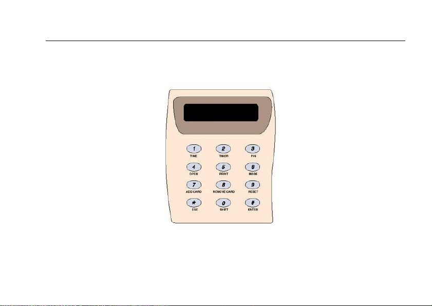
EL1335 ACCESS CONTROL PANEL
Keypad Layout

EL1335 Access Control Panel
User Guide
Revision 1.1.11
4
CHAPTER 1
1. SYSTEM INITIALIZATION
1.1 TO COLD START
Hold down keys "1" and "3" on the keypad and simultaneously switch off and then switch back
on the power supply. (Alternatively, hold down keys "1" and "3" on the keypad and press the reset
switch while power is on.)
Release the two keys 3 seconds after the power supply is switched back on. If the cold start has
been properly performed, the display will show "PIN". When the display shows "PIN", key in the
6-digit Cold Start PIN code (packed in an envelope in your EL1335 package, otherwise
‘123456’).
EL1335 Access Control Panel
User Guide
Revision 1.1.11
5
1.2 TO PROGRAM THE MASTER CARD
If the PIN code has been correctly entered, the display will change to "MAST". Now, key-in the 6-
digit card number of your Master Card.
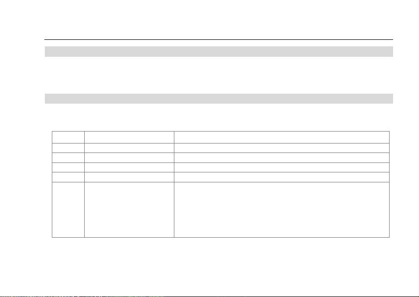
1.3 SETTING CARD FORMAT
The display will now show "CT". Key in the card type according to following code:
Code
Meaning
Details
0
Reserved
1
Reserved
2
Wiegand 26 format
-
3
Wiegand HID format
-
4
Wiegand Free Format
For this format, you need to set offset, number of bits &
Max bits:
Co.<00> Set offset bit
ML.<00> Set No. of bit as card No./Card Size
CL.<00> Max No. of bit to take/length of card number for
reading
EL1335 Access Control Panel
User Guide
Revision 1.1.11
6
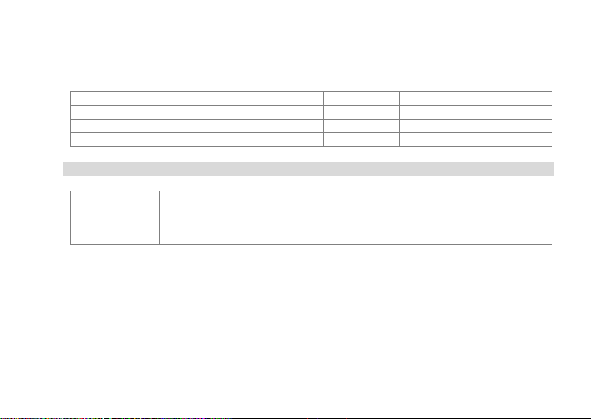
Limits of bit settings for Card Type 4 (Free Wiegand)
Limits
Symbol
No. of Bits
Max no. of bits to make up a card number
ML
40 (000000~999999)
Max bits to be taken for reading a card number
CL
20
Max offset bits to read a card number
Co
20
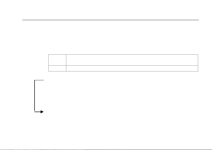
1.4 TO USE USER CARDS’ PRESET OR USER-DEFINED PIN
Display
What to do
PT.<N>
Key in the code according to your application
0 = To use preset PIN
1 = To use user-programmable PIN
The display will then immediately change to "db 1".
After a few seconds, the display will then show the current system time, in hours and minutes.
The controller has now been initialized.

EL1335 Access Control Panel
User Guide
Revision 1.1.11
7
1.5 BEFORE OPERATION
A "burn-in" operation should be performed on the new PCB for EL1335 (Revision 1.0) to ensure
the functionality of the backup battery.

EL1335 Access Control Panel
User Guide
Revision 1.1.11
8
CHAPTER 2
2. MAIN COMMANDS
Note: To access the programming menu, badge your Master Card at the EL1335 card reader.
Key Command
1 DATE/TIME/Daylight Saving Time
2 Timer
3 Category
4 Door Parameters (PLR/PIN MODE/NO ENTRY MODE)
5 Time Zones (ALR TZ/PIN DISABLE TZ/GP-TZ)
6 Holidays
7 ADD Cards by reader
8 Remove Cards by reader
9 Clear Memory

EL1335 Access Control Panel
User Guide
Revision 1.1.11
9
Shift + Key Command
0 SELF-TEST
1 PRINT
2 Unit Number/Baud Rate
3 Door/Contact Type/Lock Release Time/Keypad buzzer alarm
4 Select Output type / Sensor type / Set Anti pass back
5 Customer Code
6 Pin Only mode ( 20 sets )
7 ADD Cards by Keys
8 Remove Cards by keys
9 Setting Special Card Range
Note:
Shift Key Commands require you to press 0 (shift) first, follows by the command key. Eg.
Press 0 followed by 0 again to activate a self-test command, which is another digit (See Section
5).

EL1335 Access Control Panel
User Guide
Revision 1.1.11
10
Key 1
Setting Date/Time/Daylight Saving Time
t1.<YY> year
t4.<HH> hour
t2.<MM> month
t5.<MM> minute
t3.<DD> day
t6.<SS> second
t7.<W> 0=Sunday, 1=Monday .....6=Saturday
DSt Daylight Saving Time
S1. <MM> DST start Month field
S2. <DD> DSTstart Day field
S3. <HH> DSTstart Hour field
S4. <MM> DST start Minute field
E5. <MM> DST end Month field
E6. <DD> DST end Day field
E7. <HH> DST end Hour field
E8. <MM> DST end Minute field
Key 2
Setting Timer
EL1335 caters for 22 sets of programmable timers. Each set consists of 4 entries:
start hour, start minute, end hour and end minute. So, with 22 sets of timers (2
sets for each timer between tr.03 and tr.24), there are total of 176 entries, for
both hour and minute. Each entry is designated with S<x> or E<y>, where x and y
run between 1 and 4.

EL1335 Access Control Panel
User Guide
Revision 1.1.11
11
Notethat timers #01 and #02 are pre-defined as below:
Timer 01
(tr.01)
No Entry Timer (for Stand-alone only, and this may be changed
using software, such as E.WIN)
Timer 02 02
(tr.02)
Free Entry Timer
Programming example:
(tr.<03>)
1st set
S1.<HH> Start hour
S2.<MM> Start minute
2nd set
S3.<00> Start hour
S4.<00>Start minute
E1.<HH> End hour
E2.<MM> End minute
E3.<00> End hour
E4.<00>End minute

EL1335 Access Control Panel
User Guide
Revision 1.1.11
12
(tr.<04>)
1st set
S1.<00> Start hour
S2.<00>Start minute
2nd set
S3.<00> Start hour
S4.<00>Start minute
E1.<00> End hour
E2.<00>End minute
E3.<00> End hour
E4.<00>End minute
EL1335 Access Control Panel
User Guide
Revision 1.1.11
13
Key 3
Setting Access Time Zone Category
CA.<N>
N is the Time Zone category number between 01
and 09
The following time zones are the predefined once:
CA.01
No Entry Time Zone (Fixed in stand-alone mode
only;
This setting may be changed by software such as E.WIN.)
CA.02
Free EntryTime Zone
CA.03 to CA.09
are programmable (7 of them). Each Time Zone
category
constitutes the following days' timer settings (01 and 24).
<day>.<timer>
Meaning
Su.<00>
Timer for Sundays
Mo.<00>
Timer for Mondays
Tu.<00>
Timer for Tuesdays
We.<00>
Timer for Wednesdays
Th.<00>
Timer for Thursdays
Fri.<00>
Timer for Fridays

EL1335 Access Control Panel
User Guide
Revision 1.1.11
14
Sa.<00>
Timer for Saturdays
Ho.<00>
Timer for all pre-set Holidays
<00> is to be set with timer between 01 and 24
Key 4
Setting Door Command
oD.<00>
1= Door permanently unlocked; 0 = normal
Pn.<00>
1= Card+PIN mode on; 0= Card+PIN mode off
NE.<00>
1= No entry, door open disabled; 0 = normal
<00> is to be set either 0 or 1.
EL1335 Access Control Panel
User Guide
Revision 1.1.11
15
Key 5
Miscellaneous Time Zones
Each of the Code Displays below will be automatically displayed for 1 second.
This is followed by the timer entries for weekdays and holidays.
Code Display
Meaning
ALR
Automatic Lock release time zone
P-TZ
Automatic PIN time zone
GPT0
General Purpose time zone for output 1
GPT1
General Purpose time zone for output 2
To enable general purpose time zones for outputs, you
must set the output point (Command Shift-Key 4) to GP output.
Output 1: "o1 S" to 1.
Output 2: “o2 S” to 0.
<day>.<timer>
Meaning
Su.<00>
Timer for Sundays
Mo.<00>
Timer for Mondays

EL1335 Access Control Panel
User Guide
Revision 1.1.11
16
Tu.<00>
Timer for Tuesdays
We.<00>
Timer for Wednesdays
Th.<00>
Timer for Thursdays
Fri.<00>
Timer for Fridays
Sa.<00>
Timer for Saturdays
Ho.<00>
Timer for all pre-set Holidays
Where, <00> is to beset with timer between 01 and 24
Note:
If the clock time falls within the periods of the set Time Zones, he programmed
actions will immediately take effect. Time Zones are checked every minute by the
EL1335 system.

EL1335 Access Control Panel
User Guide
Revision 1.1.11
17
Key 6
Setting Holidays
There are 20 holiday records. Each holiday consists of "month and day " as shown
below:
01.<MM>
1st holiday, month
02.<DD>
1st holiday, day value
03.<MM>
2nd holiday, month
04.<DD>
2nd holiday, day value
05.<MM>
3rd holiday, month
06.<DD>
3rd holiday, day value
Press '#' to move further down the record sequence.
Press key '*' to save and exit in themiddle of the sequence.
Example:
To set the 1st of January (New Year's Day) as a holiday, first press Key 6 to enter
"Set Holidays" mode. The display will show "01" for holiday month set#1.
Enter 01 followed by Key "#" for January. The display show "02" for holiday
day set#1. Enter 01 followed by Key # for 1
st
. The display will show "03" for
holiday month set#2. Enter "*" to save and exit.

EL1335 Access Control Panel
User Guide
Revision 1.1.11
18
Key 7
Add Card Via Reader
CA.<N>
To set door access category between 1 and 9.
INST
Waiting for cards to be presented to reader for
recording/registering, cards can be presented one after
another.
Key 8
Remove/Delete Card Via Reader
DELC
Waiting for cards to be presented to reader for deletion
cards can be presented one after another.
Key 9
Clear Memory
rESt
Press '#' at this prompt to permanently erase the contents
of the EL1335's memory database. Press '*' to escape from
the memory clearing command.

EL1335 Access Control Panel
User Guide
Revision 1.1.11
19
Shift + Key 1
Print Data To The PC Screen
Setup:
Before printing from a standalone EL1335 unit:
Connect the EL1335 unit to a PC via RS232 serial cable.
Run a Hyperterminal program. In the Hyperterminal, select the
Serial
Communication port connected to the EL1335 and set the Baud rate used by
the EL1335 unit (default is 2400 but this can be changed.
See next section, ‘Shift + Key 2’).
Command:
Pr.<0>
0 = print transaction log
1 = print card database
Table of contents
Other Elid Control Panel manuals

Popular Control Panel manuals by other brands


PS Engineering
PS Engineering PMA8000BT System installation and operation manual

BFT
BFT RIGEL 6 installation manual

Genius
Genius JA592 Use and Installation Instructions

Pentair
Pentair Hydromatic H-03-000 Installation and service manual

Fabman
Fabman Bridge FB-V2 user manual

Climma
Climma 210705 Service manual