BFT HYDRA-R User manual

D811425 ver. 05 17-10-2006
8888
I
GB
F
D
E
P
QUADRO COMANDO
CONTROL PANEL
CENTRALE DE COMMANDE
STEUERPLATINE
CUADRO DE MANDOS
QUADRO DE COMANDO
Via Lago di Vico, 44
36015 Schio (VI)
Tel.naz. 0445 696511
Tel.int. +39 0445 696533
Fax 0445 696522
Internet: www.bft.it
E-mail: [email protected]
HYDRA-R
8027908 2 3 5 0 3 9
ISTRUZIONI D’USO E DI INSTALLAZIONE
INSTALLATION AND USER’S MANUAL
INSTRUCTIONS D’UTILISATION ET D’INSTALLATION
INSTALLATIONS-UND GEBRAUCHSANLEITUNG
INSTRUCCIONES DE USOY DE INSTALACION
INSTRUÇÕES DE USO E DE INSTALAÇÃO

2- HYDRA-R - Ver. 05
D811425_05

HYDRA-R - Ver. 05 - 3
D811425_05
MANUALE D’USO
ITALIANO
Nel ringraziarVi per la preferenza accordata a questo prodotto, la ditta è certa che da
esso otterrete le prestazioni necessarie al Vostro uso.
Leggete attentamente l’opuscolo ”Libretto istruzioni” che lo accompagna in quanto
esso fornisce importanti indicazioni riguardanti la sicurezza, l’installazione, l’uso e la
manutenzione. Questo prodotto risponde alle norme riconosciute della tecnica e delle
disposizioni relative alla sicurezza. Confermiamo che esso è conforme alle seguenti
direttive europee: 89/336/CEE, 73/23/CEE, 98/37/CEE e loro modifiche successive.
1) GENERALITÁ
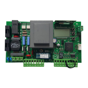
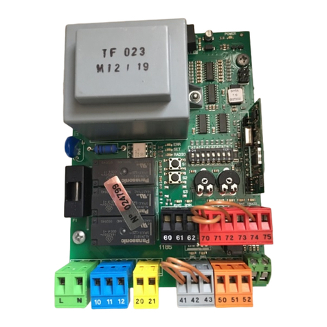
Il quadro comandi HYDRA-R è adatto a comandare 1 o 2 attutatori della serie PHEBE,
progettati per automatizzare basculanti di vario tipo. Il quadro può essere:
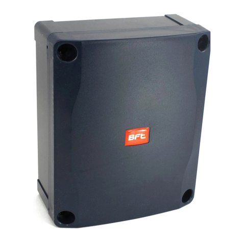
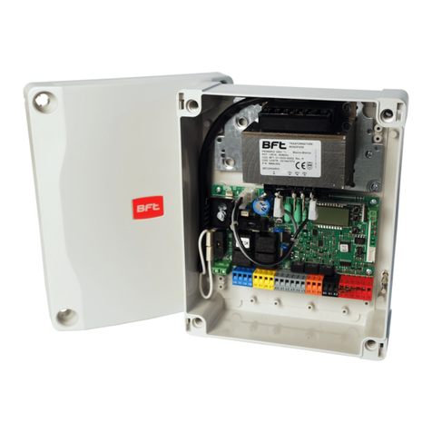
- Presente a bordo della serie PHEBE (fig.1)
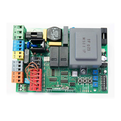
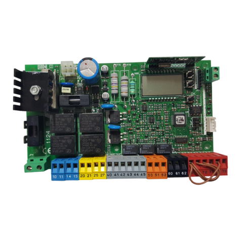
- Montata su quadro a parete (fig.2) da utilizzare con attuatori senza centralina a
bordo (serie PHEBE -SQ).
Nel caso si voglia automatizzare una basculante con due motori, sono possibili 2
configurazioni:
- n°1 PHEBE + n°1 PHEBE -SQ
- n°2 PHEBE -SQ + n°1 HYDRA-R con quadro,montata a parete.
Viene fornito dal costruttore con impostazioni funzionali standard.Qualsiasi variazione,
deve essere impostata mediante il programmatore a display incorporato o mediante
UNIPRO. La Centralina supporta completamente il protocollo EELINK.
2) FUNZIONI
PER L’INSTALLATORE: compilare la tabella con in parametri impostati al fine di
facilitare future modifiche e manutenzioni.
Tra parentesi quadre [ ] sono indicati i valori di fabbrica.Per le logiche di funzionamento,
[ OFF ] indica opzione non attiva, [ ON ] indica opzione attiva.
MENU PARAMETRI
Tempo Chiusura Automatica [10s] ___
Coppia motori apertura [80%] ___
Coppia motori chiusura [80%] ___
Coppia motori apertura in rallentamento [50%] ___
Coppia motori chiusura in rallentamento [50%] ___
Tempo veloce in apertura [15s] ___
Tempo veloce in chiusura [15s] ___
Velocità rallentamento [0] ___
T.START [075] ___
Indirizzo di zona per comandi centralizzati [0] ___
MENU LOGICHE
Richiusura automatica attiva (TCA) [ OFF ] ___
Logica di funzionamento a 3 Passi [ OFF ] ___
Blocca Impulsi [ OFF ] ___
Fotocellule in apertura [ OFF ] ___
Test fotocellule [ OFF ] ___
Spia cancello aperto o II° canale radio [ OFF ] ___
Mantenimento blocco [ OFF ] ___
Preallarme [ OFF ] ___
Radioricevitore a codice fisso [ OFF ] ___
Programmazione radiocomandi [ OFF ] ___
Scheda in anello chiuso per comandi centralizzati [ OFF ] ___
Scheda master per comandi centralizzati [ OFF ] ___
Logica 1 [ OFF ] ___
Logica 2 [ OFF ] ___
3) DEMOLIZIONE
Attenzione: Avvalersi esclusivamente di personale qualificato.
L’eliminazione dei materiali va fatta rispettando le norme vigenti. Nel caso di demolizio-
ne, non esistono particolari pericoli o rischi derivanti dal prodotto stesso. È opportuno,
in caso di recupero dei materiali, che vengano separati per tipologia (parti elettriche
- rame - alluminio - plastica - ecc.).
4) SMANTELLAMENTO
Attenzione: Avvalersi esclusivamente di personale qualificato.
Nel caso la centralina venga smontata per essere poi rimontata in altro sito bisogna:
• Togliere l’alimentazione e scollegare tutto l’impianto elettrico.
• Nel caso alcuni componenti non possano essere rimossi o risultino danneggiati,
provvedere alla loro sostituzione.
5) AVVERTENZE
• Assicurarsi che sia presente sulla rete di alimentazione dell’automazione, un
interruttore o un magnetotermico onnipolare con distanza di apertura dei contatti
uguale o superiore a 3,5 mm.
• Assicurarsi che sia presente a monte della rete di alimentazione un interruttore
differenziale con soglia da 0.03A.
• Assicurarsicheidispositividisicurezzaapplicatialcancellosianosemprefunzionanti,
altrimenti togliere alimentazione, sbloccare i motori e rivolgersi subito a personale
qualificato.
• Non permettere a persone e bambini di sostare nell’area d’azione dell’automazione.
• Non lasciare radiocomandi o altri dispositivi di comando alla portata dei bambini
onde evitare azionamenti involontari dell’automazione.
• L’utilizzatore deve evitare qualsiasi tentativo di intervento o riparazione
dell’automazione e rivolgersi solo a personale qualificato.
Il buon funzionamento dell’attutatore è garantito solo se vengono rispettate i dati
riportatiinquestomanuale.Ladittanonrispondedeidannicausatidall’inosservan-
za delle norme di installazione e delle indicazioni riportate in questo manuale.
Le descrizioni e le illustrazioni del presente manuale non sono impegnative.
Lasciando inalterate le caratteristiche essenziali del prodotto, la Ditta si riserva
di apportare in qualunque momento le modifiche che essa ritiene convenienti
per migliorare tecnicamente, costruttivamente e commercialmente il prodotto,
senza impegnarsi ad aggiornare la presente pubblicazione.
USER’S MANUAL ENGLISH
Thank you for buying this product, our company is sure that you will be more than
satisfied with the product’s performance. The product is supplied with a “Warnings”
leaflet and an “Instruction booklet”. These should both be read carefully as they
provide important information about safety, installation, operation and maintenance.
This product complies with the recognised technical standards and safety regulations.
We declare that this product is in conformity with the following European Directives:
89/336/EEC and 73/23/EEC, 98/37/EEC (and subsequent amendments).
1) GENERAL OUTLINE
The HYDRA-R control panel is suitable for controlling 1 or 2 PHEBE series operators,
designed to automate different types of overhead doors. The panel can be either
- fitted on board the PHEBE series (fig. 1) or
- wall-mounted (fig. 2), when to be used with operators having no control units on
board (PHEBE – SQ series).
For automation of an overhead door with two motors, 2 configurations are possible:
- no. 1 PHEBE + no. 1 PHEBE -SQ
- no. 2 PHEBE -SQ + no. 1 HYDRA-R with panel, wall mounted.
It is supplied by the manufacturer with standard functional settings.Any alteration must
be set by means of the incorporated display programmer or by means of UNIPRO.The
Control unit completely supports the EELINK protocol.
2) FUNCTIONS
FOR THE INSTALLER: fill in the table with the parameters set, in order to facilitate
future modifications and maintenance operations.
The factory-set values are specified within square brackets [ ]. For function logics, [
OFF ] indicates a non-active option and [ ON ] indicates an active option.
PARAMETER MENU
Automatic closing time [10s] ___
Opening motor torque [80%] ___
Closing motor torque [80%] ___
Slow-down opening motor torque [50%] ___
Slow-down closing motor torque [50%] ___
Fast opening time [15s] ___
Fast closing time [15s] ___
Slow-down speed [0] ___
T.START [075] ___
Zone address for centralised commands [0] ___
LOGIC MENU
Automatic closing time (TCA) [ OFF ] ___
3-Step function logic [ OFF ] ___
Impulse lock [ OFF ] ___
Photocells on opening [ OFF ] ___
Photocells Test [ OFF ] ___
Gate-open warning light or 2nd radio channel [ OFF ] ___
Lock hold [ OFF ] ___
Pre-alarm [ OFF ] ___
Fixed-code radio receiver [ OFF ] ___
Radio programming [ OFF ] ___
Closed-loop board for centralised commands [ OFF ] ___
Master board for centralised commands [ OFF ] ___
Logic 1 [ OFF ] ___
Logic 2 [ OFF ] ___
3) SCRAPPING
Warning: This operation should only be carried out by qualified personnel.
Materials must be disposed of in conformity with the current regulations. In case of
scrapping, the automation devices do not entail any particular risks or danger. In case
of materials to be recycled, these should be sorted out by type (electrical components,
copper, aluminium, plastic etc.).
4) DISMANTLING
Warning:Thisoperation shouldonlybecarriedoutbyqualifiedpersonnel.Whenthe
control unit is disassembled to be reassembled on another site,proceed as follows:
• Disconnect the power supply and the entire electrical installation.
• In the case where some of the components cannot be removed or are damaged,
they must be replaced.
5) WARNING
• Makesurethatanomnipolarormagnetothermalswitch,havingacontactopeningdistance
equal to or greater than 3,5 mm, is fitted to the automation power supply mains.
• Make sure that a differential switch with a 0.03A threshold is fitted before the power
supply mains.
• Make sure that all safety devices installed on the gate are always in working order;
otherwise,disconnect the powersupply, releasethe motors and immediately request
assistance from qualified personnel.
• Do not allow persons or children to remain within the automation operation area.
• Keep radio control or other control devices out of children’s reach, in order to avoid
unintentional automation activation.
• The user must avoid any attempt to carry out work or repair on the automation
system, and always request the assistance of qualified personnel.
Correct controller operation is only ensured when the data contained in the
present manual are observed.The company is not to be held responsible for
any damage resulting from failure to observe the installation standards
and the instructions contained in the present manual.
Thedescriptionsandillustrationscontainedinthepresentmanualarenotbinding.
The Company reserves the right to make any alterations deemed appropriate
for the technical, manufacturing and commercial improvement of the product,
while leaving the essential product features unchanged, at any time and without
undertaking to update the present publication.

4- HYDRA-R - Ver. 05
D811425_05
BEDIENUNGSANLEITUNG DEUTSCH
Wir danken Ihnen, daß Sie sich für diese Anlage entschieden haben.
Ganz sicher wird sie mit ihren Leistungen Ihren Ansprüchen vollauf gerecht werden.
Lesen Sie aufmerksam die Broschüre mit den „GEBRAUCHSANWEISUNGEN“ durch,
die dem Produkt beiliegen. Sie enthält wichtige Hinweise zur Sicherheit, Installation,
Bedienung und Wartung der Anlage.Dieses Produkt genügt den anerkannten techni-
schen Normen und Sicherheitsbestimmungen. Wir bestätigen, daß es mit folgenden
Europäischen Richtlinien übereinstimmt: 89/336/EWG, 73/23/EWG, 98/37/EWG und
nachfolgende Änderungen.
1) ÜBERSICHT
Die Steuerung HYDRA-R eignet sich zur Führung von 1 oder 2 Antrieben der Serie
PHEBE, mit denen Schwingtore verschiedenerTypen automatisiert werden.Die Steue-
rung kann folgendermaßen ausgeführt sein:
- In den Antrieb der Serie PHEBE integriert (Abb. 1)
- Montiert auf einem Wandkasten (Abb. 2) für Antriebe ohne eingebaute Steuerung
(Serie PHEBE-SQ).
Soll ein Schwingtor mit zwei Motoren automatisiert werden, sind 2 Gestaltungen denkbar:
- 1 PHEBE + 1 PHEBE -SQ
- 2 PHEBE -SQ + 1 HYDRA-R mit wandhängender Steuerung.
Sieverläßtden Herstellermit werkseitigenStandardeinstellungen.JedeÄnderungist am
Programmierteil mit eingebautem Display oder mit Hilfe von UNIPRO und UNIRADIO
vorzunehmen. Die Steuerung unterstützt vollständig das Protokoll EELINK.
2) FUNKTIONEN
HINWEIS FÜR DEN INSTALLATEUR: Tragen Sie bitte die Einstellungsparameter in
die Tabelle ein, um spätere Änderungen und Wartungen zu erleichtern. In den eckigen
Klammern [ ] sind die Werkseinstellungen angegeben. Bei den logischen Betriebs-
schaltungen steht [ OFF ] für Option nicht aktiv, [ON] für Option aktiv.
MENÜ PARAMETER
Zeit Schließautomatik [10s] ___
Motordrehmoment bei Öffnung [80%] ___
Motordrehmoment bei Schließung [80%] ___
Motordrehmoment bei Endlagedämpfung und Öffnung [50%] ___
Motordrehmoment bei Endlagedämpfung und Schließung [50%] ___
Schnellöffnungsdauer [15s] ___
Schnellschließungsdauer [15s] ___
Verlangsamungs-Geschwindigkeit [0] ___
T.START [075] ___
Zonenadresse für Zentralsteuerungen [0] ___
MENÜ LOGISCHE BETRIEBSSCHALTUNGEN
Schließautomatik aktiv (TCA) [ OFF ] ___
3-Schritt-Betriebslogik [ OFF ] ___
Impulssperre [ OFF ] ___
Lichtschranke bei Öffnung [ OFF ] ___
Test Lichtschranken [ OFF ] ___
Toröffnungsanzeige oder II. Funkkanal [ OFF ] ___
Aufrechterhaltung Sperre [ OFF ] ___
Voralarm [ OFF ] ___
Funkempfänger mit Festcode [ OFF ] ___
Fernbedienungsprogrammierung [ OFF ] ___
Karte mit geschlossener Ringverbindung
für Zentralsteuerungen [ OFF ] ___
Masterkarte für Zentralsteuerungen [ OFF ] ___
Logik 1 [ OFF ] ___
Logik 2 [ OFF ] ___
3) VERSCHROTTUNG
Vorsicht: Die Verschrottung ist ausschießlich Fachleuten vorbehalten.
Bei der Beseitigung der Materialien sind die einschlägigen Vorschriften zu
beachten. Bei der Verschrottung der Anlage bestehen keine besonderen Gefahren
oder Risiken, die von der Anlage selbst ausgehen. Werden die Materialien der stof-
flichen Verwertung zugeführt, sollten sie nach Arten sortiert werden (Elektrische
Komponenten - Kupfer - Aluminium - Plastik - usw.).
4) ZERLEGUNG
Vorsicht: die zerlegung ist ausschließlich fachleuten vorbehalten.
Wird die Anlage zerlegt, um an anderer Stelle wieder aufgebaut zu werden:
• Stromversorgung unterbrechen und die gesamte elektrische Anlage abklemmen.
• Teile, die sich nicht entfernen lassen oder beschädigt sind, müssen ersetzt werden.
5) WARNHINWEISE
• Stellen Sie sicher, daß die Netzversorgungsleitung der Automatikanlage mit einem
allpoligen Schalter oder magnetthermischen Schutzschalter ausgestattet wird,
dessen Kontaktabstand 3,5 mm oder mehr beträgt.
• Der Versorgungsleitung ist ein Fehlerstromschutzschalter mit einer Schwelle von
0.03A vorzuschalten.
• Die Sicherheitsvorrichtungen des Tores müssen stets einwandfrei funktionieren,
andernfalls die Stromversorgung unterbrechen, die Motoren entsperren und sofort
einen Fachmann hinzuziehen.
• Niemand,dies giltbesondersfür Kinder, darfsichinAktionsradius der automatischen
Anlage aufhalten.
• Lassen Sie keine Funksteuerungen oder andere Steuervorrichtungen in Reichweite
von Kindern liegen. Sie könnten die Anlage versehentlich betätigen.
• DerBetreiber hatsichallerVersuchezu eigenmächtigenEingriffenoderReparaturen
an der Anlage zu enthalten, stattdessen sind Fachleute hinzuzuziehen.
Der einwandfreie Betrieb des Antriebes ist nur dann garantiert, wenn die Angaben
aus diesem Handbuch beachtet werden. Der Hersteller haftet nicht für Schäden,
die durch Mißachtung der Installationsanweisungen und der Angaben aus diesem
Handbuch entstehen.
Die Beschreibungen und bildlichen Darstellungen in diesem Handbuch sind
unverbindlich. Der Hersteller behält sich - ohne auch zur Aktualisierung dieser
Unterlagen verpflichtet zu sein - jederzeit vor, Änderungen vornehmen, wenn er
diese für technische oder bauliche Verbesserungen als notwendig erachtet und
die wesentlichen Produkteigenschaften unverändert bleiben.
FRANÇAIS MANUEL D’UTILISATION
FRANÇAIS
Nous vous remercions pour avoir choisi ce produit.Nous sommes sûrs qu’il vous rendra
le service nécessaire à vos besoins.
Lire attentivement le “Manuel d’instructions” qui accompagne ce produit puis qu’il fournit
d’importantes indications concernant la sécurité, l’installation, l’utilisation et l’entretien.
Ce produit est conforme aux normes reconnues de la technique et aux dispositions
concernant la sécurité. Nous confirmons sa conformité aux directives européennes
suivantes: 89/336/CEE, 73/23/CEE, 98/37/CEE et modifications successives.
1) GENERALITES
La centrale de commande HYDRA-R est indiquée pour commander 1 ou 2 opérateurs
de la série PHEBE, conçus pour motoriser des portes de garage de type différent.
La centrale peut être:
- Montée à bord sur la série PHEBE (fig. 1)
- Montée sur la centrale murale (fig. 2) à utiliser avec des opérateurs sans unité de
commande à bord (série PHEBE-SQ).
Si l’on désire motoriser une porte de garage avec deux moteurs, 2 configurations
sont possibles:
- n° 1 PHEBE + n° 1 PHEBE -SQ
- n° 2 PHEBE -SQ + n° 1 HYDRA-R avec centrale, montée au mur.
Elle est fournie par le constructeur avec une programmation standard. Toute modifi-
cation doit être effectuée au moyen du programmateur vidéo incorporé ou au moyen
de UNIPRO. La Centrale supporte entièrement le protocole EELINK.
2) FONCTIONS
POUR L’INSTALLATEUR: remplir le tableau avec les paramètres introduits, afin de
faciliter les modifications et les entretiens futurs.
Entre parenthèses carrées [ ] sont indiquées les valeurs à l’origine. Pour les logiques
de fonctionnement, [OFF ] indique option non active, [ ON ] indique option active.
MENU PARAMETRES
Temps Fermeture Automatique [10s] ___
Couple moteurs ouverture [80%] ___
Couple moteurs fermeture [80%] ___
Couple moteurs ouverture en ralentissement [50%] ___
Couple moteurs fermeture en ralentissement [50%] ___
Temps rapide en ouverture [15s] ___
Temps rapide en fermeture [15s] ___
Vitesse de ralentissement [0] ___
T.START [075] ___
Adresse de zone pour commandes centralisées [0] ___
MENU LOGIQUES
Refermeture automatique active (TCA) [ OFF ] ___
Logique de fonctionnement à 3 pas [ OFF ] ___
Blocage des impulsions [ OFF ] ___
Cellules photoélectriques en ouverture [ OFF ] ___
Test cellules photoélectriques [ OFF ] ___
Témoin portail ouvert ou 2ecanal radio [ OFF ] ___
Maintien du blocage [ OFF ] ___
Préalarme[ OFF ] ___
Radio récepteur à code fixe [ OFF ] ___
Prog. Radio [ OFF ] ___
Carte en boucle fermée pour commandes centralisées [ OFF ] ___
Carte maîtresse pour commandes centralisées [ OFF ] ___
Logique 1 [ OFF ] ___
Logique 2 [ OFF ] ___
3) DEMOLITION
Attention: S’adresser exclusivement à du personnel qualifié.
L’élimination des matériaux doit être faite en respectant les normes en vigueur. En cas
de démolition, il n’existe aucun danger ou risque particulier dérivant du produit.En cas
de récupération des matériaux, il sera opportun de les trier selon leur genre (parties
électriques - cuivre - aluminium - plastique - etc.).
4) DEMONTAGE
Attention: S’adresser exclusivement à du personnel qualifié.
Si l’unité de commande doit être démontée et remontée ailleurs, il faut:
• Couper l’alimentation et débrancher toute l’installation électrique.
• Si des composants ne peuvent pas être enlevés ou sont endommagés, il faudra les
remplacer.
5) NOTICES
• S’assurer que sur le réseau d’alimentation de la motorisation, il y a un interrupteur
ou un magnétothermique omnipolaire avec distance d’ouverture des contacts égale
ou supérieure a 3,5 mm.
• S’assurer qu’en amont du réseau d’alimentation, il y a un interrupteur différentiel
avec seuil de 0.03A.
• S’assurer que les dispositifs de sécurité appliqués au portail sont toujours en
bon état, autrement couper l’alimentation, débloquer les moteurs et s’adresser
immédiatement au personnel qualifié.
• Ne pas permettre aux personnes et aux enfants de stationner dans la zone d’action
de la motorisation.
• Ne pas laisser les radio commandes ou d’autres dispositifs de commande à portée
des enfants afin d’éviter des actionnements involontaires de la motorisation.
• L’utilisateur doit éviter toute tentative d’intervention ou de réparation de la motori-
sation et ne s’adresser qu’à un personnel qualifié.
Le bon fonctionnement de l’actionneur n’est assuré que si les données fournies
dans ce manuel sont respectées. Le constructeur ne répond pas pour les dom-
mages provoqués par le non respect des normes d’installation et des indications
fournies dans ce manuel.
Les descriptions et les figures de ce manuel n’engagent pas le constructeur.
En laissant inaltérées les caractéristiques essentielles du produit, la Société se
réserve le droitd’apporter àn’importequel moment les modifications qu’ellejuge
opportunes pour améliorer le produit du point de vue technique, commercial et
de construction, sans s’engager à mettre à jour cette publication.

HYDRA-R - Ver. 05 - 5
D811425_05
MANUAL DE USO
ESPAÑOL
Al agradecerle la preferencia que ha manifestado por este producto, la empresa está
segurade que de él obtendrálas prestacionesnecesariasparasusexigencias.Leaaten-
tamente el “Manual de Instrucciones” que lo acompaña, pues proporciona importantes
indicaciones referentes a la seguridad, la instalación, el uso y el mantenimiento.
Este producto cumple los requisitos establecidos por las normas reconocidas de la
técnicay las disposiciones relativas ala seguridad,y esconforme alas siguientesdirec-
tivas europeas: 89/336/CEE, 73/23/CEE, 98/37/CEE y modificaciones sucesivas.
1) DATOS GENERALES
El cuadro de mandos HYDRA-R es adecuado para gobernar a 1 ó 2 servomotores de
la serie PHEBE, proyectados para automatizar puertas basculantes de varios tipos.
El cuadro puede:
- Estar incorporado en el motor, en la serie PHEBE (fig. 1).
- Montarse en la pared (fig. 2). Debe utilizarse con servomotores sin central incor-
porada (serie PHEBE -SQ).
En caso de que se quiera automatizar una puerta basculante con dos motores, son
posibles 2 configuraciones:
- n° 1 PHEBE + n° 1 PHEBE -SQ.
- n° 2 PHEBE -SQ + n°1 HYDRA-R con cuadro montado en la pared.
Es suministrado por el constructor con configuraciones funcionales standard. Cualquier
variación debe configurarse mediante el programador con display incorporado o mediante
UNIPRO y UNIRADIO. La Central soporta completamente el protocolo EELINK.
2) FUNCIONES
PARA EL INSTALADOR: Es aconsejable rellenar la tabla con los parámetros configu-
rados, con el objeto de facilitar futuras modificaciones y operaciones de mantenimiento.
Entre paréntesis cuadrados [ ], están indicados los valores de fábrica. En las lógicas
de funcionamiento, [ OFF ] indica opción no activada, [ ON ] indica opción activada.
MENU PARAMETROS
Tiempo Cierre Automático [10s] ___
Par motores apertura [80%] ___
Par motores cierre [80%] ___
Par motores en deceleración en apertura [50%] ___
Par motores en deceleración en cierre [50%] ___
Tiempo rápido en fase de apertura [15s] ___
Tiempo rápido en fase de cierre [15s] ___
Velocidad de deceleración [0] ___
T.START [075] ___
Dirección de zona para mandos centralizados [0] ___
MENU LOGICAS
Cierre automático activado (TCA) [ OFF ] ___
Lógica de funcionamiento de 3 Pasos [ OFF ] ___
Bloquea Impulsos [ OFF ] ___
Fotocélulas en fase de apertura [ OFF ] ___
Test fotocélulas [ OFF ] ___
Luz de aviso de puerta abierta o II° canal radio [ OFF ] ___
Mantenimiento del bloqueo [ OFF ] ___
Prealarma[ OFF ] ___
Radiorreceptor con código fijo [ OFF ] ___
Prog. Radio [ OFF ] ___
Tarjeta en anillo cerrado para mandos centralizados [ OFF ] ___
Tarjeta master para mandos centralizados [ OFF ] ___
Lógica 1 [ OFF ] ___
Lógica 2 [ OFF ] ___
3) DEMOLICION
Atención: Sírvase exclusivamente de personal cualificado.
La eliminación de los materiales debe hacerse de conformidad con las normas vi-
gentes. En caso de demolición, no existen particulares peligros o riesgos que deriven
del producto mismo. Es oportuno, en caso de recuperación de los materiales, que se
separen por tipos (partes eléctricas, cobre, aluminio, plástico, etc.).
4) DESMANTELAMIENTO
Atención: Sírvase exclusivamente de personal cualificado.
En el caso de que la central se desmonte para después volver a montarla en otro lugar,
hay que realizar lo siguiente:
• Cortar el suministro de corriente y desconectar toda la instalacióneléctrica.
• En el caso de que algunos componentes no se puedan sacar o resulten dañados,
será necesario sustituirlos.
5) ADVERTENCIAS
Es necesario:
• Asegurarse de que haya, en la red de alimentación del automatismo, un interruptor
o un magnetotérmico omnipolar con una distancia de abertura de los contactos
igual o superior a 3,5 mm.
• Asegurarse de que haya, antes de la red de alimentación, un interruptor diferencial
con un umbral de 0,03 A.
• Asegurarse de que los dispositivos de seguridad aplicados a la cancela estén
siempre en función; en caso contrario, habrá que cortar el suministro de corriente,
desbloquear los motores y dirigirse enseguida a personal cualificado.
• No permitir que niños o adultos estacionen en el campo de acción del automatismo.
• No dejar radiomandos u otros dispositivos de mando al alcance de los niños para
evitar el accionamiento involuntario del automatismo.
• Elusuario debeevitarcualquierintentodeintervención o reparación delautomatismo
y dirigirse exclusivamente a personal cualificado.
El buen funcionamiento del operador resulta garantizado únicamente si se
respetan los datos contenidos en este manual de instrucciones. La empresa
no responde de los daños causados por el incumplimiento de las normas de
instalación y de las indicaciones contenidas en este manual.
Las descripciones y las ilustraciones del presente manual tienen un carácter
puramente indicativo.Dejando inalteradas las características esenciales del pro-
ducto,la Empresa se reserva la posibilidad de aportar, en cualquier momento,las
modificaciones que considere convenientes para mejorar técnica, constructiva y
comercialmente el producto, sin la obligación de poner al día esta publicación.
MANUAL PARA DE USO PORTUGUÊS
Agradecendolhe pela preferência dada a este produto, a Empresa tem a certeza que
do mesmo obterá as prestações necessárias ao seu uso.
Leia atentamente o opúsculo ”Manual de instruções” que o acompanha, pois que
esse fornece indicações importantes respeitantes a segurança, a instalação, o uso
e a manutenção.
Este produto está em conformidade com as normas reconhecidas pela técnica e pelas
disposições relativas à segurança.Confirmamos que o mesmo está em conformidade
com as seguintes directivas europeias: 89/336/CEE, 73/23/CEE, 98/37/CEE e suas
modificações sucessivas.
1) GENERALIDADES
O quadro de comandos HYDRA-R é apropriado para comandar 1 ou 2 accionadores
da série PHEBE, projectados para automatizar basculantes de variado tipo. O quadro
pode encontrar-se:
- Presente a bordo da série PHEBE (fig. 1)
- Montado no quadro na parede (fig.2), a ser utilizado com accionadores sem central
a bordo (série PHEBE -SQ).
Caso se queira automatizar uma basculante com dois motores, são possíveis 2
configurações:
- n° 1 PHEBE + n° 1 PHEBE -SQ
- n° 2 PHEBE -SQ + n° 1 HYDRA-R com quadro, montado na parede.É fornecido
pelo construtor com configurações funcionais standard.Toda e qualquer variação, deve
ser definida através do programador com display incorporado ou através de UNIPRO
e UNIRADIO. A Central suporta completamente o protocolo EELINK.
2) FUNÇÕES
PARA O INSTALADOR: preencher a tabela com os parâmetros definidos, para facilitar
a execução de futuras modificações e manutenções.
Entre parênteses quadrados [ ] estão indicados os valores de fábrica. Para as lógicas
de funcionamento, [ OFF ] indica opção não activa, [ ON ] indica opção activa.
MENU PARÂMETROS
Tempo de Fechamento Automático [10s] ___
Binário motores na abertura [80%] ___
Binário motores no fechamento [80%] ___
Binário motores em desaceleração na abertura [50%] ___
Binário motores em desaceleração no fechamento [50%] ___
Tempo rápido na abertura [15s] ___
Tempo rápido no fecho [15s] ___
Velocidade de desaceleração [0] ___
T.START [075] ___
Endereço de zona para comandos centralizados [0] ___
MENU LÓGICAS
Fechamento automático activo (TFA) [ OFF ] ___
Lógica de funcionamento de 3 Fases [ OFF ] ___
Bloqueia Impulsos [ OFF ] ___
Fotocélulas na abertura [ OFF ] ___
Test fotocélulas
[ OFF ] ___
Indicador luminoso de portão aberto ou II° canal rádio [ OFF ] ___
Manutenção do bloqueio [ OFF ] ___
Pré-alarme[ OFF ] ___
Radiorreceptor de código fixo [ OFF ] ___
Prog. Radio [ OFF ] ___
Placa em anel fechado para comandos centralizados [ OFF ] ___
Placa master para comandos centralizados [ OFF ] ___
Lógica 1 [ OFF ] ___
Lógica 2 [ OFF ] ___
3) DEMOLIÇÃO
Atenção: Use exclusivamente pessoal qualificado.
A eliminação dos materiais deve ser feita respeitando-se as normas legais e técnicas
vigentes.Em caso de demolição, não existem perigos particulares ou riscos derivantes
do próprio produto.É oportuno, em caso da reciclagem dos materiais, que esses sejam
separados por tipologia (partes eléctricas, cobre, alumínio, plástico, etc.).
4) DESMANTELAMENTO
Atenção: Use exclusivamente pessoal qualificado.
No caso em que a central seja desmontada para depois ser remontada num outro
sítio, é necessário:
• Interromper alimentação e desligar todo o sistema eléctrico.
• No caso em que alguns componentes não possam ser removidos ou
estejam danificados, efectuar a substituição dos mesmos.
5) RECOMENDAÇÕES
• Acertar-se que na rede de alimentação da automatização, haja um interruptor ou
um magnetotérmico omnipolar com distância de abertura dos contactos igual ou
superior a 3,5 mm.
• Acertar-se que a montante da rede de alimentação, haja um interruptor diferencial
com limiar de 0.03A.
• Acertar-se que os dispositivos de segurança instalados no portão, estejam sempre
em boas condições de funcionamento; caso contrário, interromper a alimentação,
desbloquear os motores e consultar imediatamente pessoal qualificado.
•
Não permitir que pessoas e crianças fiquem paradas no raio de acção da automatização.
• Não deixe radiocomandos ou outros dispositivos de comando ao alcance de
crianças, para evitar accionamentos involuntários da automatização.
• O utilizador deve evitar de efectuar qualquer tentativa de intervenção ou de repa-
ração da automatização e servir-se unicamente de pessoal qualificado.
O bom funcionamento do operador é garantido, somente se forem respeitados os
dados contidos neste manual. A empresa não responde por danos provocados pela
inobservância das normas de instalação e das indicações contidas neste manual.
As descrições e as ilustrações deste manual não constituem um compromisso.
Mantendo inalteradas as características essenciais do produto, a Empresa re-
servase o direito de efectuar em qualquer momento as modificações que julgar
convenientes para melhorar as características técnicas, de construção e comer-
ciais do produto, sem comprometerse em actualizar esta publicação.

6- HYDRA-R - Ver. 05
D811425_05
MANUALE PER L’INSTALLAZIONE
ITALIANO
Nel ringraziarVi per la preferenza accordata a questo prodotto, la ditta è certa
che da esso otterrete le prestazioni necessarie al Vostro uso.
Leggete attentamente l’opuscolo ”Libretto istruzioni” che lo accompagna in
quanto esso fornisce importanti indicazioni riguardanti la sicurezza, l’instal-
lazione, l’uso e la manutenzione.
Questo prodotto risponde alle norme riconosciute della tecnica e delle
disposizioni relative alla sicurezza.
Confermiamo che esso è conforme alle seguenti direttive europee: 89/336/
CEE, 73/23/CEE, 98/37/CEE e loro modifiche successive.
1) SICUREZZA GENERALE
ATTENZIONE! Una installazione errata o un uso improprio del prodotto,
può creare danni a persone, animali o cose.
• Leggete attentamente l’opuscolo ”Avvertenze”ed il ”Libretto istruzioni”
che accompagnano questo prodotto, in quanto forniscono importanti
indicazioni riguardanti la sicurezza, l’installazione, l’uso e la manuten-
zione.
• Smaltire i materiali di imballo (plastica, cartone, polistirolo, ecc.) secondo
quantoprevistodallenorme vigenti.Nonlasciarebustedinylone polistirolo
a portata dei bambini.
• Conservare le istruzioni per allegarle al fascicolo tecnico e per consul-
tazioni future.
• Questoprodottoè statoprogettatoecostruito esclusivamenteper l’utilizzo
indicato in questa documentazione.
Usi non indicati in questa documentazione potrebbero essere fonte di
danni al prodotto e fonte di pericolo.
• La Ditta declina qualsiasi responsabilità derivante dall’uso improprio o
diverso da quello per cui è destinato ed indicato nella presente docu-
mentazione.
• Non installare il prodotto in atmosfera esplosiva.
• Gli elementi costruttivi della macchina devono essere in accordo con le
seguenti Direttive Europee: 89/336/CEE, 73/23/CEE, 98/37 CEE e loro
modifichesuccessive.Pertutti iPaesiextraCEE, oltreallenormenazionali
vigenti, per un buon livello di sicurezza è opportuno rispettare anche le
norme sopracitate.
• La Ditta declina qualsiasi responsabilità dall’inosservanza della Buona
Tecnica nella costruzione delle chiusure (porte, cancelli, ecc.), nonché
dalle deformazioni che potrebbero verificarsi durante l’uso.
• L’installazione deve essere in accordo con quanto previsto dalle Direttive
Europee: 89/336/CEE, 73/23/CEE,98/37 CEE e loro modifiche successive.
• Toglierel’alimentazioneelettrica,primadiqualsiasiinterventosull’impianto.
Scollegare anche eventuali batterie tampone se presenti.
• Prevedere sulla rete di alimentazione dell’automazione, un interruttore
o un magnetotermico onnipolare con distanza di apertura dei contatti
uguale o superiore a 3,5 mm.
• Verificare che a monte della rete di alimentazione, vi sia un interruttore
differenziale con soglia da 0.03A.
• Verificare se l’impianto di terra è realizzato correttamente: collegare tutte
le parti metalliche della chiusura (porte, cancelli, ecc.) e tutti i componenti
dell’impianto provvisti di morsetto di terra.
• Applicare tutti i dispositivi di sicurezza (fotocellule, coste sensibili, ecc.)
necessari a proteggere l’area da pericoli di schiacciamento, convoglia-
mento, cesoiamento.
• Applicarealmenoun dispositivodisegnalazioneluminosa (lampeggiante)
in posizione visibile, fissare alla struttura un cartello di Attenzione.
• La Ditta declina ogni responsabilità ai fini della sicurezza e del buon
funzionamento dell’automazione se vengono impiegati componenti di
altri produttori.
• Usare esclusivamente parti originali per qualsiasi manutenzione o ripa-
razione.
• Non eseguire alcuna modifica ai componenti dell’automazione se non
espressamente autorizzata dalla Ditta.
• Istruirel’utilizzatoredell’impiantoperquanto riguardai sistemi dicomando
applicati e l’esecuzione dell’apertura manuale in caso di emergenza.
• Non permettere a persone e bambini di sostare nell’area d’azione del-
l’automazione.
• Non lasciare radiocomandi o altri dispositivi di comando alla portata dei
bambini onde evitare azionamenti involontari dell’automazione.
• L’utilizzatore deve evitare qualsiasi tentativo di intervento o riparazione
dell’automazione e rivolgersi solo a personale qualificato.
• Tutto quello che non è espressamente previsto in queste istruzioni, non
è permesso.
• L’installazione deve essere fatta utilizzando dispositivi di sicurezza e
comandi conformi alla EN 12978.
2) GENERALITÁ
IIl quadro comandi HYDRA-R è adatto a comandare 1 o 2 attutatori della
serie PHEBE, progettati per automatizzare basculanti di vario tipo. Il quadro
può essere:
- Presente a bordo della serie PHEBE (fig.1)
- Montata su quadro a parete (fig.2) da utilizzare per la serie senza cen-
tralina a bordo (serie PHEBE -SQ).
Nel caso si voglia automatizzare una basculante con due motori, sono
possibili 2 configurazioni:
- n°1 PHEBE + n°1 PHEBE -SQ
- n°2 PHEBE-SQ + n°1 HYDRA-R con quadro, montata a parete.
Viene fornito dal costruttore con impostazioni funzionali standard. Qualsiasi
variazione, deve essere impostata mediante il programmatore a display
incorporato o mediante UNIPRO. La Centralina supporta completamente
il protocollo EELINK .
Le caratteristiche salienti ed innovative del quadro comandi HYDRA-R
sono:
- gestione di uno o due motori 24 V + rallentamento
- gestione della ricevente a bordo secondo la nuova tipologia di clonazione
dei radiocomandi
- predisposizione al funzionamento con comandi via filo locali e centralizzati.
3) DATI TECNICI
Alimentazione: ..............................................................230V~±10% 50Hz*
Isolamento rete/bassa tensione: ................................... > 2MOhm 500V
Temperatura di funzionamento................................................ : -10 / +55°C
Rigidità dielettrica: ..........................................rete/bt 3750V~ per 1 minuto
Potenza massima: ............................................................. 80W (2 PHEBE)
Lampeggiante: .................................................................. 24 V~ 25W max
Luce cortesia: ....................................................................24 V~ 25W max
Spia cancello aperto: ............................................................24V~ 3W max
Alimentazione accessori: ..........................24V~ (0.2 A assorbimento max)
Radioricevente Rolling-Code incorporata:.............. Frequenza 433.92 MHz
Codifica:.................................................. Algoritmo Rolling-Code Clonabile
N° combinazioni:............................................................................4 miliardi
Impedenza antenna:........................................................... 50Ohm (RG58)
N° max radiocomandi memorizzabili: ...................................................... 63
Dimensioni:...............................................................................vedi figura 1
(* altre tensioni disponibili a richiesta)
4) COLLEGAMENTI MORSETTIERA (Fig.3)
AVVERTENZE - Nelle operazioni di cablaggio ed installazione riferirsi
alle norme vigenti e comunque ai principi di buona tecnica.
Predisporre l’impianto elettrico facendo riferimento alle norme vigenti per gli
impianti elettrici CEI 64-8, IEC364, armonizzazione HD384 o altre norme
nazionali. Tenere nettamente separati i collegamenti di alimentazione di
rete dai collegamenti di servizio (fotocellule, coste sensibili, dispositivi di
comando ecc.).
JP2
1-2 Alimentazione di rete monofase (1=N) (2=L)
JP7
3-4 Collegamento motore 1:
3 motore BLU
4 motore MARRONE
5-18 uscita controllo lampada PHEBE-SQ (Fig.3c)
6-7 Ellettroserratura 24 V o lampada lampeggiante max 24V 3W
(DIP LG2).
8-9 Uscita 24V~200mA max - alimentazione fotocellule o altri disposi-
tivi.
10-11 IngressoPulsanteSTOP(N.C.).Senonsi utilizzalasciareil ponticello
inserito.
10-12 Ingresso Pulsante START (N.O.).
13-14 Finecorsa apertura motore (N.C.). Se non si utilizza lasciare il pon-
ticello inserito.
13-15 Finecorsa chiusura motore (N.C.). Se non si utilizza lasciare il pon-
ticello inserito.
16-17 Collegamento motore 2:
16 motore BLU
17 motore MARRONE
19-20 Uscita 24V~per luce lampeggiante (25W max)
21-22 Uscita (Contatto N.O. (24V~/0.5A max)) per spia cancello aperto o
in alternativa 2° canale radio (Fig.3a)
23-24 Uscita 24V~V safe 200mA max - alimentazione trasmettitori foto-
cellule con verifica (Fig.3b).
25 Ingresso Fotocellula (N.C.).Se non usato, lasciare il ponticello 10-25
inserito (Fig.3b).
26 Ingresso Fault (N.O.).Ingresso per fotocellule dotate di contatto N.O.
di verifica (Fig.3b).
27-28 Ingresso antenna per scheda radioricevente ad innesto (27 segnale
- 28 calza).

HYDRA-R - Ver. 05 - 7
D811425_05
MANUALE PER L’INSTALLAZIONE ITALIANO
JP3 (F) JP4 (N)
Uscita 230V~al trasformatore.
JP5 + JP6 -
Ingresso 24 V da trasformatore o batteria tampone.
N.B. La scheda viene fornita con una serie di ponti precablati per facilitare
l’installatore in opera.
I ponti riguardano i morsetti: 10-11, 10-25, (13-14, 13-15 PHEBE-SQ). Se i
morsetti sopraindicati, vengono utilizzati, togliere i rispettivi ponti.
SCHEDA LUX-PHEBE
NegliattutatoriPHEBE-SQ èpreinstallata lascheda dicontrollo LUX-PHEBE
per il controllo del motore, dei finecorsa e della luce di cortesia (Fig. 3c).
JP1
1-2 controllo motore PHEBE-SQ da scheda HYDRA-R:
1 motore BLU al morsetto 16 scheda HYDRA-R
2 motore MARRONE al morsetto 17 scheda HYDRA-R
3-4 motore PHEBE-SQ :
3 motore BLU
4 motore MARRONE
5 non utilizzato
6-7 controllo luce cortesia PHEBE-SQ da scheda HYDRA-R
6 al morsetto 5 scheda HYDRA-R
7 al morsetto 18 scheda HYDRA-R
8 non utilizzato
9-10-11 controllo finecorsa PHEBE-SQ da scheda HYDRA-R
(dautilizzaresolonel casodiinstallazionedi 2PHEBE-SQe quadro
comando HYDRA-R a parete)
9 comune al morsetto 13 scheda HYDRA-R-
10 finecorsa apertura al morsetto 14 scheda HYDRA-R
11 finecorsa chiusura al morsetto 15 scheda HYDRA-R
12 non utilizzato
13-14-15 connessione finecorsa PHEBE-SQ
13 comune
14 finecorsa apertura
15 finecorsa chiusura
16 non utilizzato
NOTA:
Nel caso di installazione di due attuatori è necessario collegare i finecorsa
di apertura e chiusura di un solo attuatore.
5) PARAMETRI DI CONTROLLO MOVIMENTO MOTORI
I parametri funzionali possono essere variati mediante il programmatore
a display incorporato o mediante UNIPRO. Di seguito viene spiegato il
significato di ciascuna opzione e poi viene indicato il procedimento per
l’impostazione.
Significato delle impostazioni:
- Tempo Chiusura Automatica: regola il tempo di pausa a cancello aperto,
a seguito del quale si ha la richiusura automatica se è attiva la funzione
TCA
- Coppia (forza di spinta) motori: regola la forza di spinta applicata elettro-
nicamente durante le manovra di apertura e chiusura.
ATTENZIONE: Verificare che il valore della forza d’impatto
misurato nei punti previsti dalla norma EN12445, sia inferiore
a quanto indicato nella norma EN 12453.
Una errata impostazione della coppia può creare danni a persone,
animali o cose.
- Logica di funzionamento a 3 Passi 4 Passi: il comando di start, a seconda
che sia attiva la logica a 3 passi oppure quella a 4 passi, modifica lo stato
del cancello come indicato nella tabella. Viene anche indicato lo stato
della spia cancello aperto.
STATO DEL
CANCELLO 4 PASSI 3 PASSI SPIA CANCELLO
APERTO
cancello chiuso apre apre
apre apre
chiude chiude
spenta
in apertura
ferma e inserisce il
TCA
(se è stato reso attivo)
ferma e inserisce il
TCA
(se è stato reso attivo)
accesa
in chiusura ferma e non
inserisce il TCA ferma e apre lampeggia
accesa
cancello aperto
dopo comando
stop
accesa
- Blocca Impulsi: attiva l’inibizione del comando di start da pulsante e
start da radiocomando durante l’apertura del cancello.
- Fotocellule in apertura: Se reso attivo inibisce le fotocellule durante
l’apertura. In questo caso l’intervento delle fotocellule durante l’apertura
viene ignorato. L’intervento delle fotocellule durante la chiusura provoca
l’arresto del cancello e la riapertura. Se è reso non attivo, l’intervento
della fotocellula in apertura provoca l’arresto del cancello e la riapertura
una volta che l’ostacolo sia stato rimosso.
- Spia cancello aperto o II° canale radio: se attiva consente di collegare
una luce spia a 24V~come in figura 3. In questo caso la luce indica
la posizione del cancello come specificato nella tabella sopra. Se non
attiva, l’uscita ai morsetti 21-22 presenta un contatto libero da tensione
e normalmente aperto, che viene attivato solo per 2 secondi ad ogni
pressione del tasto 2 del radiocomando associato. Il tasto 1 è riservato
per il comando di start.
- Test fotocellule: se disabilitato (OFF) inibisce la funzione di verifica delle
fotocellule,consentendola connessionedi dispositivinondotatidi contatto
supplementare verifica. Non risulta pertanto necessaria la connessione
al morsetto 26 (Fig. 3d).
6) PROGRAMMAZIONE
6.1) Programmazione mediante display
ATTENZIONE! Per modificare la configurazione è necessario chiudere
il ponticello J1.
Il programmatore a display presente nella scheda consente di impostare
tutte le funzioni del quadro comandi HYDRA-R.
Fare riferimento alle Fig. A e B.
Il parametro predefinito, è quello chiuso fra parentesi quadre [0]
Tra parentesi rotonde viene indicata la scritta che appare sul display.
Premereil tastinoOK, si ottieneun menùdi presentazione,premere due volte
okperby-passarequestapresentazione.Sientraorainunmenùcompostodai
seguenti sottomenù:Parametri, logiche, radio, lingua, default, autosettaggio.
Nei primi 4 menù è possibile spostarsi con i tasti su/giù all’interno del menù
ed entrare nei sottomenù, confermando i valori impostabili con il tasto ok.
Con il menu DEFAULT è possibile, premendo OK, riprogrammare la centrale
con i valori di fabbrica.
Per ritornare indietro ed uscire dalla programmazione premere contempo-
raneamente i tasti su/giù più volte.
Al termine della configurazione aprire il ponticello J1.
6.2) Programmazione mediante UNIPRO
Collegare il programmatore UNIPRO alla centralina tramite l’accessorio
UNIDA (Vedere fig.4). La centrale non alimenta il programmatore UNIPRO
che quindi necessita di apposito alimentatore.
Menu Parametri
- Tempo Chiusura Automatica (TCA) [10s]
Impostare numericamente il valore del tempo di apertura automatica da
3 a 120 secondi.
- Coppia motori apertura (C. ap) [ 80% ]
Impostare numericamente il valore di coppia dei motori tra 1% e 99%.
- Coppia motori chiusura (C. ch) [ 80% ]
Impostare numericamente il valore di coppia dei motori tra 1% e 99%.
- Coppia motori apertura in rallentamento (C. ap. rALL) [ 50% ]
(UNIPRO ⇒Parametri avanzati ⇒indirizzo 8)
Impostare numericamente il valore di coppia dei motori tra 1% e 99%.
- Coppia motori chiusura in rallentamento (C. ch. rALL) [ 50% ]
(UNIPRO ⇒Parametri avanzati ⇒indirizzo 9)
Impostare numericamente il valore di coppia dei motori tra 1% e 99%.
- Tempo Veloce in Apertura (T vel ap,) [ 15s ]
(UNIPRO ⇒Parametri avanzati ⇒indirizzo 6)
Impostareil tempoavelocitàdi aperturanormale(nonrallentata),variabile
da 1 a 30 secondi.
- Tempo Veloce in Chiusura (T vel ch,) [ 15s ]
(UNIPRO ⇒Parametri avanzati ⇒indirizzo 7)
Impostareil tempoavelocitàdi chiusura normale(nonrallentata),variabile
da 1 a 30 secondi.
Nota: Il tempo di rallentamento, in chiusura e in apertura, si ottiene cro-
nometrando la durata di una manovra, ed impostando un valore minore
in questo parametro. Se ad esempio la durata di una manovra è di 15
secondi, impostando un “tempo velocità normale” di 12s si otterranno 3s
di rallentamento.
- Velocità rallentamento (vel rall,) [ 0 ]
(UNIPRO ⇒Parametri avanzati ⇒indirizzo 5)
Impostare la velocità di rallentamento scegliendo uno di questi valori:
0 - rallentamento disabilitato
1 - rallentamento al 50% della velocità normale
2 - rallentamento al 33% della velocità normale
3 - rallentamento al 25% della velocità normale
- T.START (t.start) [ 075 ]
Tempo di spunto ad ogni partenza del motore, durante il quale non è attivo
il controllo ostacolo. Espresso in centesimi di secondo (075=750 mS).

8- HYDRA-R - Ver. 05
D811425_05
MANUALE PER L’INSTALLAZIONE
ITALIANO
- Zona (Zone) [ 0 ]
(UNIPRO ⇒Parametri avanzati ⇒indirizzo 1)
Impostare il numero di zona tra un valore minimo di 0 ed un valore mas-
simo di 127. Vedi paragrafo “Connessione seriale”.
Menu logiche
- TCA (TCA) [ OFF ]
ON Attiva la chiusura automatica
OFF Esclude la chiusura automatica.
- 4 Passi o 3 Passi (3 Passi) [ OFF ]
ON Abilita la logica 3 passi.
OFF Abilita logica 4 passi.
- Blocca Impulsi (Bl iMP) [ OFF ]
ON Abilita blocca impulsi in apertura.
OFF Esclude blocca impulsi in apertura.
- Fotocellule in apertura (fotoc. Ap) [ OFF ]
ON: Attiva solo in chiusura.
OFF: Attiva sia in apertura che in chiusura.
- Test fotocellule (test phot) [ OFF ]
(UNIPRO ⇒
Logiche avanzate- indirizzo 14)
ON Attiva la funzione di verifica dei dispositivi di sicurezza (Fig. 3b).
OFF Disattiva la funzione di verifica dei dispositivi di sicurezza (Fig. 3d)
- Spia cancello aperto o II° canale radio (sca 2ch) [ OFF ]
ON Attiva l’uscita rele in modalità Spia cancello aperto.
OFF Attiva l’uscita relè come II° canale radio
- Mantenimento blocco (tenuta blocco) [ OFF ]
ON Da utilizzare in presenza di fermi meccanici di chiusura.
Questa funzione attiva la pressione delle ante sul fermo meccanico,
senza che questo venga considerato come ostacolo dal sensore
amperostop.
L’anta continua quindi la sua corsa per altri 0,5s, dopo l’intercettazione
del finecorsa. In questo modo anticipando leggermente l’intervento del
finecorsa, si avrà la perfetta battuta delle ante sul fermo di arresto.
OFF Da utilizzare in assenza di fermi meccanici.
Ilmovimentovienefermatoesclusivamentedall’interventodelfinecorsa,
in questo caso è necessario provvedere ad una precisa regolazione
dell’intervento del finecorsa di chiusura.
- Preallarme (PREALL) [ OFF ]
ON Il lampeggiante si accende 3s circa prima della partenza dei motori
OFF Il lampeggiante si accende contemporaneamente alla partenza dei motori
- Codice Fisso (Cod fisso) (OFF)
(UNIPRO ⇒
Logiche avanzate- indirizzo 13)
ON Attiva la ricevente incorporata in modalità codice fisso.
OFF Attiva la ricevente incorporata in modalità rolling-code.
(vedi paragrafi 11.1 e 11.2)
- Programmazione radiocomandi (prog radio) [ OFF ]
(UNIPRO ⇒Logiche avanzate ⇒indirizzo 15)
ON Abilita la memorizzazione via radio dei trasmettitori:
1- Premere in sequenza il tasto nascosto (P1) e il tasto normale (T1-
T2-T3-T4) di un trasmettitore già memorizzato in modalità standard
attraverso il menu radio.
2- Premere entro 10s il tasto nascosto (P1) ed il tasto normale (T1-
T2-T3-T4) di un trasmettitore da memorizzare.
La ricevente esce dalla modalità programmazione dopo 10s, entro
questo tempo è possibile inserire ulteriori nuovi trasmettitori.
Questa modalità non richiede l’accesso al quadro comando.
OFF Disabilita la memorizzazione via radio dei trasmettitori.
I trasmettitori vengono memorizzati solo utilizzando l’apposito menu
Radio.
- Loop (LOOP) [ OFF ]
(UNIPRO ⇒
Logiche avanzate- indirizzo 11)
ON Nelcaso di collegamentocentralizzatochiusoad anello(Fig.5),settare
la centrale su ON.
OFF Nel casodi collegamento centralizzatoaperto(Fig.5)settarela centrale
su OFF.
- Master/Slave (master) [ OFF ]
(UNIPRO ⇒
Logiche avanzate- indirizzo 12)
ON Il quadro comando viene settato come Master in un collegamento
centralizzato.
OFF Il quadro comando viene settato come Slave in un collegamento
centralizzato.
- Logica 1 (lg1) [ OFF ]
ON La successiva manovra che verrà comandata sarà utilizzata come
Autoset (affinchè questo avvenga è necessario che la manovra abbia
inizio dal finecorsa di chiusura).Al termine di questa manovra la logica
“LG1” viene impostata automaticamente in OFF.
OFF Funzione disabilitata.
- Logica 2 (lg2) [ OFF ]
ON Uscita morsetti 6-7 come lampeggiante (collegamento lampada 24V
3W max).
OFF Uscita morsetti 6-7 come elettroserratura.
7) MENU AUTOSETTAGGIO
Consente di effettuare il settaggio automatico della Coppia motori.
ATTENZIONE!! L’operazione di autsettaggio va effettuata solo dopo aver
verificato l’esatto movimento dell’anta (apertura/chiusura) ed il corretto
intervento dei finecorsa.
Non appena premuto il pulsante OK viene visualizzato il messaggio “.... ....
....”, la centrale comanda una manovra di apertura seguita da una manovra
di chiusura, durante al quale viene automaticamente settato il valore minimo
di coppia necessario al movimento dell’anta.
Durante questa fase è importante evitare l’oscuramento delle fotocellule,
l’utilizzo dei comandi START, STOP, e del display.
Al termine, se l’autosettaggio è stato effettuato con successo, la centrale
visualizza il messaggio “OK”e dopo la pressione di un qualsiasi tasto ritorna
al menu Ausettaggio.
Se invece, la centrale visualizza il messaggio“KO”significa che la procedura
di autosettaggio non è stata eseguita con successo, è necessario verificare
lo stato di usura del basculante e la regolarità del movimento dell’anta e
quindi procedere ad una nuova operazione di autosettaggio.
ATTENZIONE! Durante la fase di autosettaggio la funzione di rilevamento
ostacoli non è otimizzata, quindi l’installatore deve controllare il movimento
dell’automazione e impedire a persone e cose di avvicinarsi o sostare nel
raggio di azione dell’automazione.
In caso di utilizzo di batterie tampone l’autosettaggio deve essere effettuato
con quadro comando alimentato a tensione di rete.
ATTENZIONE: Verificare che il valore della forza d’impatto
misurato nei punti previsti dalla norma EN12445, sia inferiore
a quanto indicato nella norma EN 12453.
Una errata impostazione della coppia può creare danni a perso
ne, animali o cose.
8) DATI TECNICI RICEVITORE INTEGRATO
Canali di uscita della ricevente:
- canale uscita1, se reso attivo comanda uno START
- canale uscita 2, se reso attivo comanda l’eccitazione del relè II° canale
radio per 1s.
Versioni trasmettitori utilizzabili:
Tutti i trasmettitori ROLLING CODE compatibili con .
INSTALLAZIONE ANTENNA
Usare una antenna accordata sui 433MHz.
Per il collegamento Antenna-Ricevitore usare cavo coassiale RG58.
La presenza di masse metalliche a ridosso dell’antenna, può disturbare la
ricezione radio.In caso di scarsa portata del trasmettitore, spostare l’antenna
in un punto più idoneo.
9) CONFIGURAZIONE RICEVITORE
Il ricevitore a bordo di tipo clonabile unisce le caratteristiche di estrema
sicurezza alla copiatura della codifica a codice variabile (rolling code), la
praticità di poter effettuare, grazie ad un esclusivo sistema, operazioni di
“clonazione” di trasmettitori.
Clonare un trasmettitore significa generare un trasmettitore in grado di inse-
rirsi automaticamente nella lista dei trasmettitori memorizzati nel ricevitore
aggiungendosi o sostituendo un particolare trasmettitore.
La clonazione per sostituizione consente di creare un nuovo trasmettitore
che prende il posto nel ricevitore di un trasmettitore precedentemente me-
morizzato, in questo sarà possibile rimuovere dalla memoria e rendere non
più utilizzabile un trasmettitore.
Saràquindipossibileprogrammarea distanzaesenzainterveniresulricevitore
un gran numero di trasmettitori in aggiunta o in sostituzione di trasmettitori
che, per esempio, siano stati smarriti.
Quando la sicurezza della codifica non sia determinante, il ricevitore a bordo
permettedieffettuarelaclonazioneinaggiuntaacodicefissoche,rinunciando
al codice variabile, permette comunque di avere una codifica con un elevato
numero di combinazioni, mantenendo la possibilità di “copiare” un qualsiasi
ricevitore già programmato.
PROGRAMMAZIONE
La memorizzazione dei trasmettitori può avvenire in modalità manuale o
a mezzo del programmatore UNIRADIO (fig.4), che consente la gestione
tramite il software EEdbase del database completo dell’installazione.
10) PROGRAMMAZIONE MANUALE
Nelcaso diinstallazionistandard nellequalinon sianorichieste lefunzionalità
avanzateèpossibileprocedereallamemorizzazionemanualedeitrasmettitori,
facendo riferimento alla Fig.B per la programmazione base.

HYDRA-R - Ver. 05 - 9
D811425_05
MANUALE PER L’INSTALLAZIONE ITALIANO
- Se si desidera che il trasmettitore attivi l’uscita1 (START) con il tasto1 o
con il tasto 2 o con il tasto 3 o con il tasto 4, inserire il trasmettitore nel
menu tasto start come in fig. B.
- Se si desidera che il trasmettitore attivi l’uscita 2 (rele II° canale radio)
con il tasto1 o con il tasto 2 o con il tasto 3 o con il tasto 4, inserire il
trasmettitore nel menu tasto 2can. come in fig. B.
Nota:Il tasto nascosto P1 assume aspetto diverso a seconda del modello
di trasmettitore.
Per i trasmettitori dotati di tasto nascosto, premere il pulsante nascosto
P1 (Fig.B1). Per i trasmettitori sprovvisti del tasto nascosto, il tasto P1
corrisponde alla pressione contemporanea dei 4 tasti del trasmettitore o,
aprendo il vano batteria, a ponticellare con un cacciavite le due piazzole
P1 (Fig.B2).
MENU RADIO (RADIO)
- Aggiungi
Consente di aggiungere un tasto di un radiocomando nella memoria della
ricevente, dopo la memorizzazione restituisce numero della ricevente
nella locazione della memoria (da 01 a 64).
Aggiungi Tasto start (Agg start)
associa il tasto desiderato al comando Start
Aggiungi Tasto 2ch (Agg 2ch)
associa il tasto desiderato al comando 2° canale radio
- Leggi (Leggi)
Effettua una verifica di un tasto di una ricevente, se memorizzato resti-
tuisce numero della ricevente nella locazione della memoria (da 01 a
64) e numero del tasto (T1-T2-T3 o T4).
- Elimina Lista (elim. 64)
ATTENZIONE! Rimuove completamente dalla memoria della ricevente
tutti i radiocomandi memorizzati.
- Lettura codice ricevitore (cod RX)
Visualizza il codice inserito nel ricevitore.
Nota:Il tasto nascosto P1 assume aspetto diverso a seconda del modello
di trasmettitore.
NOTA IMPORTANTE:CONTRASSEGNARE IL PRIMOTRASMETTITORE
MEMORIZZATO CON IL BOLLINO CHIAVE (MASTER).
Il primo trasmettitore, nel caso di programmazione manuale, assegna il
CODICE CHIAVE DEL RICEVITORE; questo codice risulta necessario per
poter effettuare la successiva clonazione dei radiotrasmettitori.
11) CLONAZIONE DEI RADIOTRASMETTITORI
Clonazione con rolling code/Clonazione a codice fisso
Fate rifermento alle istruzioni UNIRADIO e alla Guida programmazione
CLONIX
11.1) PROGRAMMAZIONE AVANZATA: COMUNITÀ DI RICEVITORI
Fate rifermento alle istruzioni UNIRADIO e alla Guida programmazione
CLONIX
12) CONNESSIONE SERIALE CENTRALIZZATA
Il quadro di comando HYDRA-R consente, tramite appositi ingressi e uscite
seriali (SCS), la connessione centralizzata di più automazioni. In questo
modo è possibile, con un unico comando, eseguire l’apertura o la chiusura
di tutte le automazioni connesse.
Seguendo lo schema di Fig. 5, procedere alla connessione di tutti i quadri co-
mando HYDRA-R, utilizzando esclusivamente un doppino di tipo telefonico.
Nel caso si utilizzi un cavo telefonico con più coppie risulta indispensabile
utilizzare i fili della stessa coppia.
Lalunghezzadelcavotelefonicofraunaapparecchiaturaelasuccessiva
non deve eccedere i 250 m.
A questo punto è necessario configurare opportunamente ogni quadro
comando HYDRA-R, impostando inanzitutto una centrale MASTER, che
avrà il controllo di tutte le altre, necessariamente settate come SLAVE (vedi
menu logiche).
Impostare inoltre il numero di Zona (vedi menu parametri) tra 0 e 127.
Il numero di zona consente di creare dei gruppi di automazioni, ognuna delle
quali risponde al Master di Zona. Ogni zona può avere un solo Master, il
Master della zona 0 controlla anche gli Slave delle altre zone.
La chiusura ad anello della connessione seriale (indicata con un tratteggio
in Fig.4), è necessaria solamente se si desidera, tramite UNIPRO, verificare
il numero dei dispositivi collegati.
121.1) Programmazione impianto centralizzato attraverso UNIPRO
Collegare il programmatore UNIPRO alla centralina tramite l’accessorio
UNIDA (Vedere fig.5).
Fare riferimento alle Istruzioni UNIPRO per ulteriori informazioni.
12 .2) Programmazione impianto centralizzato attraverso display
Il programmatore a display presente nella scheda consente di impostare
tutte le funzioni del quadro comandi HYDRA-R. Fare riferimento alla Fig. A
e B. Nel menù PARAM. si imposta il numero di zona, nel menù Logiche si
impostano i settaggi di anello chiuso/anello aperto e di master/slave.
13) DIAGNOSTICA E MONITORAGGIO
Il display presente sul quadro HYDRA-R sia nel normale funzionamento, sia
nel caso di anomalie visualizza alcune utili informazioni.
Diagnostica:
Nel caso di malfunzionamenti il display visualizza un messaggio che indica
quale dispositivo è necessario verificare:
STRT = attivazione ingresso START
STOP = attivazione ingresso STOP
PHOT = attivazione ingresso PHOT
SWO = attivazione ingresso SWO
SWC = attivazione ingresso SWC
FLT = attivazione ingresso FAULT fotocellule verificate
Nel caso l’anta incontri un’ostacolo, il quadro HYDRA-R ferma e comanda
un’inversione, simultaneamente il display visualizza il messaggio “AMP”.
Monitoraggio:
Nelle fasi di apertura e chiusura il display visualizza quattro cifre separate
da un punto, ad es.
35.60.
Le prime due cifre si aggiornano costantemente
durante la manovra e rappresentano la coppia massima raggiunta.
Leultime duecifre rappresentanoil valore dicoppia impostatonel menupara-
metri. Questi valori consentono di correggere l’impostazione della coppia.
Se il valore di coppia massimo raggiunto durante la manovra si avvicina
sensibilimente al valore impostato, potrebbero verificarsi in futuro anomalie
di funzionamento dovute all’usura o a piccole deformazioni dell’anta.
Si consiglia pertanto di verificare la coppia massima raggiunta (le prime
due cifre), durante alcune manovre in fase di installazione ed eventulmente
impostare nel menu parametri un valore superiore di circa 15/20 punti
percentuali.
14) STATISTICHE
Le statistiche sono gestite attraverso UNIPRO.
Oltre alle statistiche standard sono disponibili le seguenti statistiche avan-
zate:
- Numero esecutoridizona (statisticheavanzate)Indirizzo 16: indicaquanti
sono gli attuatori appartenenti alla medesima zona del master (viene
aggiornato solo nelle schede master).
- Numero esecutori totali (statistiche avanzate) Indirizzo 17: indica quanti
sono in totale gli attuatori collegati (viene aggiornato solo nelle schede
master).
Fare riferimento alle Istruzioni UNIPRO per ulteriori informazioni.
15) DEMOLIZIONE
Attenzione: Avvalersi esclusivamente di personale qualificato.
L’eliminazione dei materiali va fatta rispettando le norme vigenti.
Nel caso di demolizione, non esistono particolari pericoli o rischi derivanti
dal prodotto stesso.
È opportuno, in caso di recupero dei materiali, che vengano separati per
tipologia (parti elettriche - rame - alluminio - plastica - ecc.).
16) SMANTELLAMENTO
Attenzione: Avvalersi esclusivamente di personale qualificato.
Nel caso la centralina venga smontata per essere poi rimontata in altro
sito bisogna:
• Togliere l’alimentazione e scollegare tutto l’impianto elettrico.
• Nel caso alcuni componenti non possano essere rimossi o risultino
danneggiati, provvedere alla loro sostituzione.
Le descrizioni e le illustrazioni del presente manuale non sono impe-
gnative. Lasciando inalterate le caratteristiche essenziali del prodotto,
la Ditta si riserva di apportare in qualunque momento le modifiche che
essa ritiene convenienti per migliorare tecnicamente, costruttivamente
e commercialmente il prodotto, senza impegnarsi ad aggiornare la
presente pubblicazione.

10 - HYDRA-R - Ver. 05
D811425_05
OK
Premere il tasto OK
@$R
F7BPP
.P+
*M%'A
OK
+ -
+ -
OK
ACCESSO AI MENU
MENU SEGUENTI
FIG. B
OK
-+
-+
-+
-+
-+
-+
-+
-+
-+
Versione software centrale
N manovre totali (in migliaia)
N manovre da ultima manuten-
zione (in migliaia)
N radiocomandi memorizzati
.P%
[]
OK OK
RA
OK OK
[]
.P%
OK OK
[]
.P%
AAF
-+
+
OK
LEGENDA
[ ] Valore preimpostato
Incremento/riduzione parametri o
commutazione ON/OFF
Scorrimento menu
(+ = precedente - = successivo)
Premere tasto OK (Invio/conferma)
Messaggio OK! (conferma avvenuta modifica)
.P%
OK
+ -
-+
/ON
/OFF
Messaggio KO! (errore valore o funzione)
Premere simultaneamente i tasti + e -.
La pressione simultanea dei tasti + e -
consente di uscire dal menu in cui si sta
operando e tornare al precedente, se avviene
al livello principale del menu esce dalla
programmazione e spegne il display.
Le modifiche apportate vengono confermate
solo se seguite dalla pressione di OK.
Messaggio "Attesa" (inserire valore o funzione)
OK
RA ON
OFF
[M$$]
.P%
OK
OK
.11' ON
OFF
[M$$]
.P%
OK
OK
@J'+. ON
OFF
[M$$]
.P%
OK
OK
$MRMA. ON
OFF
[M$$]
.P%
OK
OK
R#QR.FMR ON
OFF
[M$$]
.P%
OK
OK
.P#** ON
OFF
[M$$]
.P%
OK
OK
1AAF ON
OFF
[M$$]
.P%
OK
OK
R#L3R@JMAAM
ON
OFF
[M$$]
.P%
OK
-+
OK
.PM%PB'M ON
OFF
[M$$]
.P%
OK
-+
OK
AMB$'11M ON
OFF
[M$$]
.P%
OK
ATTENZIONE!
Per modificare la
configurazione è
necessario
chiudere il
ponticello J1
J1
-+
OK OK
[ ]
.P%
RT#*.
-+
OK OK
[]
.P%
A.P**
-+
OK OK
[]
.P%
AAFP**
-+
OK
+1R#P ON
OFF
[M$$]
.P%
OK
-+
OK
JE ON
OFF
[M$$]
.P%
OK
-+
OK
JE ON
OFF
[M$$]
.P%
OK
-+
OK
*MM. ON
OFF
[M$$]
.P%
OK
Fig. A
OK OK
[ ]
.P%
RT#*AF
-+
-+
OK OK
[ ]
.P%
T#*P**
OK OK
[ ]
.P%
-+
OK OK
RQR?PR
[
]
.P%
-+
-+
A.
8MLC

HYDRA-R - Ver. 05 - 11
D811425_05
DEFAULT
RADIO
MENU AUTOSET
Imposta automaticamente la coppia motori.
ATTENZIONE! Durante la fase di autosettaggio la
funzione di rilevamento ostacoli non è attiva,
l’installatore deve controllare il movimento
dell’automazione e impedire a persone e cose di
avvicinarsi o sostare nel raggio di azione
dell’automazione.
MENU PRECEDENTI
FIG. B
OK OK
-
+
-
+
-
+
-
+
+/-
FINE
+/-
FINE
OK
+/-
. . . . . .
OK
AUTOset
+/-
FINE
LINGUA
ITA
FRA
DEU
ENG
esp
OK OK
OK
OK
OK
OK
+/-
FINE
-
+
-
+
-
+
-
+
OK
OK
PRG
Premere P1 del radioco-
mando.
Premere T desiderato del
radiocomando vedi Fig.B3
Premere T desiderato del
radiocomando vedi Fig.B3
Rilasciare P1 del
radiocomando
Agg. start
tasto nascosto rilascia
tasto desiderato
01
PRG.
Leggi
MENU RADIO
AGGIUNGI- Consente di aggiungere un tasto di un
radiocomando nella memoria della ricevente, dopo la
memorizzazione restituisce numero del trasmettitore
nella locazione della memoria (da 01 a 64).
Aggiungi Tasto start - associa il tasto desiderato al
comando Start
Aggiungi Tasto 2can - associa il tasto desiderato al
comando 2 canale radio
LEGGI- Effettua una verifica di un tasto di una
ricevente, se memorizzato restituisce numero della
ricevente nella locazione della memoria (da 01 a 64) e
numero del tasto (T1-T2-T3 o T4).
ELIMINA 64
ATTENZIONE! Rimuove completamente dalla
memoria della ricevente tutti i radiocomandi
memorizzati
COD RX
Visualizza il codice ricevitore.
OK
OK
OK
Elimina 64
-
+
-
+
COD RX
OK
1A9C
OK
22FD
OK
0 1
OK
-
+
Premere P1 del radioco-
mando.
Premere T desiderato del
radiocomando vedi Fig.B3
Rilasciare P1 del
radiocomando
Agg 2ch
tasto nascosto rilascia
tasto desiderato
01
OK
-
+
+/-
01 t1
T1
T2
T1
T2
T3
T4
P1
1 2 3
T1 T2 T1 T2
T3 T4
P1
P1
Fig. B
OK
Premere il tasto OK
@$R
F7BPP
.P+
*M%'A
OK
+ -
+ -
OK
ACCESSO AI MENU
MENU SEGUENTI
FIG. B
OK
-+
-+
-+
-+
-+
-+
-+
-+
-+
Versione software centrale
N manovre totali (in migliaia)
N manovre da ultima manuten-
zione (in migliaia)
N radiocomandi memorizzati
.P%
[]
OK OK
RA
OK OK
[]
.P%
OK OK
[]
.P%
AAF
-+
+
OK
LEGENDA
[ ] Valore preimpostato
Incremento/riduzione parametri o
commutazione ON/OFF
Scorrimento menu
(+ = precedente - = successivo)
Premere tasto OK (Invio/conferma)
Messaggio OK! (conferma avvenuta modifica)
.P%
OK
+ -
-+
/ON
/OFF
Messaggio KO! (errore valore o funzione)
Premere simultaneamente i tasti + e -.
La pressione simultanea dei tasti + e -
consente di uscire dal menu in cui si sta
operando e tornare al precedente, se avviene
al livello principale del menu esce dalla
programmazione e spegne il display.
Le modifiche apportate vengono confermate
solo se seguite dalla pressione di OK.
Messaggio "Attesa" (inserire valore o funzione)
OK
RA ON
OFF
[M$$]
.P%
OK
OK
.11' ON
OFF
[M$$]
.P%
OK
OK
@J'+. ON
OFF
[M$$]
.P%
OK
OK
$MRMA. ON
OFF
[M$$]
.P%
OK
OK
R#QR.FMR ON
OFF
[M$$]
.P%
OK
OK
.P#** ON
OFF
[M$$]
.P%
OK
OK
1AAF ON
OFF
[M$$]
.P%
OK
OK
R#L3R@JMAAM
ON
OFF
[M$$]
.P%
OK
-+
OK
.PM%PB'M ON
OFF
[M$$]
.P%
OK
-+
OK
AMB$'11M ON
OFF
[M$$]
.P%
OK
ATTENZIONE!
Per modificare la
configurazione è
necessario
chiudere il
ponticello J1
J1
-+
OK OK
[ ]
.P%
RT#*.
-+
OK OK
[]
.P%
A.P**
-+
OK OK
[]
.P%
AAFP**
-+
OK
+1R#P ON
OFF
[M$$]
.P%
OK
-+
OK
JE ON
OFF
[M$$]
.P%
OK
-+
OK
JE ON
OFF
[M$$]
.P%
OK
-+
OK
*MM. ON
OFF
[M$$]
.P%
OK
Fig. A
OK OK
[ ]
.P%
RT#*AF
-+
-+
OK OK
[ ]
.P%
T#*P**
OK OK
[ ]
.P%
-+
OK OK
RQR?PR
[
]
.P%
-+
-+
A.
8MLC

12 - HYDRA-R - Ver. 05
D811425_05
INSTALLATION MANUAL
ENGLISH
Thank you for buying this product, our company is sure that you will be more
than satisfied with its performance.
This product is supplied with an “Instruction Manual” which should be read
carefully as it provides important information about safety, installation, ope-
ration and maintenance.
Thisproduct complieswithrecognised technicalstandardsand safetyregula-
tions.Wedeclarethatit isinconformitywith thefollowingEuropeanDirectives:
89/336/EEC, 73/23/EEC, 98/37/EEC and subsequent amendments.
1) GENERAL SAFETY
WARNING! An incorrect installation or improper use of the product
can cause damage to persons, animals or things.
• The “Warnings” leaflet and “Instruction booklet” supplied with this
product should be read carefully as they provide important information
about safety, installation, use and maintenance.
• Scrap packing materials (plastic, cardboard, polystyrene etc) according
to the provisions set out by current standards. Keep nylon or polystyrene
bags out of children’s reach.
• Keep the instructions together with the technical brochure for future
reference.
• This product was exclusively designed and manufactured for the use
specified in the present documentation. Any other use not specified in
this documentation could damage the product and be dangerous.
• The Company declines all responsibility for any consequences resulting
from improper use of the product, or use which is different from that
expected and specified in the present documentation.
• Do not install the product in explosive atmosphere.
• Theconstructioncomponentsofthisproductmustcomplywiththefollowing
European Directives: 89/336/CEE, 73/23/EEC, 98/37/EEC and subse-
quent amendments. As for all non-EEC countries, the above-mentioned
standards as well as the current national standards should be respected
in order to achieve a good safety level.
• The Company declines all responsibility for any consequences resulting
fromfailuretoobserveGoodTechnical Practicewhen constructingclosing
structures (door, gates etc.), as well as from any deformation which might
occur during use.
• The installation must comply with the provisions set out by the following
EuropeanDirectives:89/336/CEE,73/23/EEC,98/37/EECandsubsequent
amendments.
• Disconnect the electrical power supply before carrying out any work on
the installation. Also disconnect any buffer batteries, if fitted.
• Fit an omnipolar or magnetothermal switch on the mains power supply,
having a contact opening distance equal to or greater than 3,5 mm.
• Check that a differential switch with a 0.03A threshold is fitted just before
the power supply mains.
• Check that earthing is carried out correctly: connect all metal parts for
closure (doors, gates etc.) and all system components provided with an
earth terminal.
• Fitall the safety devices (photocells,electric edges etc.)which areneeded
to protect the area from any danger caused by squashing, conveying and
shearing.
• Position at least one luminous signal indication device (blinker) where it
can be easily seen, and fix a Warning sign to the structure.
• TheCompanydeclinesallresponsibilitywithrespecttotheautomationsafety
and correct operation when other manufacturers’ components are used.
• Only use original parts for any maintenance or repair operation.
• Do not modify the automation components, unless explicitly authorised
by the company.
• Instruct the product user about the control systems provided and the
manual opening operation in case of emergency.
•
Do not allow persons or children to remain in the automation operation area.
• Keep radio control or other control devices out of children’s reach, in
order to avoid unintentional automation activation.
• The user must avoid any attempt to carry out work or repair on the automa-
tion system, and always request the assistance of qualified personnel.
• Anything which is not expressly provided for in the present instructions,
is not allowed.
• Installation must be carried out using the safety devices and controls
prescribed by the EN 12978 Standard.
2) GENERAL OUTLINE
The HYDRA-R control panel is suitable for controlling 1 or 2 PHEBE series
operators, designed to automate different types of overhead doors.
The panel can be either
- fitted on board the PHEBE series (fig. 1) or
- wall-mounted (fig. 2), when to be used for the series having no control
units on board (PHEBE – SQ series).
For automation of an overhead door with two motors, 2 configurations are
possible:
- no. 1 PHEBE + no. 1 PHEBE -SQ
- no. 2 PHEBE -SQ + no. 1 HYDRA-R with panel, wall mounted.
This control panel is supplied by the manufacturer with standard function
setting. Any modification must be set by means of the incorporated display
programmer or by means of UNIPRO. The control unit fully supports the
EELINK protocol.
These are the main innovative characteristics of the HYDRA-R control
panel:
- management of one or two 24 V + torque
- management of on-board receiver according to the new type of radio-
transmitter cloning
-
presetting for operation by means of local and centralised commands via wire.
3) TECHNICAL SPECIFICATIONS
Power supply: .............................................................. 230V~±10% 50 Hz*
Mains/low voltage insulation:.......................................> 2M Ohm 500 V
Working temperature: .............................................................-10 to +55°C
Dielectric strength:........................mains/low voltage 3750 V~ per 1 minute
Maximum power: ............................................................... 80W (2 PHEBE)
Blinker:................................................................................ 24 V~25W max
Courtesy light:..................................................................... 24 V~25W max
Gate-open warning light:........................................................24V~3W max
Power supply for accessories: ........................24V~(0.2 A max absorption)
Incorporated rolling-code radio receiver:................. 433.92 MHz frequency
Coding: ................................................. rolling-code algorithm to be cloned
No. combinations: .......................................................................... 4 milliard
Antenna impedance:...........................................................50 Ohm (RG58)
Max. no. radio transmitter to be memorised:............................................ 63
Dimensions:...............................................................................see figure 1
(* other voltages available on request)
4) TERMINAL BAR CONNECTIONS (Fig. 3)
WARNING–Duringwiringandinstallation,refertothecurrentstandards
as well as to principles of good technical practice.
Arrange the layout of the electrical installation, making reference to the
current electrical CEI 64-8 and IEC 364 standards, HD384-harmonised, or
othernational standards.Keepthe mainspower supply connections distinctly
separate from the service connections (photocells, electric edges, control
devices etc.)
JP2
1-2 Single-phase mains power supply (1=N) (2=L)
JP7
3-4 Connection to motor 1:
3 - motor (BLUE wire)
4 - motor (BROWN wire)
5-18 PHEBE-SQ lamp control output (fig. 3c)
6-7 24 V electric lock or 24V 3W (DIP LG2) max. flashing light.
8-9 24V~200mA max output – supply to photocells or other devices
10-11 STOP button input (N.C.). If not used, leave the jumper bridged.
10-12 START button input (N.O.)
13-14 Motor opening limit switch (N.C.). If not used, leave the jumper
bridged.
13-15 Motor closing limit switch (N.C.). If not used, leave the jumper
bridged.
16-17 Connection to motor 2:
16 - motor (BLUE wire)
17 - motor (BROWN wire)
19-20 24V~output for blinking light (25W max)
21-22 Output (N.O.contact (24V~/0.5A max)) for gate-open warning light
or alternatively 2nd radio channel (fig. 3a)
23-24 24V~V safe 180mA max output – supply to photocell transmitters
with check (fig. 3b)
25 Photocell input (N.C,). If not used, leave jumper 10-25 bridged (fig.
3b).
26 Fault input (N.O.).Input for photocells provided with N.O. checking
contact (fig. 3b).
27-28 Antenna input for plug-in radio-receiver board (27 signal - 28
braid)
JP3 (F) JP4 (N)
230V~output to transformer
JP5 + JP6 -
24V input from transformer or battery back up
N.B.The board is provided with a series of pre-wired jumpers to make work
easier for the installer.
The jumpers involve the following terminals: 10-11, 10-25, (13-14, 13-15
PHEBE-SQ). If the above-mentioned terminals are used, remove their
respective jumpers.

HYDRA-R - Ver. 05 - 13
D811425_05
INSTALLATION MANUAL ENGLISH
LUX-PHEBE BOARD
The LUX-PHEBE control board is pre-installed in the PHEBE-SQ operators
for controlling the motor, the limit switches and the courtesy light (fig. 3c).
JP1
1-2 Control of PHEBE-SQ motor by HYDRA-R board:
1 - motor (BLUE wire) connection from LUX-PHEBE board to
terminal 16 on HYDRA-R board
2 - motor (BROWN wire) connection from LUX-PHEBE board to
terminal 17 on HYDRA-R board
3-4 PHEBE-SQ motor:
3 - motor (BLUE wire)
4 - motor (BROWN wire)
5 not used
6-7 Control of PHEBE-SQ courtesy light by HYDRA-R board:
6 connection from LUX-PHEBE board to terminal 5 on HYDRA-R
board
7 connectionfromLUX-PHEBEboardto terminal18 onHYDRA-R
board
8 not used
9-10-11 Control of PHEBE-SQ limit switches by HYDRA-R board:
(only to be used with installation of 2 PHEBE-SQ operators and 1
wall-mounted HYDRA-R control panel)
9 common connection from LUX-PHEBE board to terminal 13 on
HYDRA-R board
10 opening limit switches connection from LUX-PHEBE board to
terminal 14 on HYDRA-R board
11 closing limit switches connection from LUX-PHEBE board to
terminal 15 on HYDRA-R board
12 not used
13-14-15 Connection of PHEBE-SQ limit switches:
13 common wire
14 opening limit switches
15 closing limit switches
16 not used
NOTE:
In the case where two operators are installed, connect the opening and
closing limit switches of one operator only.
5) MOTOR MOVEMENT CONTROL PARAMETERS
The functional parameters can be changed by means of the incorporated
display programmer or by means of UNIPRO. Here is an explanation of
each option, followed by the setting procedure.
Meaning of the options:
- Automatic Closing Time (TCA): sets the dwell time with the gate open,
following which the gate is closed again if the TCA function is active.
- Motor torque (pushing force):regulates the pushing force which is electro-
nically applied during the opening and closing manoeuvres.
WARNING: Check that the impact force value measured at the
points established by the EN 12445 standard is lower than that
specified in the EN 12453 standard.
Incorrect sensitivity setting can cause injuries to persons or
animals, or damage to things.
- 3-step or 4-step function logic: the Start command modifies the gate
status depending on whether the 3-step or 4-step logic is active, as
specified in the table below. The status of the gate-open warning light is
also specified.
GATE STATUS 4 STEPS 3 STEPS GATE-OPEN
WARNING LIGHT
gate closed opens opens
opens opens
closes closes
off
on opening
stops and enters
tca
(if it is activated)
stops and enters
tca
(if it is activated)
on
on closing stops and does
not enter tca stops and opens blinks
on
gate open
after stop
command
on
- Impulse lock: activates inhibition of the Start command from pushbutton
and Start command from radio-control device during gate opening.
- Photocellsonopening:if activated,it inhibitsthephotocellsduringopening.
In this case, photocell triggering during opening is ignored. Photocell
triggering during closing causes the gate to stop and then reopen. If not
activated, photocell triggering on opening causes the gate to stop and
reopen once the obstacle has been removed.
- Gate-open or 2nd radio channel warning light: if activated, allows you to
connect a 24V~warning light, as in figure 3.In this case the light indicates
the position of the gate as specified in the table above. If not activated,
the output to terminals 21 and 22 shows a current-free and normally
open contact, which is only activated for 2 seconds each time key 2 is
pressed on the associated radio-control device. Key 1 is reserved for the
Start command.
- Photocells Test: If this setting is not activated (OFF), it inhibits the photo-
cell checking function, allowing connection of devices not provided with
additional checking contact. In this case, connection to terminal 26 in
not needed (Fig. 3d).
6) PROGRAMMING
6.1) Programming by means of the display
WARNING! To modify the configuration, you need to close jumper J1.
The display programmer available in the board allows you to set all the
HYDRA-R control panel functions.
Make reference to fig. A and B.
The predefined parameter is shown between square brackets [0].
The writing appearing on the display is indicated between round brackets.
Press the small OK key to display an introduction menu, press OK twice to
bypass this introduction. Now you enter a menu including the following sub-
menus: Parameters, logics, radio, language, default and autose. In the first
4 menus you can move up/down within each menu and enter the submenus,
then confirm the values set using the OK key.If you press OK in the DEFAULT
menu, you can reprogram the control unit with the factory-set values.
To go back and exit the programming function, simultaneously press the
up/down keys several times.
At the end of the configuration, open jumper J1.
6.2) Programming by means of UNIPRO
Connect the UNIPRO programmer to the control unit by means of the UNIDA
accessory (see fig.4).The HYDRA-RcontrolunitdoesnotsupplytheUNIPRO
programmer, which therefore needs an appropriate supply unit.
Parameters menu
- Automatic Closing Time (TCA) [ 10s ]
Set the numerical value of the automatic closing time from 3 to 120
seconds.
- Opening Motor torque (op. t) [ 80% ]
Set the numerical value of the motor torque between 1% and 99%.
- Closing Motor torque (cls. t) [ 80% ]
Set the numerical value of the motor torque between 1% and 99%.
- Slow-down opening motor torque (op. t slow) [ 50% ]
(UNIPRO
⇒
Advanced parameters
⇒
address 8)
Set the numerical value of the motor torque between 1% and 99%.
- Slow-down closing motor torque (cls. t slow) [ 50% ]
(UNIPRO
⇒
Advanced parameters
⇒
address 9)
Set the numerical value of the motor torque between 1% and 99%.
- Fast Opening Time (op. speed. time) [ 15s ]
(UNIPRO
⇒
Advanced parameters
⇒
address 6)
Set the time ato normal opening speed (not slowed down), ranging from
1 to 30 seconds.
- Fast Closing Time (cls. speed. time) [ 15s ]
(UNIPRO
⇒
Advanced parameters
⇒
address 7)
Set the time to normal closing speed (not slowed down), ranging from 1
to 30 seconds.
Note: The slow-down time, on closing and on opening, is obtained by
timing one manoeuvre, and setting a lower value within this parameter. If,
for example, one manoeuvre lasts 15 seconds, set “normal speed time”
to 12s to obtain 3s of slow-down time.
- Slow-down speed (slov speed) [ 0 ]
(UNIPRO
⇒
Advanced parameters
⇒
address 5)
Set the slow-down speed by choosing from one of the following values:
0 – slow down disabled
1 – slow down at 50% of normal speed
2 – slow down at 33% of normal speed
3 – slow down at 25% of normal speed
- T.START (t.start) [ 075 ]
Motor starting pickup time during which obstacle control is not active.
This is expressed in hundredths of a second (075=750 mS).
- Zone (zone) [ 0 ] (UNIPRO
⇒
Advanced parameters
⇒
address 1)
Set the zone number between a minimum value of 0 and a maximum
value of 127. See paragraph on “Serial connection”.
Logics menu
- TCA (TCA) [ OFF ]
ON Activates automatic closing
OFF Excludes automatic closing

14 - HYDRA-R - Ver. 05
D811425_05
- 3 Steps/4Step (3 step) [ OFF ]
ON Enables 3-step logic. stops and reopens
OFF Enables 4-step logic.
- Impulse lock (ibl open) [ OFF ]
ON Enables impulse lock during the opening phase.
OFF Excludes impulse lock during the opening phase.
- Photocells on opening (photoc. open) [ OFF ]
ON Enables on closing phase only.
OFF: Enables on opening and closing phase.
- Photocell test (test phot) [ OFF ] (Advanced logics - address 14)
ON Activates the safety device checking function (Fig. 3b)
OFF Deactivates the safety device checking function (Fig. 3d).
- Gate-open or 2nd radio channel warning light (sca 2ch) [ OFF ]
ON The output between terminals 21 and 22 is configured as Gate-open
warning light.
OFF The output between terminals 21 and 22 is configured as 2nd radio
channel.
- Lock hold (block persist) [ OFF ] (Fig. 5)
ON To be used when the mechanical closing backstop is fitted.
This function activates leaf pressure on the mechanical backstop,
without this being considered as an obstacle by the Ampere-stop
sensor.
Thereforethe rodcontinuesits travelforanother 0.5sec.afterdetecting
the closing limit switch or upon reaching the mechanical backstop.So
by activating the closing limit switches slightly earlier, the leaves will
come to a perfect halt against the backstop.
(Fig. 5a)
OFF To be used when no mechanical closing backstop is fitted.
Movement is exclusively halted by activation of the closing limit
switches; in this case proceed to carrying out precise setting of the
closing limit-switch activation. (Fig. 5b)
- Prealarm (Pre AL) [ OFF ]
ON The blinker comes on about 3 seconds before the motors start
OFF The blinker comes on at the same time as the motors start
- Fixed code (Fixed code) (OFF) (Advanced logics - address 13)
ON Activates the incorporated receiver to fixed-code mode.
OFF Activates the incorporated receiver to rolling-code mode.
(see paragraphs 11.1 and 11.2)
- Radio transmitter programming (radio prog) [ OFF ]
(UNIPRO ⇒Advanced logics ⇒address 15)
ON This enables transmitter storage via radio:
1 - First press the hidden key (P1) and then the normal key (T1, T2,
T3 or T4) of a transmitter already memorised in standard mode by
means of the radio menu.
2 - Within 10s press the hidden key (P1) and the normal key (T1, T2,
T3 or T4) of a transmitter to be memorised.
The receiver exits the programming mode after 10s, other new tran-
smitters can be entered before the end of this time.
This mode does not require access to the control panel.
OFF This disables transmitter storage via radio.
The transmitters can only be memorised using the appropriate Radio
menu.
- Loop (loop) [ OFF ] (Advanced logics - address 11)
ON In the case of a closed loop centralised connection (Fig.5), set the
control unit to ON.
OFF In the case of an open centralised connection (Fig.5), set the control
unit to OFF.
- Master/Slave (Master) [ OFF ] (Advanced logics - address 12)
ON The control panel is set as Master in a centralised connection.
OFF The control panel is set as Slave in a centralised connection.
- Logic 1 (lg1) [ OFF ]
ON The following manoeuvre to be activated will be used as Autoset (for
this to happen it is necessary that the manoeuvre starts from the
closing end of stroke). At the end of this manoeuvre the “LG1” logics
is automatically set to OFF.
OFF Disabled function.
- Logic 2 (lg2) [ OFF ]
ON Output for terminal 6-7 when acting as flashing light (24V 3W max
light connection).
OFF Output for terminal 6-7 when acting as electric lock.
7) AUTOSET MENU
This is used for automatic setting of the motor torque.
WARNING!! The autoset operation is only to be carried out after checking
the exact door movement (opening / closing) and correct limit switch inter-
vention.
As soon as the OK button is pressed, the following message will be displayed
“.... .... ....”, and the control unit initiates an opening manoeuvre followed by
a closing manoeuvre, during which the minimum torque value needed for
door movement is automatically set.
During this phase, it is important to avoid obscuring the photocells, as well
as using the START and STOP commands and the display.
At the end of this operation, if autoset is successfully completed, the con-
trol unit displays an “OK” message, and after any key has been pressed, it
returns to the autoset menu.
Otherwise, if the control unit displays a “KO” message, it means that the
autoset procedure has not been successfully completed; it is therefore ne-
cessary to check the wear condition of the overhead door and the regular
door movement, before proceeding to a new autoset operation.
WARNING! During the autoset phase, the obstacle detection function is
not optimised; therefore the installer must check the operator movement
and prevent persons and things from coming near or stopping within the
operating range.
In the case where battery back up is used, the autoset procedure must be
carried out with the control panel supplied by the power mains.
WARNING: Check that the impact force value measured at the
points established by the EN 12445 standard is lower than that
specified in the EN 12453 standard.
Incorrect sensitivity setting can cause injuries to persons or
animals, or damage to things.
8) INTEGRATED RECEIVER TECHNICAL SPECIFICATION
Receiver output channels:
- output channel 1, if activated, controls a START command.
- output channel 2, if activated, controls the excitation of the 2nd radio
channel relay for 1s.
Transmitter versions which can be used:
all Rolling Code transmitters compatible with .
ANTENNA INSTALLATION
Use an antenna tuned to 433MHz.
For Antenna-Receiver connection, use RG8 coaxial cable.
The presence of metallic masses next to the antenna can interfere with radio
reception. In case of insufficient transmitter range, move the antenna to a
more suitable position.
9) RECEIVER CONFIGURATION
The on-board receiver combines characteristics of utmost safety in copying
variable code (rolling code) coding with the convenience of carrying out
transmitter “cloning” operations thanks to an exclusive system.
Cloningatransmittermeans creatinga transmitterwhich can beautomatically
included within the list of the transmitters memorised in the receiver, either
as an addition or as a replacement of a particular transmitter.
Cloning by replacement is used to create a new transmitter which takes
the place of the one previously memorised in the receiver; in this way a
specific transmitter can be removed from the memory and will no longer
be usable.
Therefore it will be possible to remotely program a large number of additional
transmitters or, for example, replacement transmitters for those which have
been lost, without making changes directly to the receiver.
Whencodingsafetyis nota decisivefactor,theon-boardreceiver allowsyouto
carryoutfixed-codeadditionalcloningwhich,althoughabandoningthevariable
code, provides a high number of coding combinations, therefore keeping it
possible to “copy” any receiver which has already been programmed .
PROGRAMMING
Transmitter storage can be carried out in manual mode, or by means of the
UNIRADIO (Fig.4) programmer which allows you to create installations in
the “collective receivers” mode, as well as manage the complete installation
database using the EEdbase software.
10) MANUAL PROGRAMMING
In the case of standard installations where advanced functions are not
required, you can proceed to manual storage of the transmitters, making
reference to fig. B for basic programming.
- If you wish the transmitter to activate output 1 (START) by means of key1,
key2, key3 or key4, enter the transmitter in menu “Start key”, as in fig.
B.
- If you wish the transmitter to activate output 2 (2nd radio channel relay)
by means of key1, key2, key3 or key4, enter the transmitter in menu “2nd
ch. key”, as in fig. B.
Note: Hidden key P1 appears differently depending on the transmitter mo-
del.
For transmitters with hidden key, press hidden key P1 (fig.B1).For transmit-
ters without hidden key, the key P1 function corresponds to simultaneously
pressing the 4 transmitter keys or, after opening the battery compartment,
bridging the two P1 points by means of a screwdriver (fig. B2).
INSTALLATION MANUAL
ENGLISH

HYDRA-R - Ver. 05 - 15
D811425_05
RADIO MENU (RADIO)
- Add
Allows you to add one key of a radio control device to the receiver memory;
after storage it displays a message showing the receiver number in the
memory location (from 01 to 64).
Add Start button (add start)
associates the required key to Start command
Add 2ch button (add 2ch)
associates the required key to 2nd radio channel
- Read (read)
Checks one key of a receiver; if stored it displays a message showing
the receiver number in the memory location (from 01 to 64), and the key
number (T1, T2, T3 or T4).
- Eliminate list (erease 64)
WARNING! Completely removes all memorised radio control devices
from the receiver memory.
- Receiver code reading (RX code)
This displays the code entered in the receiver.
IMPORTANT NOTE:ATTACHTHE ADH ESIVE KEY LABELTOTHE FIRST
MEMORISED TRANSMITTER (MASTER).
In the case of manual programming, the first transmitter assigns the key
code to the receiver; this code is necessary in order to carry out subsequent
cloning of the radio transmitters.
11) RADIO TRANSMITTER CLONING
Clones can be added by means of UNIRADIO, and the only limitation to this
is the maximum number of transmitters the receiver can memorise.
Note: in rolling-code cloning, the level of safety of the code anti-copying
system is very high, and is the same as that of the transmitters memorised
manually in the receivers.
Knowledge of the cloning key code or the reading from the key transmitter
allow the operator to create additional clones by remote control, without
needing further information.
Tocreatereplacementclones,youneedtohavethecompletereceivermemory
data; therefore, if you plan to carry out replacement cloning operations by
remote control, you need to memorise the contents of the receiver memory
by reading it using UNIRADIO and entering it in the EEdbase database.
When assigning a specific key on an additional clone transmitter to a specific
output channel on a receiver, a predefined procedure is followed.
This procedure can be modified as required if radio transmitter storage is
carriedoutbymeansof UNIRADIO,orotherwiseitisidenticalto theprocedure
for the first transmitter, the one with the KEY TRANSMITTER LABEL.
Thekeysonthe replacementclonetransmittermaintain thesame association
with the output channels of the receiver as the replaced transmitter.
Code reading:
In the case where a receiver code is not known, it can be displayed using
the “COD RX” submenu in the Radio menu.
Each time the OK key is pressed, the receiver code is displayed cyclically,
divided in two groups of four characters each and one group of two characters
(ex. COD RX - OK - 1A9C - OK - 22FD - OK - 01). The + and - keys must
be pressed simultaneously to exit the code display.
Having carried out key code reading, you are advised to write it down
on the appropriate card supplied and given to the user (Fig.6).
Note the type of receiver configuration (rolling code or fixed code)
on the card, in order to avoid errors in any subsequent transmitter
cloning operations.
11.1) RADIO-TRANSMITTER CLONING
Rolling-code cloning / Fixed-code cloning
Make reference to the UNIRADIO Instructions and the CLONIX Program-
ming Guide.
11.2) ADVANCED PROGRAMMING: COLLECTIVE RECEIVERS
Make reference to the UNIRADIO Instructions and the CLONIX Program-
ming Guide.
12) CENTRALISED SERIAL CONNECTION
The HYDRA-Rcontrol panel allows several automation units to be connected
in a centralised way by means of appropriate serial inputs and outputs (SCS).
This makes it possible to use one single command to open and close all the
automation units connected.
Following the diagram in Fig. 5, proceed to connecting all the HYDRA-R
control panels, exclusively using a telephone-type line.
Should a telephone cable with more than one pair be needed, it is indispen-
sable to use wires from the same pair.
The length of the telephone cable between one appliance and the next must
not exceed 250 m.
At this point, each of the HYDRA-R control panels must be appropriately
configured, by setting a MASTER unit first of all, which will have control over
all the others, to be necessarily set as SLAVE (see logic menu).
Also set the Zone number (see parameter menu) between 0 and 127.
The zone number allows you to create groups of automation units,
each one answering to the Zone Master unit. Each zone can only be
assigned one Master unit, the Master unit in zone 0 also controls the Slave
units in the other zones.
Loop closing of the serial connection (indicated by a dotted line in Fig.5)
is only needed if you require to check the no. of the connected devices by
means of UNIPRO.
12.1) Programming of centralised installation through Unipro
Connect the UNIPRO programmer to the control unit by means of the UNIDA
accessory (see fig.5).
Make reference to the UNIPRO Instructions for further information.
12.2) Programming of centralised installation through display
The display programmer available in the board allows you to set all the
HYDRA-R control panel functions. Make reference to fig. A and B. Set the
zone number in the PARAMETERS menu, and set the closed loop/open
loop and master/no master values in the LOGICS menu.
13) DIAGNOSTICS AND MONITORING
The display on the HYDRA-R panel shows some useful information, both
during normal operation and in the case of malfunctions.
Diagnostics:
In the case of malfunctions, the display shows a message indicating which
device needs to be checked:
STRT = START input activation
STOP = STOP input activation
PHOT= PHOT input activation
SWO = SWO input activation
SWC = SWC input activation
FLT = FAULT input activation for checked photocells
In the case where an obstacle is found, the HYDRA-R panel stops the door
and activates a reverse manoeuvre; at the same time the display shows the
“AMP” message.
Monitoring:
During the opening and closing phases, the display shows four digits sepa-
rated by a dot, for example 35.60.The first two digits are constantly updated
during the manoeuvre, and represent the maximum torque reached.
The last two digits represent the torque value set in the parameter menu.
These values allow the torque setting to be corrected.
If the maximum torque value reached during the manoeuvre gets sensibly
close to the value set, malfunctions may occur in the future following wear
or slight door deformation.
It is therefore advisable to check the maximum torque reached (the first
two digits) during some of the manoeuvres carried out in the course of
installation, and if necessary set a value about 15-20 percent points higher
in the parameter menu.
14) STATISTICS
The statistics are managed by the UNIPRO.
In addition to the standard statistics, the following advanced statistics are
available:
- Number of zone operating units (advanced statistics) Address 16:indicates
the number of actuators belonging to the same zone as that of the master
(only updated in the master boards).
- Number of total operating units (advanced statistics) Address 17: indicates
the number of actuators connected (only updated in the master boards).
Make reference to the UNIPRO Instructions for further information.
15) SCRAPPING
Warning:This operation should only be carried out by qualified person-
nel. Materials must be disposed of in conformity with the current regulations.
In case of scrapping, the automation devices do not entail any particular risks
or danger. In case of materials to be recycled, these should be sorted out by
type (electrical components, copper, aluminium, plastic etc.).
16) DISMANTLING
Warning:This operation should only be carried out by qualified person-
nel. When the control unit is disassembled to be reassembled on another
site,proceed as follows:
• Disconnect the power supply and the entire electrical installation.
• In the case where some of the components cannot be removed or are
damaged, they must be replaced.
The descriptions and illustrations contained in the present manual are
not binding. The Company reserves the right to make any alterations
deemed appropriate for the technical, manufacturing and commercial
improvement of the product, while leaving the essential product fea-
tures unchanged, at any time and without undertaking to update the
present publication.
INSTALLATION MANUAL ENGLISH

16 - HYDRA-R - Ver. 05
D811425_05
OK
@$R
F7BPP
.P+
*M%'A
OK
+ -
+ -
OK
OK
-+
-+
-+
-+
-+
-+
-+
-+
-+
-+
-+
.P%
[]
OK OK
RA
OK OK
[]
.P%
-.2
OK OK
[]
.P%
!*12
-+
+
OK
LEGENDA
[ ]
.P%
OK
+ -
-+
/ON
/OFF
OK
RA ON
OFF
[M$$]
.P%
OK
OK
QRCN ON
OFF
[M$$]
.P%
OK
OK
G@JMNCL ON
OFF
[M$$]
.P%
OK
OK
NFMRMAMNCL ON
OFF
[M$$]
.P%
OK
OK
R#QR.FMR ON
OFF
[M$$]
.P%
OK
OK
NPC?J ON
OFF
[M$$]
.P%
OK
OK
1AAF ON
OFF
[M$$]
.P%
OK
OK
@JMANCPQGQR
ON
OFF
[M$$]
.P%
OK
-+
OK
P?BGMNPME ON
OFF
[M$$]
.P%
OK
-+
OK
DGVCBAMBC ON
OFF
[M$$]
.P%
OK
J1
-+
OK OK
[]
.P%
MNQNCCBRGKC
AJQQNCCBRGKC
OK OK
[ ]
.P%
-+
-+
OK OK
[ ]
.P%
QJMUQNCCB
OK OK
[
8MLC
]
.P%
-+
OK OK
[
21202
]
.P%
-+
OK OK
[]
.P%
MNRQJMU
-+
OK OK
[]
.P%
AJQRQJMU
-+
-+
OK
+1R#P ON
OFF
[M$$]
.P%
OK
-+
OK
*MM. ON
OFF
[M$$]
.P%
OK
Fig. A
Control unit software version
No. total manoeuvres
(in thousands)
No. manoeuvres since latest
maintenance (in thousands)
No. radio control devices
memorised
Press the OK key
ACCESS TO MENUS
Parameter increment/reduction
or ON/OFF commutation
Menu scrolling
(+ = preceding - = following)
Press OK key (Enter/confirm)
Preset value
OK! message (confirms modification made)
KO! message (value or function error)
“Wait” message (enter value or function)
Simultaneously press the + and - keys.
Simultaneous pressure of the + and – keys
allows you to exit the active menu and return to
the preceding menu; if this takes place at the
main menu level, programming is exited and
the display switched off.
The modifications made are only confirmed if
the OK key is subsequently pressed.
FOLLOWING MENUS
FIG. B
WARNING!
To modify the
configuration,
you need to
close jumper J1.
OK
JE ON
OFF
[M$$]
.P%
OK
-+
OK
JE ON
OFF
[M$$]
.P%
OK

HYDRA-R - Ver. 05 - 17
D811425_05
DEFAULT
RADIO
AUTOSET MENU
It automatically sets the motor torque.
WARNING! During the autoset phase, the obstacle
detection function is not active, therefore the installer
must control the automation movement and prevent
persons and things from approaching or standing
within the automation working range.
PRECEDING MENUS
FIG. A
OK OK
-
+
-
+
-
+
-
+
+/-
END
+/-
END
OK
+/-
. . . . . .
OK
AUTOset
+/-
END
language
ITA
FRA
DEU
ENG
esp
OK OK
OK
OK
OK
OK
+/-
END
-
+
-
+
-
+
-
+
OK
OK
PRG
Press P1 (pushbutton) on radio
control device.
Press the required T (key) on
radio control device – see Fig. B3
Press the required T (key) on
radio control device – see Fig. B3
Release P1 on radio
control device
ADD start
hidden button release
desired button
01
PRG.
READ
OK
OK
OK
ERASE 64
-
+
-
+
Press P1 (pushbutton) on radio
control device.
Press the required T (key) on
radio control device – see Fig. B3
Release P1 on radio
control device
ADD 2ch hidden button release
desired button
01
OK
-
+
01 t1
COD RX
OK
1A9C
OK
22FD
OK
0 1
OK
-
+
+/-
RADIO MENU
ADD - Allows you to add one key of a radio control
device to the receiver memory; after storage it displays
a message showing the receiver number in the
memory location (from 01 to 64).
Add Start button – associates the required key to
Start command
Add 2ch button – associates the required key to 2nd
radio channel
READ - Checks one key on a receiver, if stored it
displays a message showing the receiver number in
the memory location (from 01 to 64), and the key
number (T1, T2, T3 or T4).
ERASE 64
WARNING! Completely removes all memorised radio
control devices from the receiver memory.
COD RX
Displays the receiver code.
T1
T2
T1
T2
T3
T4
1 2 3
T1 T2 T1 T2
T3 T4
P1P1
P1
Fig. B
OK
@$R
F7BPP
.P+
*M%'A
OK
+ -
+ -
OK
OK
-+
-+
-+
-+
-+
-+
-+
-+
-+
-+
-+
.P%
[]
OK OK
RA
OK OK
[]
.P%
-.2
OK OK
[]
.P%
!*12
-+
+
OK
LEGENDA
[ ]
.P%
OK
+ -
-+
/ON
/OFF
OK
RA ON
OFF
[M$$]
.P%
OK
OK
QRCN ON
OFF
[M$$]
.P%
OK
OK
G@JMNCL ON
OFF
[M$$]
.P%
OK
OK
NFMRMAMNCL ON
OFF
[M$$]
.P%
OK
OK
R#QR.FMR ON
OFF
[M$$]
.P%
OK
OK
NPC?J ON
OFF
[M$$]
.P%
OK
OK
1AAF ON
OFF
[M$$]
.P%
OK
OK
@JMANCPQGQR
ON
OFF
[M$$]
.P%
OK
-+
OK
P?BGMNPME ON
OFF
[M$$]
.P%
OK
-+
OK
DGVCBAMBC ON
OFF
[M$$]
.P%
OK
J1
-+
OK OK
[]
.P%
MNQNCCBRGKC
AJQQNCCBRGKC
OK OK
[ ]
.P%
-+
-+
OK OK
[ ]
.P%
QJMUQNCCB
OK OK
[
8MLC
]
.P%
-+
OK OK
[
21202
]
.P%
-+
OK OK
[]
.P%
MNRQJMU
-+
OK OK
[]
.P%
AJQRQJMU
-+
-+
OK
+1R#P ON
OFF
[M$$]
.P%
OK
-+
OK
*MM. ON
OFF
[M$$]
.P%
OK
Fig. A
Control unit software version
No. total manoeuvres
(in thousands)
No. manoeuvres since latest
maintenance (in thousands)
No. radio control devices
memorised
Press the OK key
ACCESS TO MENUS
Parameter increment/reduction
or ON/OFF commutation
Menu scrolling
(+ = preceding - = following)
Press OK key (Enter/confirm)
Preset value
OK! message (confirms modification made)
KO! message (value or function error)
“Wait” message (enter value or function)
Simultaneously press the + and - keys.
Simultaneous pressure of the + and – keys
allows you to exit the active menu and return to
the preceding menu; if this takes place at the
main menu level, programming is exited and
the display switched off.
The modifications made are only confirmed if
the OK key is subsequently pressed.
FOLLOWING MENUS
FIG. B
WARNING!
To modify the
configuration,
you need to
close jumper J1.
OK
JE ON
OFF
[M$$]
.P%
OK
-+
OK
JE ON
OFF
[M$$]
.P%
OK

18 - HYDRA-R - Ver. 05
D811425_05
FRANÇAIS MANUEL D’INSTALLATION
Nous vous remercions pour avoir choisi ce produit. Nous sommes sûrs qu’il
vous rendra le service nécessaire à vos besoins.
Lireattentivement le«Manueld’instructions»qui accompagne ceproduitpuis
qu’il fournit d’importantes indications concernant la sécurité, l’installation,
l’utilisation et l’entretien.
Ce produit est conforme aux normes reconnues de la technique et aux
dispositions concernant la sécurité. Nous confirmons sa conformité aux
directives européennes suivantes: 89/336/CEE, 73/23/CEE, 98/37 CEE
et modifications successives.
1) SECURITE GENERALE
ATTENTION! Une installation erronée ou une utilisation impropre du
produit peuvent provoquer des lésions aux personnes et aux ani-
maux ou des dommages aux choses.
• Lisez attentivement la brochure “Avertissements” et le “Manuel d’in-
structions” qui accompagnent ce produit, puisqu’ils fournissent d’im-
portantes indications concernant la sécurité, l’installation, l’utilisation et
l’entretien.
• Eliminer les matériaux d’emballage (plastique, carton, polystyrène etc.)
selon les prescriptions des normes en vigueur. Ne pas laisser des enve-
loppes en nylon et polystyrène à la portée des enfants.
• Conserver les instructions et les annexer à la fiche technique pour les
consulter à tout moment.
• Ce produit a été conçu et réalisé exclusivement pour l’utilisation indi-
quée dans cette documentation. Des utilisations non indiquées dans
cette documentation pourraient provoquer des dommages au produit et
représenter une source de danger pour l’utilisateur.
• La Société décline toute responsabilité dérivée d’une utilisation impropre
ou différente de celle à laquelle le produit a été destiné et qui est indiquée
dans cette documentation.
• Ne pas installer le produit dans une atmosphère explosive.
• Les éléments constituant la machine doivent être conformes aux Di-
rectives Européennes suivantes: 89/336/CEE, 73/23/CEE, 98/37 CEE
et modifications successives. Pour tous les Pays en dehors du Marché
Commun, outre aux normes nationales en vigueur il est conseillé de
respecter également les normes indiquées cihaut afin d’assurer un bon
niveau de sécurité.
• La Société décline toute responsabilité en cas de non respect des règles de
bonne technique dans la construction des fermetures (portes, portails etc.),
ainsi qu’en cas de déformations pouvant se produire pendant l’utilisation.
• L’installation doit être conforme aux prescriptions des Directives Eu-
ropéennes: 89/336/CEE, 73/23/CEE, 98/37 CEE et modifications suc-
cessives.
• Couper l’alimentation électrique avant d’effectuer n’importe quelle inter-
vention sur l’installation. Débrancher aussi les éventuelles batteries de
secours.
• Prévoir sur la ligne d’alimentation de la motorisation un interrupteur ou un
magnétothermique omnipolaire avec distance d’ouverture des contacts
égale ou supérieure à 3,5 mm.
• Vérifier qu’en amont de la ligne d’alimentation il y a un interrupteur dif-
férentiel avec seuil de 0,03A.
• Vérifier si l’installation de terre est effectuée correctement: connecter
toutes les parties métalliques de la fermeture (portes, portails etc.) et
tous les composants de l’installation dotés de borne de terre.
• Appliquertousles dispositifsdesécurité(cellulesphotoélectriques,barres
palpeusesetc.)nécessairesàprotégerlazonedesdangersd’écrasement,
d’entraînement, de cisaillement.
• Appliquer au moinsundispositifde signalisationlumineuse (feuclignotant)
en position visible, fixer à la structure un panneau de Attention.
• La Société décline toute responsabilité en matière de sécurité et de bon
fonctionnementdelamotorisationsidescomposantsd’autresproducteurs
sont utilisés.
• Utiliser exclusivement des pièces originales pour n’importe quel entretien
ou réparation.
• Ne pas effectuer des modifications aux composants de la motorisation
si non expressément autorisées par la Société.
• Informer l’utilisateur de l’installation sur les systèmes de commande
appliqués et sur l’exécution de l’ouverture manuelle en cas d’urgence.
• Ne pas permettre à des personnes et à des enfants de stationner dans
la zone d’action de la motorisation.
• Nepaslaisserdes radiocommandesou d’autresdispositifsde commande
à portée des enfants afin d’éviter des actionnements involontaires de la
motorisation.
• L’utilisateur doit éviter toute tentative d’intervention ou de réparation de
la motorisation et ne doit s’adresser qu’à du personnel qualifié.
• Tout ce qui n’est pas expressément prévu dans ces instructions,
est interdit.
• L’installation doit être faite en utilisant des dispositifs de sécurité et des
commandes conformes à la norme EN 12978.
2) GENERALITES
La centrale de commande HYDRA-R est indiquée pour commander 1 ou 2
opérateurs de la série PHEBE, conçus pour motoriser des portes de garage
de type différent. La centrale peut être:
- Montée à bord sur la série PHEBE (fig. 1)
- Montée sur la centrale murale (fig. 2) à utiliser pour la série sans unité
de commande à bord (série PHEBE -SQ).
Si l’on désire motoriser une porte de garage avec deux moteurs, 2 configu-
rations sont possibles:
- n° 1 PHEBE + n° 1 PHEBE -SQ
- n° 2 PHEBE -SQ + n° 1 HYDRA-R avec centrale, montée au mur.
Fourniparleconstructeuraveclesréglagesdefonctionnementstandard.Toute
variationdoitêtrefaiteavecleprogrammateurécranincorporéouavecUNIPRO.
L’unité de commande supporte complètement le protocole EELINK.
Les caractéristiques saillantes et innovatrices de l’unité de commande
HYDRA-R sont:
- gestion d’un ou de deux moteurs 24 V + ralentissement.
- gestion du récepteur monté à bord selon la nouvelle typologie de clonage
des radiocommandes.
- prédisposition au fonctionnement avec des commandes par fil locales et
centralisées.
3) CARACTERISTIQUES TECHNIQUES
Alimentation:................................................................. 230V~±10% 50Hz*
Isolement réseau/basse tension:................................... > 2MOhm 500V
Température de fonctionnement: .............................................. -10 / +55°C
Rigidité diélectrique: ........................... réseau/bt 3750V~ pendant 1 minute
Puissance maxi:................................................................. 80W (2 PHEBE)
Feu clignotant: ................................................................... 24 V~25W max
Lumière de courtoisie:....................................................... 24 V~25W max
Témoin portail ouvert:...........................................................24V~3W max
Alimentation des accessoires:.......24V~(0.2 A puissance absorbée maxi)
Radiorécepteur Rolling-Code incorporé: ................Fréquence 433.92 MHz
Codage:................................................. Algorithme Rolling-Code Clonable
N° de combinaisons:.................................................................... 4 milliards
Impédence antenne:............................................................50Ohm (RG58)
N° maxi de radiocommandes mémorisables:.......................................... 63
Dimensions:...............................................................................voir figure 1
(* autres tensions sur demande)
4) CONNEXIONS BORNIER (Fig. 3)
ATTENTION – Pour les opérations de câblage et d’installation, se
référer aux normes en vigueur et en tous les cas aux principes de
bonne technique.
Prédisposer l’installation électrique se référant aux normes en vigueur pour
les installations électriques CEI 64-8, IEC364, harmonisation HD384 ou
autres normes nationales. Tenir nettement séparées les connexions d’ali-
mentation de réseau des connexions de service (cellules photoélectriques,
barres palpeuses, dispositifs e commande etc.).
JP2
1-2 Alimentation de réseau monophasée (1=N) (2=L)
JP7
3-4 Connexion moteur 1:
3 - moteur (BLEU)
4 - moteur (MARRON)
5-18 sortie contrôle lampe PHEBE-SQ (Fig. 3c)
6-7 Serrure électrique 24 V ou feu clignotant maxi 24V 3W (DIP
LG2).
8-9 Sortie 24V~200mA maxi - alimentation cellules photoélectriques
ou autres dispositifs
10-11 Entrée Touche STOP (N.F.). Si elle n’est pas utilisée, laisser le
shunt inséré.
10-12 Entrée Touche START (N.O.).
13-14 Fin de course ouverture moteur (N.F.). Si elle n’est pas utilisée,
laisser le shunt inséré.
13-15 Fin de course fermeture moteur (N.F.). Si elle n’est pas utilisée,
laisser le shunt inséré.
16-17 Connexion moteur 2:
16 moteur (BLEU)
17 moteur (MARRON)
19-20 Sortie 24V~pour feu clignotant (25W maxi)
21-22 Sortie (Contact N.O. (24V~/0.5A maxi) pour témoin portail ouvert
ou en alternative 2ecanal radio (fig. 3a)
23-24 Sortie 24V~V safe 200mA max - alimentation émetteurs cellules
photoélectriques avec vérification (Fig. 3b).
25 Entrée Cellule photoélectrique (N.F.). Si elle n’est pas utilisée,
laisser le shunt 10-25 inséré.
26 Entrée Fault (N.O.).Entrée pour cellules photoélectriques dotées
de contact N.O. de vérification (Fig. 3b).

HYDRA-R - Ver. 05 - 19
D811425_05
MANUEL D’INSTALLATION FRANÇAIS
27-28 Entrée antenne pour carte radioréceptrice à encastrement (27
signal - 28 gaine).
JP3 (F) JP4 (N)
Sortie 230V~au transformateur
JP5+ JP6-
Entrée 24 V du transformateur ou de la batterie de secours
N.B. La carte est fournie avec une série de shunts précâblés afin de faciliter
l’installateur.
Les shunts concernent les bornes: 10-11, 10-25, (13-14, 13-15 PHEBE-
SQ). Si les bornes indiquées ci-haut sont utilisées, enlever les shunts
correspondants.
CARTE LUX-PHEBE
Les opérateurs PHEBE-SQ contiennent la carte de contrôle LUX-PHEBE
pour la commande du moteur, des fins de course et de la lumière de cour-
toisie (Fig. 3c).
JP1
1-2 contrôle du moteur PHEBE-SQ par la carte HYDRA-R:
1 moteur (BLEU) à la borne 16 carte Hydra
2 moteur (MARRON) à la borne 17 carte Hydra
3-4 moteur PHEBE-SQ:
3 moteur (BLEU)
4 moteur (MARRON)
5 non utilisé
6-7 contrôle lumière de courtoisie PHEBE-SQ par la carte HYDRA-
R
6 à la borne 5 carte Hydra
7 à la borne 18 carte Hydra
8 non utilisé
9-10-11 contrôle fin de course PHEBE-SQ par la carte HYDRA-R
(à utiliser uniquement en cas d’installatin de 2 PHEBE-SQ et unité
de commande HYDRA-R murale)
9 commun à la borne 13 carte Hydra
10 fin de course ouverture à la borne 14 carte Hydra
11 fin de course fermeture à la borne 15 carte Hydra
12 non utilisé
13-14-15 connexion fin de course PHEBE-SQ
13 commun
14 fin de course ouverture
15 fin de course fermeture
16 non utilisé
NOTA:
En cas d’installation de deux opérateurs, il faut connecter les fins de course
d’ouverture et de fermeture d’un seul opérateur.
5) PARAMETRES DE CONTROLE DU MOUVEMENT DES MOTEURS
Les paramètres de fonctionnement peuvent être modifiés au moyen du pro-
grammateur vidéo incorporé ou au moyen de UNIPRO. Nous expliquons de
suite chaque option et nous indiquons la procédure de programmation.
Sens des programmations:
- Temps de Fermeture Automatique (TCA): il règle le temps de pause
avec le portail ouvert, après lequel le portail se referme automatique si
la fonction TCA est active.
- Couple (force de poussée) moteurs: règle la force de poussée appliquée
électroniquement pendant la manoeuvre d’ouverture et de fermeture.
ATTENTION: Vérifier que la valeur de la force d’impact mesurée
aux endroits prévus par la norme EN 12445, est inférieure aux
indications de la norme EN 12453.
Une programmation erronée de la sensibilité peut créer des
dommages aux personnes, aux animaux ou aux choses.
- Logique de fonctionnement à 3 Pas 4 Pas: la commande de start modifie,
suivant que la logique à 3 pas est active ou celle à 4 pas, l’état du portail
comme indiqué dans le tableau ci-dessous. Est aussi indiqué l’état du
témoin de portail ouvert.
ETAT DU
PORTAIL 4 PAS 3 PAS TOMOIN DE
PORTAIL OUVERT
portail ferme ouverture ouverture
ouverture ouverture
fermeture fermeture
eteint
en ouverture
arret et activation
du tca
(s’il a ete active)
arret et activation du
tca
(s’il a ete active)
allume
en fermeture arret sans
activation du tca arret et ouverture clignotant
allume
portail ouvert
apres la com-
mande de stop
allume
- Blocage des Impulsions: active l’inhibition de la commande de start avec la
touche et de start avec radio commande pendant l’ouverture du portail.
- Cellules photoélectriques en ouverture:Si activée, elle inhibe les cellules
photoélectriques pendant l’ouverture. Dans ce cas l’intervention des
cellules photoélectriques pendant l’ouverture est ignorée. L’intervention
des cellules photoélectriques pendant la fermeture provoque l’arrêt du
portail et la rouverture. Si elle est désactivée, l’intervention de la cellule
photoélectrique en ouverture provoque l’arrêt du portail et la rouverture
après l’élimination de l’obstacle.
- Témoin de portail ouvert ou II canal radio: s’il est actif, il permet de con-
necter un témoin à 24V~comme indiqué à la figure 3. Dans ce cas, la
lumière indique la position du portail comme précisé au tableau ci-dessus.
S’il n’est pas actif, la sortie aux bornes 21-22 présente un contact libre
de tension et normalement ouvert, qui est activé pendant 2 secondes
seulement, à chaque appui sur la touche 2 de la radio commande asso-
ciée. La touche 1 est réservée à la commende de start.
- Commande d’un seul moteur: si elle est active, il est possible de faire
fonctionner le moteur 2 uniquement.
- Test cellules photoélectriques: s’il est desactivé (OFF), il empêche la
fonction de vérification des cellules photoélectriques, en permettant la
connexion de dispositifs non dotés de contact supplémentaire de vérifi-
cation. La connexion à la borne 26 n’est donc pas nécessaire (Fig.3d).
6) PROGRAMMATION
6.1) Programmation sur écran
ATTENTION! Pour modifier la configuration, il faut fermer le shunt J1.
Le programmateur vidéo présent dans la carte permet d’introduire toutes
les fonctions de la centrale de commande HYDRA-R.
Se référer aux Fig. A et B.
Le paramètre prédéfini est celui mis entre parenthèses carrées [0]
Le message affiché sur l’écran est mis entre parenthèses rondes.
Appuyer sur la petite touche OK pour obtenir un menu de présentation;
appuyer deux fois sur ok pour «by-passer» cette présentation. On entre
maintenant dans un menu composé des sous-menus suivants: Paramètres,
logiques, radio, langue, défaut et autoréglage. Il est possible de se déplacer
dans les 4 premiers menus avec les touches en haut/en bas à l’intérieur du
menu, et d’entrer dans les sous-menus en validant les valeurs à introduire
avec la touche ok. Dans le menu DEFAUT il est possible de reprogrammer,
en appuyant sur ok, l’unité de commande avec les valeurs originales.
Pour retourner à l’arrière et sortir de la programmation, il faut appuyer en
même temps sur les touches en haut/en bas plusieurs fois.
A la fin de la configuration, il faut ouvrir le shunt J1.
6.2) Programmation avec UNIPRO
Connecter le programmateur UNIPRO à l’unité de commande au moyen
de l’accessoire UNIDA (Voir fig. 4). L’unité de commande n’alimente pas le
programmateur UNIPRO qui nécessite donc un alimentateur spécial.
Menu Parametres
- Temps de Fermeture Automatique (tca) [ 10s ]
Introduire numériquement la valeur du temps de fermeture automatique
de 3 à 120 secondes.
- Couple moteurs ouverture (c. OUV) [ 80% ]
Introduire numériquement la valeur de couple des moteurs entre 1% et 99%.
- Couple moteurs fermeture (c. FERm) [ 50% ]
Introduire numériquement la valeur de couple des moteurs entre 1%
et 99%.
- Couple moteurs ouverture en ralentissement (c. OUV ral) [ 50% ]
(UNIPRO
⇒
Paramètres avancés
⇒
adresse 8)
Introduire numériquement la valeur de couple des moteurs entre 1% et 99%.
- Couple moteurs fermeture en ralentissement (c. FERm ral) [ 50% ]
(UNIPRO
⇒
Paramètres avancés
⇒
adresse 9)
Introduire numériquement la valeur de couple des moteurs entre 1% et 99%.
- Temps Rapide en Ouverture (t vit. ouv) [ 15s ]
(UNIPRO
⇒
Paramètres avancés
⇒
adresse 6)
Introduire letemps àvitesse d’ouverture normale (nonralentie), variable
de 1 à 30 secondes.
- Temps Rapide en Fermeture (t vit ferm) [ 15s ]
(UNIPRO
⇒
Paramètres avancés
⇒
adresse 6)
Introduire le temps à vitesse de fermeture normale (non ralentie),
variable de 1 à 30 secondes.
Nota:Letempsderalentissement,enfermetureetenouverture,s’obtient
enchronométrantladuréed’unemanoeuvreetenintroduisantunevaleur
inférieure à ce paramètre. Si, par exemple, la durée d’une manoeuvre
est de 15 secondes, en introduisant un “temps vitesse normale” de 12s
nous obtiendrons 3s de ralentissement.
- Vitesse de ralentissement (vell rall) [ 0 ]
(UNIPRO
⇒
Paramètres avancés
⇒
adresse 5)
Introduire la vitesse de ralentissement en choisissant l’une de ces
valeurs.
0 – ralentissement désactivé
1 - ralentissement à 50% de la vitesse normale

20 - HYDRA-R - Ver. 05
D811425_05
FRANÇAIS MANUEL D’INSTALLATION
2 - ralentissement à 33% de la vitesse normale
3 - ralentissement à 25% de la vitesse normale
- T.START (t.start) [ 075 ]
Temps de décollage à chaque départ du moteur pendant lequel le
contrôle obstacle n’est pas activé. Exprimé en centièmes de seconde
(075=750 mS).
- Zone (zone) [ 0 ]
(UNIPRO
⇒
Paramètres avancés
⇒
adresse 1)
Introduire le numéro de zone entre une valeur mini de 0 et une valeur
maxi de 127. Voir paragraphe “Connexion sérielle”.
Menu Logiques
- TCA (tca) [ OFF ]
ON Active la fermeture automatique
OFF Exclut la fermeture automatique
- 3 Pas (3 pas) [ OFF ]
ON Active la logique 3 pas.
OFF Active la logique 4 pas.
- Blocage des Impulsions ( Bl. imp. ouv) [ OFF ]
ON Active le blocage des Impulsions pendant la phase d’ouverture.
OFF Active le blocage des Impulsions pendant la phase d’ouverture et de
fermeture.
- Cellules photoélectriques en ouverture (cell. ouv) [ OFF ]
ON Active pendant la phase la phase de fermeture.
OFF Active pendant la phase d’ouverture et de fermeture.
- Test cellules photoélectriques (test phot) [ OFF ]
(Logique avancée - adresse 14)
ON Active la fonction de vérification des dispositifs de sécurité (Fig.3b)
OFF Désactive la fonction de vérification des dispositifs de sécurité
(Fig.3d).
- Témoin de portail ouvert ou II canal radio (SCA 2CH) [ OFF ]
ON La sortie entre les bornes 21-22 est configurée comme Témoin de
portail ouvert.
OFF La sortie entre les bornes 21 est configurée comme II canal radio.
- Maintien du blocage (Maint blocc) [ OFF ] (Fig. 5)
ON A utiliser en présence de butée mécanique de fermeture.
Cette fonction active la pression des vantaux sur la butée mécanique
et le capteur ampèrestop ne le considère pas comme un obstacle.
La tige continue donc sa corse pendant 0,5 s, après la détection de
la butée de fin de course de fermeture ou jusqu’à l’arrêt mécanique.
De cette façon, en anticipant légèrement l’intervention de la butée de
fin de corse de fermeture, les vantaux se fermeront parfaitement sur
la butée d’arrêt. (Fig. 5a)
OFF A utiliser en cas d’absence de la butée mécanique de fermeture.
Le mouvement est exclusivement arrêté par l’intervention de la fin de
corse de fermeture. Dans ce cas, il faut effectuer un réglage précis
de l’intervention de la fin de course de fermeture (Fig. 5b).
- Préalarme (preal) [ OFF ]
ON Le feu clignotant s’allume environ 3 secondes avant le démarrage
des moteurs
OFF Le feu clignotant s’allume simultanément au démarrage des moteurs.
- Code Fixe (Code Fixe) (OFF) (Logique avancée - adresse 13)
ON Active le récepteur incorporé en modalité code fixe.
OFF Active le récepteur incorporé en modalité rolling-code.
(voir paragraphes 11.1 et 11.2)
- Programmation des radio commandes (prog. radio) [ OFF ]
(UNIPRO ⇒Logique avancée ⇒adresse 15)
ON Active la mémorisation par radio des émetteurs:
1 - Appuyer en séquence sur la touche cachée (P1) et sur la touche
normale (T1-T2-T3-T4) d’un émetteur déjà mémorisé en modalité
standard au moyen du menu radio.
2 - Appuyer dans 10 s sur la touche cachée (P1) et sur la touche
normale (T1-T2-T3-T4) d’un émetteur à mémoriser.
Le récepteur quitte la modalité programmation après 10s, pendant
lesquelles il est possible d’introduire de nouveaux émetteurs.
Cette modalité n’exige par l’accès à l’unité de commande.
OFF Désactive la mémorisation par radio des émetteurs.
Les émetteurs ne sont mémorisés qu’en utilisant le menu Radio
spécialement prévu.
- Boucle (loop) OFF ] (Logique avancée - adresse 11)
ON En cas de connexion centralisée fermée en boucle (Fig. 5), régler
l’unité de commande sur ON.
OFF En cas de connexion centralisée ouverte (Fig. 5), régler l’unité de
commande sur OFF.
- Maître/Esclave (Master) [ OFF ] (Logique avancée - adresse 12)
ON La centrale de commande est réglée comme Maître dans une
connexion centralisée.
OFF La centrale de commande est réglée comme Esclave dans une
connexion centralisée.
- Logique 1 (lg1) [ OFF ]
ON La suivante manœuvre à être commandée, sera utilisée comme
Autoset (pour que cela se passe, il est nécessaire que la manœuvre
commence du fin de corse de fermeture).À la fin de cette manœuvre,
la logique “LG1” est automatiquement réglée sur OFF.
OFF Fonction déesactiver.
- Logique 2 (lg2) [ OFF ]
ON Sortie bornes 6-7 comme feu clignotant (branchement feu maxi 24V
3W).
OFF Sortie bornes 6-7 comme serrure électrique.
7) MENU AUTOREGLAGE
Permet d’effectuer le réglage automatique du couple moteurs.
ATTENTION!! L’opération d’autoréglage ne doit être effectuée qu’après
avoir vérifié le mouvement exact du vantail (ouverture/fermeture) et la bonne
intervention des fins de course.
Après avoir appuyé sur la touche OK, l’écran affiche le message “.... .... ....”,
l’unité commande une manoeuvre d’ouverture suivie par une manoeuvre
de fermeture, pendant laquelle la valeur mini de couple nécessaire au
mouvement du vantail est automatiquement réglée.
Pendant cette phase, il est important d’éviter l’occultation des cellules pho-
toélectriques, l’utilisation des commandes START, STOP, et de l’écran.
A la fin, si l’autoréglage à été effectué avec succès, l’unité de commande
affiche le message “OK” et, en appuyant sur une touche quelconque, elle
retourne au menu Autoréglage.
Si par contre l’unité de commande affiche le message “KO”, cela signifie que
laprocédured’autoréglagen’a pasétéeffectuéeavec succès,et il faudradonc
vérifier l’état d’usure de la porte de garage et la régularité du mouvement du
vantail, puis effectuer une nouvelle opération d’autoréglage.
ATTENTION! Pendant la phase d’autoréglage, la fonction de détection des
obstacles n’est pas optimisée, donc l’installateur doit contrôler le mouvement
de la motorisation et empêcher aux personnes ou aux choses d’approcher
ou de stationner dans le rayon d’action de la motorisation.
Si on utilise des batteries de secours, l’autoréglage doit être effectué avec
la centrale de commande alimentée avec la tension de réseau.
ATTENTION: Vérifier que la valeur de la force d’impact mesurée
aux endroits prévus par la norme EN 12445, est inférieure aux
indications de la norme EN 12453.
Une programmation erronée de la sensibilité peut créer des
dommages aux personnes, aux animaux ou aux choses.
8) CARACTERISTIQUES TECHNIQUES DU RECEPTEUR INTEGRE
Canaux de sortie du récepteur:
- canal de sortie 1, si activé il commande un START
- canal de sortie 2, si activé il commande l’excitation du relais II canal radio
pendant 1s.
Versions des émetteurs utilisables:
tous le émetteurs anti-scanner (également appelés Rolling Code, code
variable ou dynamique) compatibles avec .
INSTALLATION ANTENNE
Utiliser une antenne accordée sur 433MHz.
Pour la connexion Antenne-Récepteur, utiliser un câble coaxial
RG58.
La présence de masses métalliques adossées à l’antenne peut perturber
la réception radio. En cas de porte faible de l’émetteur, déplacer l’antenne
à un endroit plus convenable.
9) CONFIGURATION DU RECEPTEUR
Le récepteur monté, de type clonable, présente, outre les caractéristiques
de grande sécurité au copiage de la codification à code variable (rolling
code), la possibilité d’effectuer aisément, grâce à un système exclusif, des
opérations de “clonage” d’émetteurs.
Cloner un émetteur signifie produire un émetteur capable de s’insérer au-
tomatiquement dans la liste des émetteurs mémorisés dans le récepteur,
en s’ajoutant ou en remplaçant un certain émetteur.
Le clonage en substitution permet de créer un nouvel émetteur qui remplace,
dans le récepteur, un émetteur précédemment mémorisé.De cette façon, un
émetteur pourra être éliminé de la mémoire et ne pourra plus être utilisé.
Il sera donc possible de programmer à distance et sans intervenir sur le
récepteur, plusieurs émetteurs en ajout ou en substitution d’émetteurs, qui,
par exemple, auraient été perdus.
Lorsquela sécuritéde lacodificationn’est pasimportante,lerécepteur monté
permet d’effectuer le clonage en ajout avec un code fixe, qui, en renonçant
au code variable, permet en tous les cas d’avoir une codification avec un
Table of contents
Languages:
Other BFT Control Panel manuals