Elis FLONEX FXx11x Series Use and maintenance manual
ELIS PLZEŇ a. s.
Project design, installation and service manual
Page 1 of33
Electromagnetic flowmeters of the type series
FLONEX FXx11x and FLONET FH30xx
Meter control instructions
ELIS PLZEŇa. s., Lucni 425/15, 301 00 Plzeň, Czech Republic tel.:+420 377 517 711, fax:+420 377 517 722 Es 90 686 K
Electromagnetic flowmeters of the type series
FLONEX FXx11x
and
FLONET FH30xx
Meter control instructions

ELIS PLZEŇ a. s.
Project design, installation and service manual
Page 2 of33
Electromagnetic flowmeters of the type series
FLONEX FXx11x and FLONET FH30xx
Meter control instructions
ELIS PLZEŇa. s., Lucni 425/15, 301 00 Plzeň, Czech Republic tel.:+420 377 517 711, fax:+420 377 517 722 Es 90 686 K
Contents
1. BASIC INFORMATION.......................................................................................................................4
2. ASSOCIATED DOCUMENTATION....................................................................................................4
3. METER COMMISSIONING.................................................................................................................4
4. METER ENERGISING ........................................................................................................................5
4.1. Initial display status ....................................................................................................................................5
4.2. Basic screen...............................................................................................................................................5
4.3. Front panel and control buttons..................................................................................................................5
4.3.1. Display unit...........................................................................................................................................5
4.3.2. Control button functions........................................................................................................................5
5. FLOWMETER CONTROL ..................................................................................................................6
5.1. Manual control............................................................................................................................................6
5.1.1. Basic screen .........................................................................................................................................6
5.1.2. Error and diagnostic messages ............................................................................................................7
5.1.3. User password......................................................................................................................................7
5.1.4. Main menu............................................................................................................................................8
5.1.4.1. Language ...................................................................................................................................10
5.1.4.2. Display data................................................................................................................................ 10
5.1.4.2.1. Display data.................................................................................................................................11
5.1.4.2.1.1 Volume Q+ a Q−..............................................................................................................11
5.1.4.2.1.2 Time and date..................................................................................................................11
5.1.4.2.1.3 Working time and error time.............................................................................................11
5.1.4.2.1.4 Excitation current.............................................................................................................11
5.1.4.2.1.5 Flow rate per cent............................................................................................................11
5.1.4.2.1.6 Last error .........................................................................................................................12
5.1.4.2.1.7 No display........................................................................................................................12
5.1.4.2.2. Flow rate units.............................................................................................................................12
5.1.4.2.3. Volume units................................................................................................................................13
5.1.4.2.4. Backlighting time .........................................................................................................................14
5.1.4.2.5. 100%...........................................................................................................................................14
5.1.4.3. Analog output ............................................................................................................................. 15
5.1.4.3.1. Output for Q−… Q+ .....................................................................................................................15
5.1.4.3.2. Output for 0 ... |Q|........................................................................................................................16
5.1.4.3.3. Fixed current 4–20 mA................................................................................................................17
5.1.4.4. Output functions .........................................................................................................................17
5.1.4.4.1. Frequency for Q+ ........................................................................................................................18
5.1.4.4.2. Frequency for Q− ........................................................................................................................18
5.1.4.4.3. Frequency for |Q|.........................................................................................................................18
5.1.4.4.4. Impulses for Q+...........................................................................................................................19

ELIS PLZEŇ a. s.
Project design, installation and service manual
Page 3 of33
Electromagnetic flowmeters of the type series
FLONEX FXx11x and FLONET FH30xx
Meter control instructions
ELIS PLZEŇa. s., Lucni 425/15, 301 00 Plzeň, Czech Republic tel.:+420 377 517 711, fax:+420 377 517 722 Es 90 686 K
5.1.4.4.5. Impulses for Q− ...........................................................................................................................22
5.1.4.4.6. Impulses for |Q|...........................................................................................................................22
5.1.4.4.7. Constantly closed........................................................................................................................22
5.1.4.4.8. Q > Qlim......................................................................................................................................22
5.1.4.4.9. IQI > Qlim....................................................................................................................................23
5.1.4.4.10. No error.....................................................................................................................................23
5.1.4.5. Serial line....................................................................................................................................23
5.1.4.6. Date setting................................................................................................................................24
5.1.4.7. Time setting................................................................................................................................25
5.1.4.8. Volume resetting ........................................................................................................................25
5.1.4.9. Number of samples ....................................................................................................................25
5.1.4.10. Suppressed flow rate.................................................................................................................. 25
5.1.4.11. Zero setting ................................................................................................................................27
5.1.4.12. Manufacturing data..................................................................................................................... 27
5.1.4.13. Production setting.......................................................................................................................28
5.1.4.14. Simulation mode......................................................................................................................... 28
5.2. Remote meter control using program FLOSET 4.0 ..................................................................................29
5.2.1. Flowmeter connection to a communication line ..................................................................................29
5.2.2. Program FLOSET 4.0 installation and operational start......................................................................30
6. DOCUMENTATION AND STANDARDS..........................................................................................32

ELIS PLZEŇ a. s.
Project design, installation and service manual
Page 4 of33
Electromagnetic flowmeters of the type series
FLONEX FXx11x and FLONET FH30xx
Meter control instructions
ELIS PLZEŇa. s., Lucni 425/15, 301 00 Plzeň, Czech Republic tel.:+420 377 517 711, fax:+420 377 517 722 Es 90 686 K
1. BASIC INFORMATION
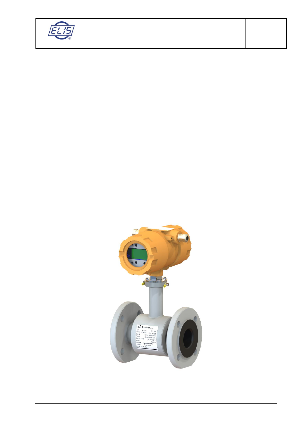
Electromagnetic flowmeters of the type series FLONET FH30xx (for normal operating environment) and
FLONEX FXx11x (for explosive atmospheres) are meters intended for bi-directional measurement of
volume flow rates of conductive liquids in a fully flooded piping. The flow velocity range is 0.025 –10m/s
and the minimum conductivity of the measured fluid is 10 μS/cm, for de-mineralised water 20 μS/cm.
This manual contains a detailed description of the meter commissioning procedure and instructions for
meter control on the user level.
The flowmeters are supplied verified as to their functions, calibrated and with the output parameters set
according to the order number specifications and other customer requirements (if any).
Instructions regarding the order number specifications can be found in the meter manuals supplied with the
products:
Electromagnetic flowmeter FLONET FH30xx –section 15
Electromagnetic flowmeter for application in explosive atmospheres FLONEX FXx11x –section 15
Information on the meter parameter setting is included in the delivery note of every
flowmeter.
Provided the meter is installed on site in observance of all instructions and directions in the manual, it will
be ready for immediate operational start.
2. ASSOCIATED DOCUMENTATION
Es 90684K Communication interface RS-485 MODBUS RTU
Electromagnetic flowmeters FLONEX FXx11x and FLONET FH30xx
Es 90675K Electromagnetic flowmeters for application in explosive atmospheres FLONEX FXx11x
Es 90678K Electromagnetic flowmeter FLONET FH30xx
3. METER COMMISSIONING
Prior to connecting the meter to its power source make sure that:
The power grid supply voltage is the same as that specified on the meter rating plate;
The power grid is provided with suitable protection devices;
All terminals and electric contact elements have been properly tightened;
The connecting cables are:
ointact,
oconnected to the correct terminals on both the meter and the plant control system sides,
osecured against incidental pulling out of the bushings, and
The required meter interconnection and grounding to the reference potential have been properly done.
Apart from examination of the electric connections prior to the meter operational start, it is also important to
check:
The meter protection covers;
The meter installation details with respect to the co-operating technology; and
The operational conditions of the meter.
The meter sensor shall be fully flooded with the measured liquid.
More detailed description of the required initial inspection procedure is included in the flowmeter manual.
ELIS PLZEŇ a. s.
Project design, installation and service manual
Page 5 of33
Electromagnetic flowmeters of the type series
FLONEX FXx11x and FLONET FH30xx
Meter control instructions
ELIS PLZEŇa. s., Lucni 425/15, 301 00 Plzeň, Czech Republic tel.:+420 377 517 711, fax:+420 377 517 722 Es 90 686 K
4. METER ENERGISING
4.1. Initial display status
Upon connecting the power supply to the meter, all its modules will undergo an initialisation procedure.
Following the display unit test, the basic screen format will appear on the display including information on:
Current volume flow rate measured by the meter
(if an error is indicated, its code will be shown next to the flow rate figure)
Aggregate flow volume passed through the meter in the positive direction
Aggregate flow rate passed through the meter in the negative direction
Shown in the top section of the display will be a bar graph relating the current volume flow rate to the
specified maximum flow rate.
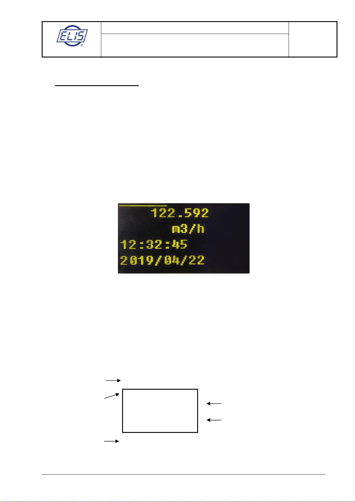
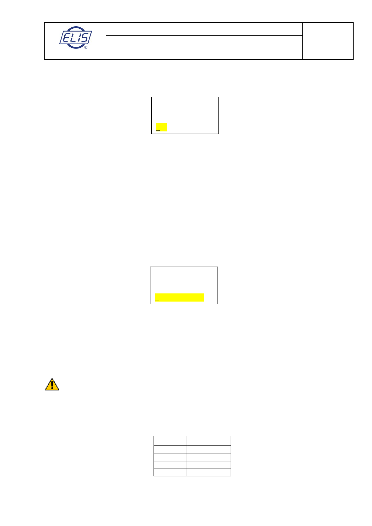
4.2. Basic screen
4.3. Front panel and control buttons
4.3.1. Display unit
The flowmeter includes a colour OLED display of 128x64 pixels providing visual information to the user on
all measured quantities, meter parameter settings and important operational information. The display
control is facilitated by four optical buttons (optical reflex sensors).
4.3.2. Control button functions
Button positions with respect to the display unit
▲►
■■■■■■■■■■■■■■■■■■■
1,025
m3/h
45,34
- 25,1
m3
ESC
ENTER
3
2
1
4
1

ELIS PLZEŇ a. s.
Project design, installation and service manual
Page 6 of33
Electromagnetic flowmeters of the type series
FLONEX FXx11x and FLONET FH30xx
Meter control instructions
ELIS PLZEŇa. s., Lucni 425/15, 301 00 Plzeň, Czech Republic tel.:+420 377 517 711, fax:+420 377 517 722 Es 90 686 K
Explanation:
1 … optical buttons (optical reflex sensors)
2 … current /instantaneous flow rate
3 … selected item from MENU –DISPLAY, or error message
4 … current/instantaneous flor rate –bar graph
Control button functions
Buttons ▲, ►, ENTER are activated by a short touch with a finger.
Button ESC is activated by either a short (0.3s) or longer touch (> 2s).
▲Move in a menu to the text item upwards
Cyclic functions: setting numeric values 0–9 (towards higher values)
Change in sign +/−
►Move in a menu to the next item downwards
Cursor position control in setting numeric values
ENTER Confirmation of selected operation
ESC Departure from current operation to the previous menu item with no change
ESC 2 s Finger touch longer than 2s: return to the basic screen
Actuated (by a finger touch) can be just one button at a time while the remaining buttons shall be
left uncovered. For repeated button actuation remove the finger and touch the button again.
5. FLOWMETER CONTROL
5.1. Manual control
Manual meter control and selection of menu items using optical buttons do not require any special skills;
these functions are intuitive and user friendly.
5.1.1. Basic screen
Basic screen always shows information on current / instantaneous flow rate (lines 1 and 2).
The remaining two lines are reserved for supplementary data the user may select from the menu Display.
The meter is supplied with these two lines pre-set to show the aggregate flow volumes passed through the
meter sensor in the positive and negative directions. The volume figure alternates with the selected volume
unit.
Should the flowmeter identify a condition that might adversely affect the meter functions, next to the
magnitude of the instantaneous flow rate on line 1 will appear the respective error code. In cases of a
major error that might significantly affect the measurement precision, displayed in the data field reserved
for the flow rate data will be a zero. This applies to situations such as ADC failure, open or short-circuited
excitation, not fully flooded piping, strong electromagnetic interference and others.
Flow volume data shown
in turns with volume unit
1,025
m3/h
45,342585
−25,125486
ELIS PLZEŇ a. s.
Project design, installation and service manual
Page 7 of33
Electromagnetic flowmeters of the type series
FLONEX FXx11x and FLONET FH30xx
Meter control instructions
ELIS PLZEŇa. s., Lucni 425/15, 301 00 Plzeň, Czech Republic tel.:+420 377 517 711, fax:+420 377 517 722 Es 90 686 K
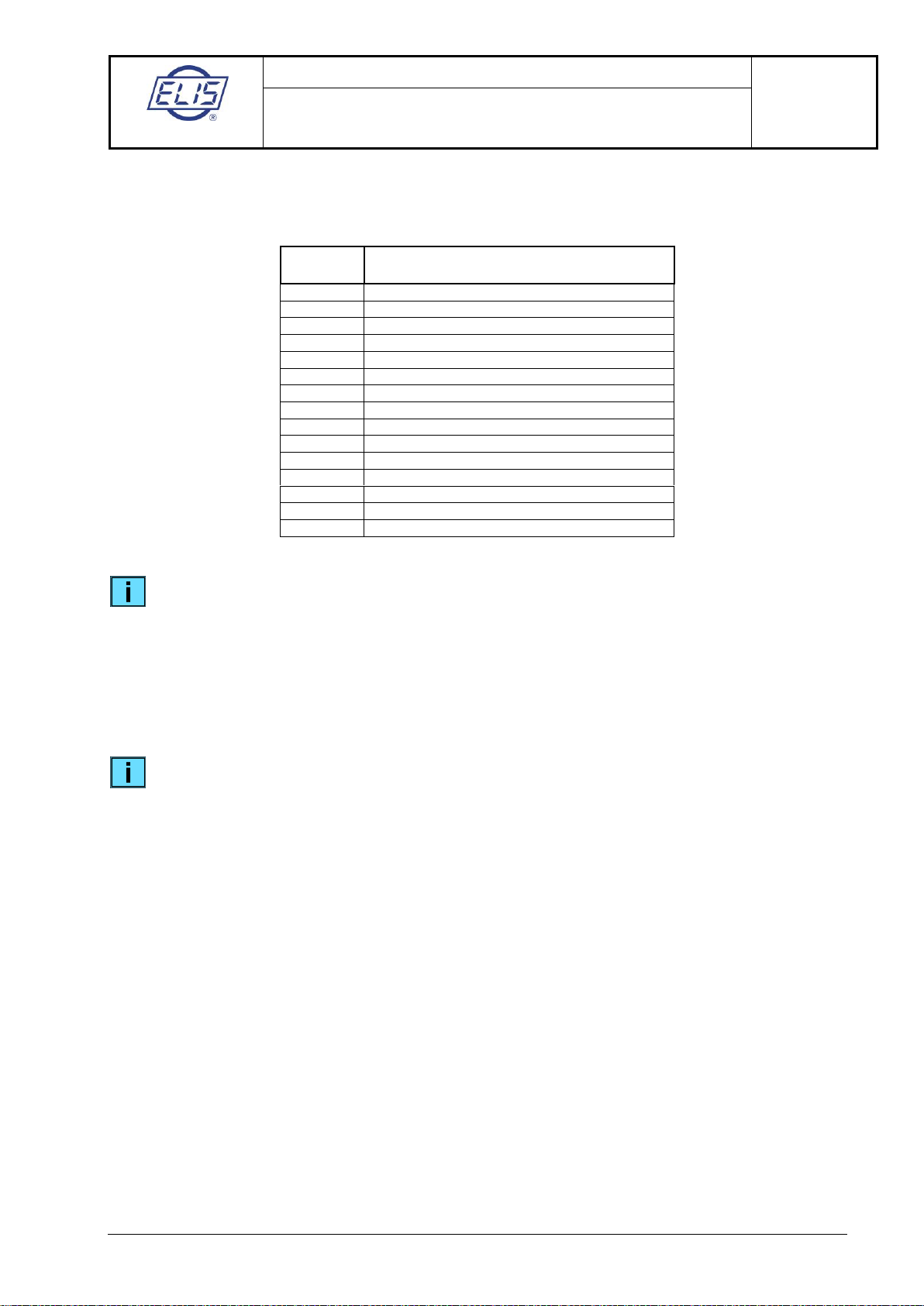
5.1.2. Error and diagnostic messages
Error
code
Description
E00
No error
E01
ADC overflow condition
E02
Fast flow-rate changes
E03
Memory write or read error
E04
Another electronic unit error
E05
Warning: zero flow rate calibration impossible
E06
Low excitation current
E07
Short-circuited coils
E08
Information: calibration in progress
E09
Empty piping
E10
OUT1 error
E11
OUT2 error
E12
Information: IOUT outside permitted range
E13
Incorrect time setting
E14
Q4 exceeded
As long as you move in the control or parameter-setting menus, the display remains in the
active mode (backlighted).
The backlighting time can be set in the menu item Backlighting time. Deactivated display will
automatically be activated upon touching any control button.
5.1.3. User password
To enter Main menu from Basic screen, actuate the ESC 2 s button and specify your user password.
The initial user password is pre-set in production at 0000.
The user password can only be changed using the FLOSET 4.0 program via communication line
RS-485 MODBUS RTU.
Should no control button (▲, ►, ESC, ENTER) be actuated during the recent three minutes, or should the
specified backlighting time elapse before that, the display will return automatically to the Basic screen
format.
ELIS PLZEŇ a. s.
Project design, installation and service manual
Page 8 of33
Electromagnetic flowmeters of the type series
FLONEX FXx11x and FLONET FH30xx
Meter control instructions
ELIS PLZEŇa. s., Lucni 425/15, 301 00 Plzeň, Czech Republic tel.:+420 377 517 711, fax:+420 377 517 722 Es 90 686 K
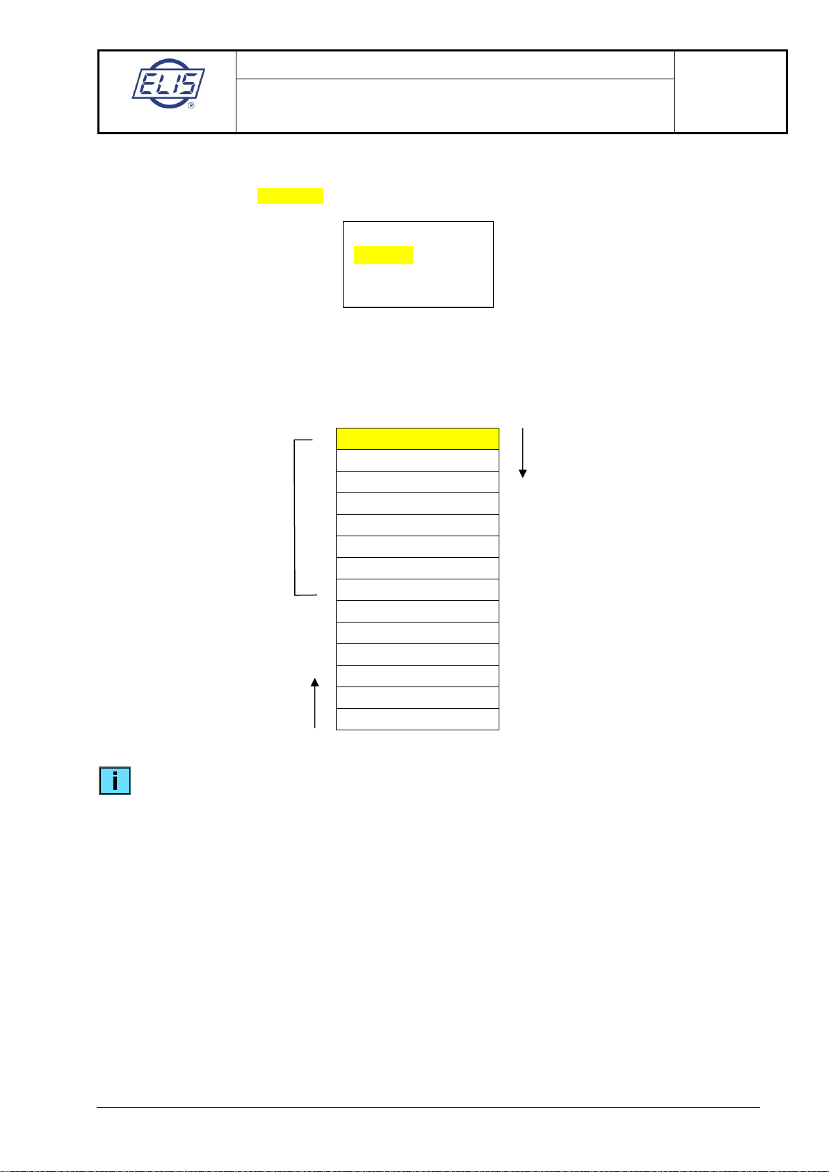
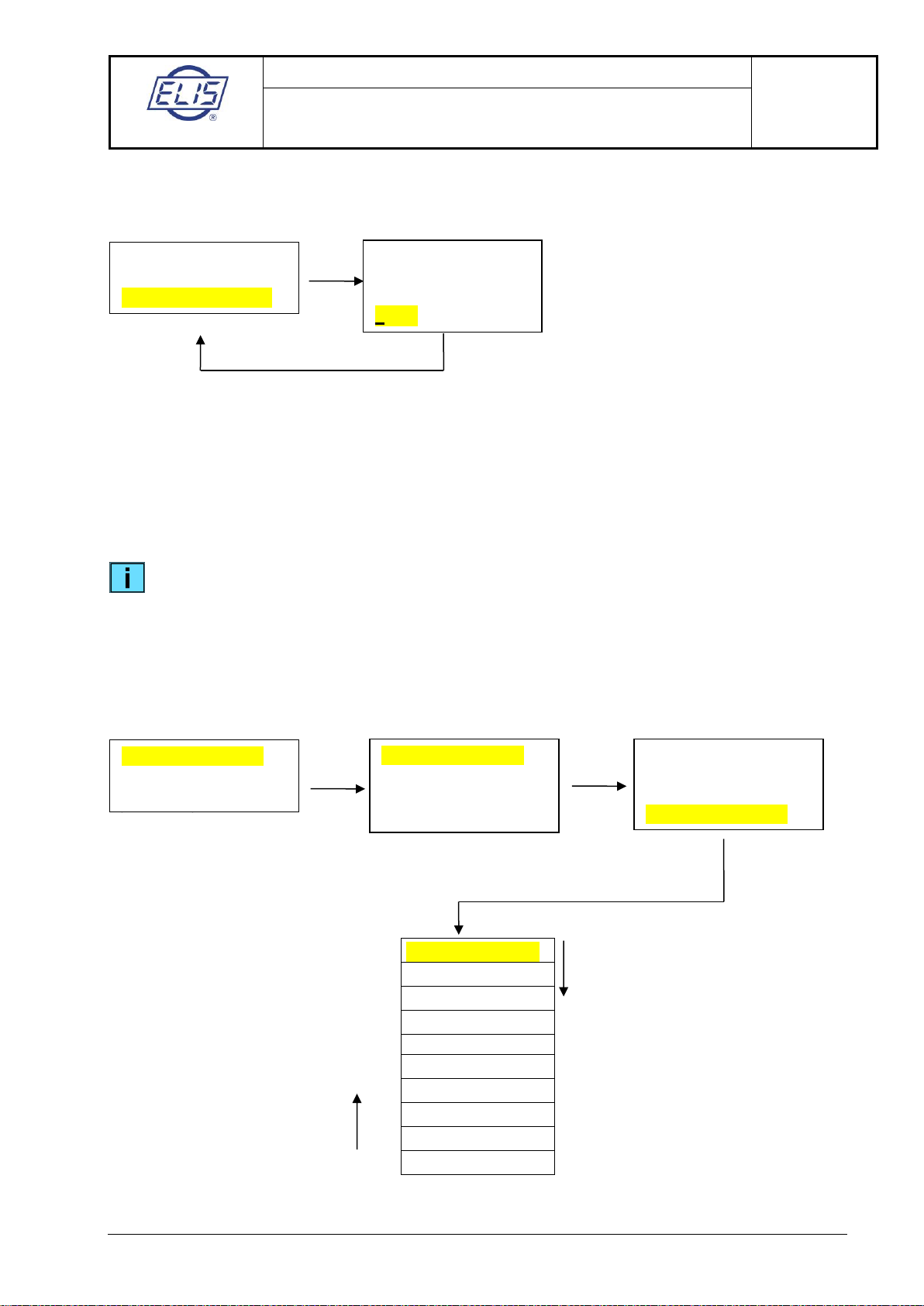
5.1.4. Main menu
There are only four lines shown on the flowmeter display. Upon the first call on Main menu, the following
items will appear with the Language item highlighted.
The highlighted item can be selected using the ENTER command.
Return to Basic screen: ESC 2 s
Use buttons ► and ▲to scroll in the menu.
Language
Display data
Analog output
Output functions
Serial line
Date setting
Time setting
Volume resetting
Number of samples
Suppressed flow rate
Zero setting
Manufacturing data
Production setting
Simulation mode
The manufacturer supplies the flowmeter verified as to its functions, calibrated and with parameters
set according to the customer’s order. When installed in the user’s technology in observance of the
requirements specified in the product manual, the flowmeter will be ready for immediate
operational start.
In cases where the user requires an accelerated procedure for the meter commissioning and the
meter parameter setting with respect to the given operational conditions and the co-operating
higher-level (plant) control system, it suffices to set the parameters shown in bold print in the above
list of the Main menu items.
To move downward in the menu, use
button ►
To move upward in the menu,
use button ▲
Fast meter operational start
Flow simulation
Language
Displayed data
Analog output
ELIS PLZEŇ a. s.
Project design, installation and service manual
Page 9 of33
Electromagnetic flowmeters of the type series
FLONEX FXx11x and FLONET FH30xx
Meter control instructions
ELIS PLZEŇa. s., Lucni 425/15, 301 00 Plzeň, Czech Republic tel.:+420 377 517 711, fax:+420 377 517 722 Es 90 686 K
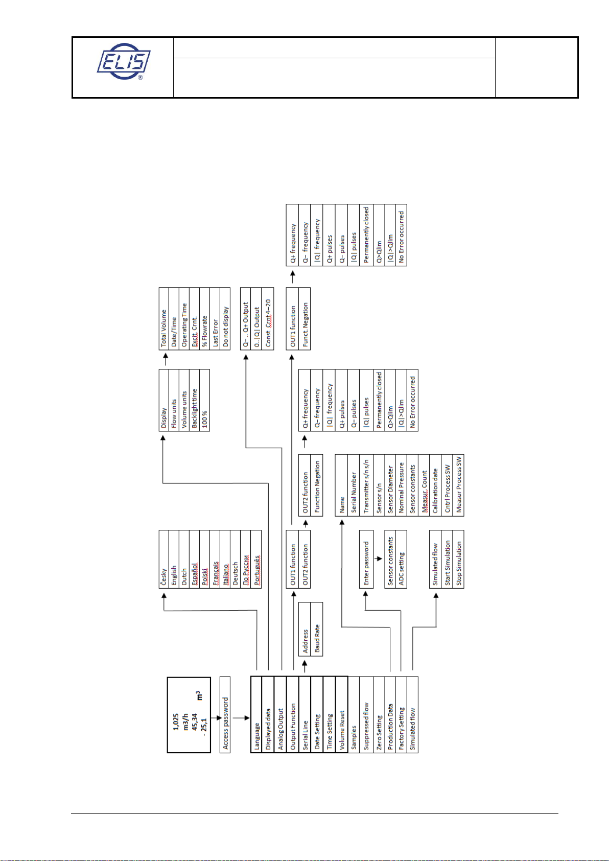
Control menu structure of flowmeters FLONEX FXx11x and FLONET FH30xx

ELIS PLZEŇ a. s.
Project design, installation and service manual
Page 10 of33
Electromagnetic flowmeters of the type series
FLONEX FXx11x and FLONET FH30xx
Meter control instructions
ELIS PLZEŇa. s., Lucni 425/15, 301 00 Plzeň, Czech Republic tel.:+420 377 517 711, fax:+420 377 517 722 Es 90 686 K
5.1.4.1. Language
English
Česky
Dutch
Español
Polski
Français
Italiano
Deutsch
По Русски
Português
The item selected by buttons ► and ▲ will be highlighted. Confirm the selection by ENTER whereby the
display will return to the previous item on the Main menu.
Return to Basic screen: ESC 2 s
The item selection procedure can be interrupted at any time by actuating button ESC with no effect
on the original setting. The display will then return to the previous screen format with item
Language highlighted. The interrupt function of the ESC button applies to all parameter setting
procedures.
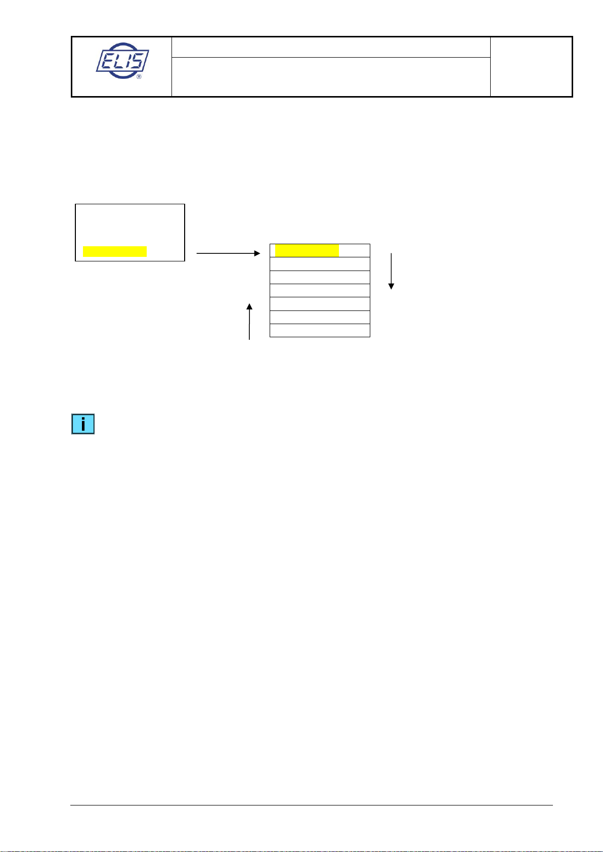
5.1.4.2. Display data
The selected item will be highlighted and can be open using ENTER.
Display data
Flow-rate units
Volume units
Backlighting time
100%
To move upward in the menu,
use button ▲
To move downward in the menu, use
button ►
Language
English
ENTER
To move downward in the menu, use
button ►
To move upward in the menu,
use button ▲
ELIS PLZEŇ a. s.
Project design, installation and service manual
Page 11 of33
Electromagnetic flowmeters of the type series
FLONEX FXx11x and FLONET FH30xx
Meter control instructions
ELIS PLZEŇa. s., Lucni 425/15, 301 00 Plzeň, Czech Republic tel.:+420 377 517 711, fax:+420 377 517 722 Es 90 686 K
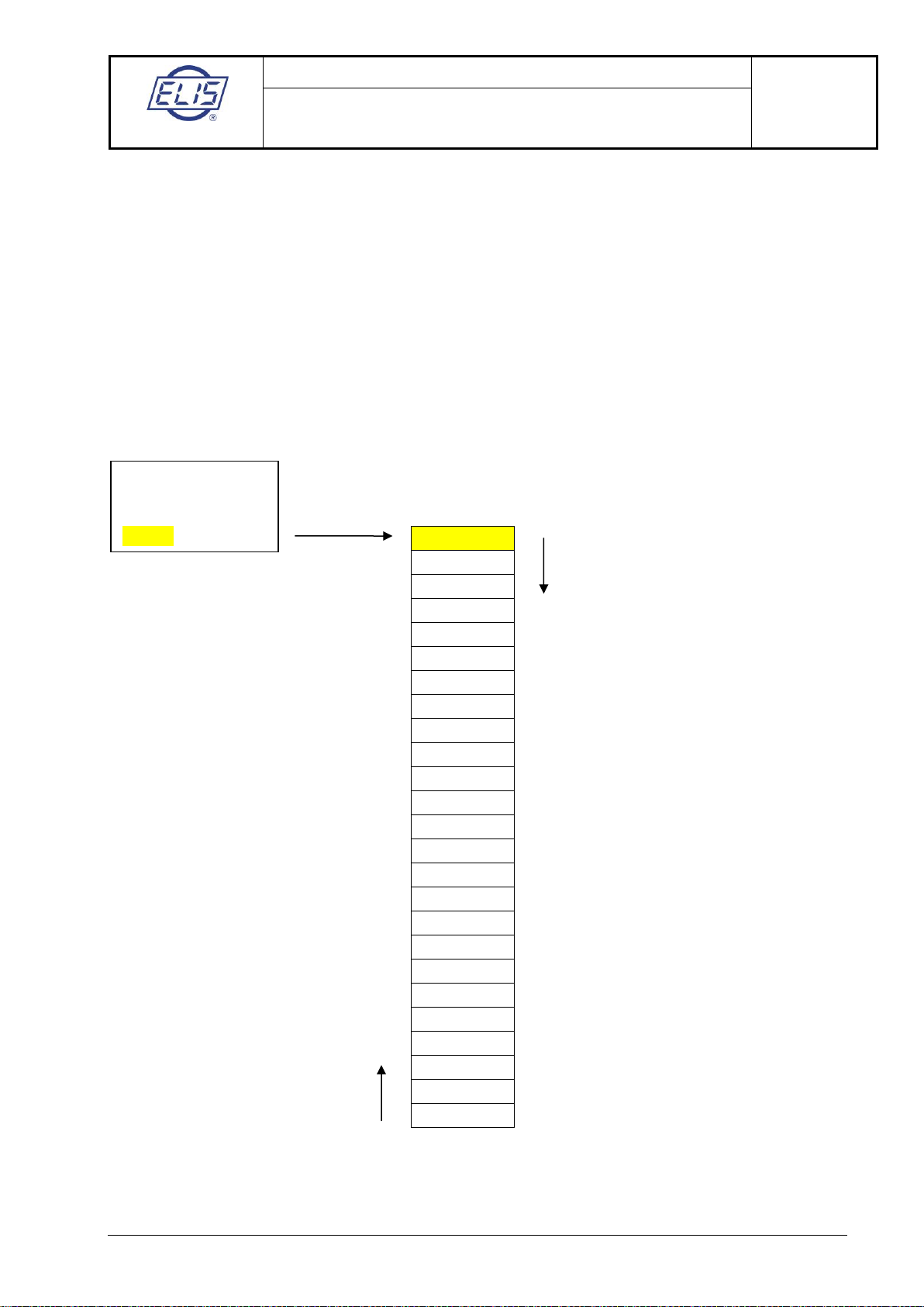
5.1.4.2.1. Display data
Upon selecting the Display data item, the user may pick out supplementary data to be shown on the
display lines 3 and 4. In Basic screen, these appear under the data on current/instantaneous flow rate. The
initial setting consists of the data on the aggregate flow volume passed through the meter sensor in the
positive and negative directions.
The item selected by buttons ► and ▲ will be highlighted (in yellow). Confirm the selection by ENTER, the
display will then return to the previous menu item. The selected item will appear on line four in Basic
screen. Displayed can only be one item at a time.
Upon selecting the No display item, Basic screen will only show the instantaneous flow rate data
(line 1 … flow rate, line 2 … flow rate units).
5.1.4.2.1.1 Volume Q+ a Q−
Alternated (cyclic) display of current flow volume and the selected volume unit:
Display line 3: aggregate flow volume passed through the meter in positive direction
Display line 4: aggregate flow volume passed through the meter in negative direction
5.1.4.2.1.2 Time and date
Display line 3: time
Display line 4: date
5.1.4.2.1.3 Working time and error time
Display line 3: measurement down time due to meter error (Error time)
Display line 4: aggregate operating time (Working time) including Error time
5.1.4.2.1.4 Excitation current
Display line 3: current flowing through the sensor excitation coils (typically 200mA)
Display line 4: resistance of the fluid between the measuring electrodes (kΩ). This information is
used to check the condition of fully flooded piping.
5.1.4.2.1.5 Flow rate per cent
Display line 3: measured flow rate in per cent of the maximum flow rate
Display line 4: the character of %
Total volume
Date/time
Working time
Excitation current
Flow rate per cent
Last error
No display
Display data
Total volume
To move downward in the menu, use
button ►
ENTER
To move upward in the menu,
use button ▲
ELIS PLZEŇ a. s.
Project design, installation and service manual
Page 12 of33
Electromagnetic flowmeters of the type series
FLONEX FXx11x and FLONET FH30xx
Meter control instructions
ELIS PLZEŇa. s., Lucni 425/15, 301 00 Plzeň, Czech Republic tel.:+420 377 517 711, fax:+420 377 517 722 Es 90 686 K
5.1.4.2.1.6 Last error
Cyclic display of the error code and error description vs. time and date of the error incidence:
Display line 3: error code (Exx) / time
Display line 4: error description / date
5.1.4.2.1.7 No display
Display line 3: empty
Display line 4: empty
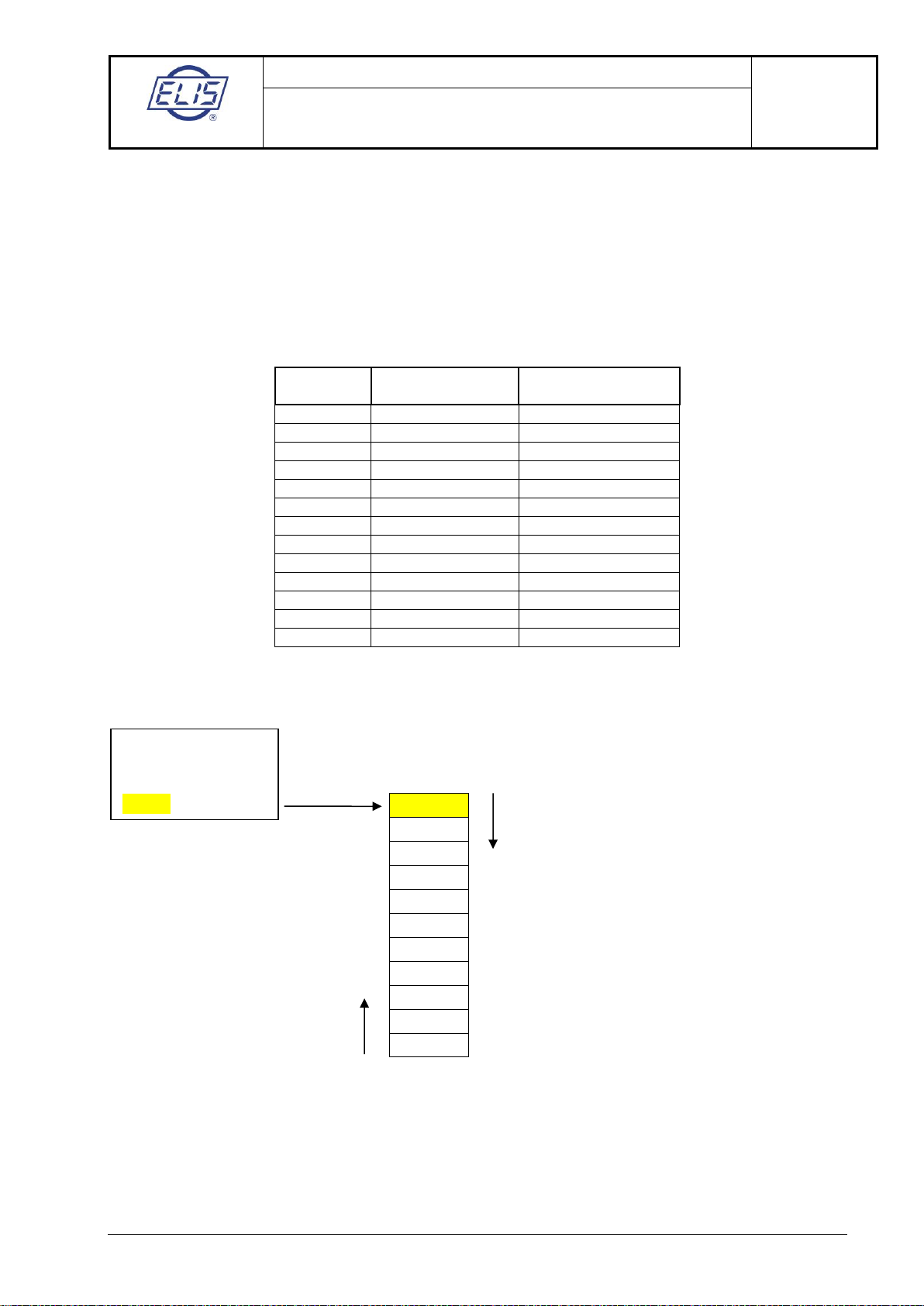
5.1.4.2.2. Flow rate units
l/s
l/min
l/h
Mil L/day
m3/s
m3/min
m3/h
m3/day
ft3/s
ft3/min
ft3/h
ft3/day
gal/s
gal/min
gal/h
gal/day
Mil Gal/day
bbl/s
bbl/min
bbl/h
bbl/day
ImpGal/s
ImpGal/min
ImpGal/h
ImpGal/day
Flow rate units
ft3/min
To move downward in the menu, use
button ►
ENTER
To move upward in the menu,
use button ▲
ELIS PLZEŇ a. s.
Project design, installation and service manual
Page 13 of33
Electromagnetic flowmeters of the type series
FLONEX FXx11x and FLONET FH30xx
Meter control instructions
ELIS PLZEŇa. s., Lucni 425/15, 301 00 Plzeň, Czech Republic tel.:+420 377 517 711, fax:+420 377 517 722 Es 90 686 K
The item selected by buttons ► and ▲ will be highlighted (in yellow). Confirm the selection by ENTER
whereby the menu will return to the previous item (Flow rate units).
The selected flow-rate unit will appear on line 2 in the Basic screen.
Return to Main menu: 1 x ESC
Return to Basic screen: ESC 2 s
Conversion of various fluid volume units to litres
Unit
designation
Name
Volume in litres
l
litre
1.00000
hl
hectolitre
100.00000
m3
cubic meter
1,000.00000
Mil L
million litres
1,000,000.00000
ft3
cubic foot
28.31685
gal
US gallon
3.78540
MilGal
million US gallons
3,785,412.00000
bbl
US barrel
158.98729
ImpGal
UK gallon
4.54609
bush
bushel
35.23907
yd3
cubic yard
764.55487
in3
cubic inch
0.01638
bblLiq
US barrel liquid
119.240471
5.1.4.2.3. Volume units
The item selected by buttons ► and ▲ will be highlighted (in yellow). Confirm the selection by ENTER
whereby the menu will return to the previous item (Volume units).
The selected fluid volume unit will appear in Basic screen.
Return to Main menu: 1x ESC
Return to Basic screen: ESC 2 s
l
ImpGal
m3
bbl
bush
yd3
ft3
in3
bblLiq
hl
gal
Volume units
l (litre)
To move downward in the menu, use
button ►
To move upward in the menu,
use button ▲
ENTER
ELIS PLZEŇ a. s.
Project design, installation and service manual
Page 14 of33
Electromagnetic flowmeters of the type series
FLONEX FXx11x and FLONET FH30xx
Meter control instructions
ELIS PLZEŇa. s., Lucni 425/15, 301 00 Plzeň, Czech Republic tel.:+420 377 517 711, fax:+420 377 517 722 Es 90 686 K
5.1.4.2.4. Backlighting time
Setting range: 0 to 999s
Value 0 is reserved for unlimited backlighting time.
The flashing underline marker shows the digital position ready to be set.
Set the display backlighting time using buttons ► and ▲and confirm the setting by actuating the ENTER
button. The display will return to the previous menu item (Backlighting time).
Return to Main menu: 1 x ESC
Return to Basic screen: ESC 2 s
To actuate the “sleeping” display, depress any of the four control buttons.
5.1.4.2.5. 100%
By selecting the 100% item, the user may define the flow rate to which the instantaneous flow rates will be
related (in per cent); the same applies to the bar graph display.
The flashing underline marker shows the digital position ready to be set.
Using buttons ► and ▲, set the flow-rate value in litres per second corresponding to the intended
maximum (100%) flow rate. Use button ►to move the position marker, and button ▲to set the numeric
value 0 to 9. Confirm the setting by depressing the ENTER button. The display will then return to the
previous menu item (100%).
Return to Main menu: 1 x ESC
Return to Basic screen: ESC 2 s
The maximum flow rate value shall always be set in litres per second irrespective of the
currently used flow rate unit. The flow rate value set as 100% shall not, in consideration of
the meter sensor size, correspond to the fluid flow velocity in excess of 10 meters per
second. It is recommended to set the maximum flow rate corresponding to the fluid flow
velocity between 3 and 5 m/s.
Volume flow rates in litres per second corresponding to various flow rate units
Unit
(litres per sec.)
l/s
1.000000E+00
l/min
1.666667E-02
l/h
2.777778E-04
Mil L/day
1.157407E+01
Backlighting time
s
000
100%
l/s
+1.000000E+01

ELIS PLZEŇ a. s.
Project design, installation and service manual
Page 15 of33
Electromagnetic flowmeters of the type series
FLONEX FXx11x and FLONET FH30xx
Meter control instructions
ELIS PLZEŇa. s., Lucni 425/15, 301 00 Plzeň, Czech Republic tel.:+420 377 517 711, fax:+420 377 517 722 Es 90 686 K
Example:
A user has selected for display of instantaneous flow rate values the unit of m3/hour and wishes to set the
100% flow rate value at 150 m3/hour.
The above table gives the conversion coefficient between 1 m3/hour and litres per second 2.777778E-01.
The value to be set as the menu item 100% therefore is:
150 x 2.777778E-01 = 4.1666666E+01 (l/s).
5.1.4.3. Analog output
(passive, current)
5.1.4.3.1. Output for Q−… Q+
m3/s
1.000000E+03
m3/min
1.666667E+01
m3/h
2.777778E-01
m3/day
1.157407E-02
ft3/s
2.831685E+01
ft3/min
4.719474E-01
ft3/h
7.865791E-03
ft3/day
3.277413E-04
gal/s
3.785412E+00
gal/min
6.309020E-02
gal/h
1.051503E-03
gal/day
4.381264E-05
Mil Gal/day
4.381264E+01
bbl/s
1.589873E+02
bbl/min
2.649788E+00
bbl/h
4.416314E-02
bbl/day
1.840131E-03
ImpGal/s
4.546090E+00
ImpGal/min
7.576817E-02
ImpGal/h
1.262803E-03
ImpGal/day
5.261678E-05
Output Q− .. Q+
Output 0 .. |Q|
Fixed current 4 . 20
Flow rate for 20mA
Flow rate for 4mA
Flow rate for 20mA
Output Q− .. Q+
l/s
+1.000000E+00
Flow rate for 20mA
Flow rate for 4mA
Flow rate for 4mA
Output Q− .. Q+
l/s
+1.000000E+00
ENTER
ENTER
ENTER
►▲
ENTER
ENTER

ELIS PLZEŇ a. s.
Project design, installation and service manual
Page 16 of33
Electromagnetic flowmeters of the type series
FLONEX FXx11x and FLONET FH30xx
Meter control instructions
ELIS PLZEŇa. s., Lucni 425/15, 301 00 Plzeň, Czech Republic tel.:+420 377 517 711, fax:+420 377 517 722 Es 90 686 K
The flashing underline marker shows the digital position ready to be set.
Using buttons ► and ▲, set the flow-rate value in litres per second corresponding to current values 4 and
20mA. Confirm the setting by depressing the ENTER button. The display will then return to the previous
menu item (Flow rate for 20mA / Flow rate for 4mA).
Return to Main menu: 2 x ESC
Return to Basic screen: ESC 2 s
The flow rate values set for current levels 4 or 20mA shall always be in litres per second.
The values of flow rate for currents 4 and 20mA can be both positive and negative, and each such
value can be greater or smaller than the other. Theoretically there can be up to six different
relationships between the output current (IOUT) and the flow rate (Q).
Output current for flow rate ranging from Q− to Q+
5.1.4.3.2. Output for 0 ... |Q|
Current for |Q|
The setting procedure is essentially the same as that described for Analog output Q− ... Q+.The only
value to be set here is the flow rate corresponding to output current 20mA.
ELIS PLZEŇ a. s.
Project design, installation and service manual
Page 17 of33
Electromagnetic flowmeters of the type series
FLONEX FXx11x and FLONET FH30xx
Meter control instructions
ELIS PLZEŇa. s., Lucni 425/15, 301 00 Plzeň, Czech Republic tel.:+420 377 517 711, fax:+420 377 517 722 Es 90 686 K
5.1.4.3.3. Fixed current 4–20 mA
The flashing underline marker shows the digital position ready to be set.
Using buttons ► and ▲, set the highlighted current value in the range of 4 to 20mA. Confirm the setting by
depressing the ENTER button. The display will return to the previous menu item (Fixed current 4–20).
From that moment on the analog output is operated in the mode of fixed current. Return to the measuring
mode via setting the function of analog output.
Return to Main menu: 1 x ESC
Return to Basic screen: ESC 2 s
The value of fixed current can only be set within the range of 4.00 to 20.00mA. Values outside this
range will not be accepted; in that case, upon depressing button ENTER, the display will remain in
the mode of current setting and will not return to menu item Fixed current 4–20.
5.1.4.4. Output functions
(passive, open collector)
The parameter setting procedures for Output 1 functions and Output 2 functions are the same.
Výěr položky
Function selection by buttons ► and ▲
Frequency for Q+
Frequency for Q−
Frequency for |Q|
Impulses for Q+
Impulses for Q−
Impulses for |Q|
Constantly closed
Q>Qlim
|Q|>Qlim
No error
Output Q− .. Q+
Output 0 .. |Q|
Fixed current 4–20
Output 1 function
Function negation
Output 1 function
Frequency for Q+
Output 1 function
Output 2 function
ENTER
Fixed current 4–20
mA
10.00
14.00
ENTER
ENTER
To move downward in the menu, use
button ►
To move upward in the menu,
use button ▲
ENTER

ELIS PLZEŇ a. s.
Project design, installation and service manual
Page 18 of33
Electromagnetic flowmeters of the type series
FLONEX FXx11x and FLONET FH30xx
Meter control instructions
ELIS PLZEŇa. s., Lucni 425/15, 301 00 Plzeň, Czech Republic tel.:+420 377 517 711, fax:+420 377 517 722 Es 90 686 K
The function selected by buttons ► and ▲will appear backlighted in yellow on the last display line.
Confirm the selected by ENTER.
Upon selection of item Function negation the output signal will change sign. The other functions
of the multi-function output will remain as they are.
5.1.4.4.1. Frequency for Q+
Using buttons ► and ▲, set the flow rate in litres per second corresponding to the output frequency of
1kHz. Confirm the set value by ENTER.The display will return to the previous menu item (Flow rate at
1kHz).
Return to Main menu: 3 x ESC
Return to Basic screen: ESC 2 s
The flow rate value Q+ for 1kHz shall always be set in litres per second. Conversion of the volume
flow rate in litres per second to flow rates in other units is described above in the procedure for
setting the 100% value.
5.1.4.4.2. Frequency for Q−
See the procedure for setting the frequency for Q+.
5.1.4.4.3. Frequency for |Q|
See the procedure for setting the frequency for Q+.
Output 1 function
Frequency for Q+
Flow rate at 1kHz
Flow rate at 1kHz
l/s
+ 1 . 000000E+00
ENTER
ENTER
ENTER
ELIS PLZEŇ a. s.
Project design, installation and service manual
Page 19 of33
Electromagnetic flowmeters of the type series
FLONEX FXx11x and FLONET FH30xx
Meter control instructions
ELIS PLZEŇa. s., Lucni 425/15, 301 00 Plzeň, Czech Republic tel.:+420 377 517 711, fax:+420 377 517 722 Es 90 686 K
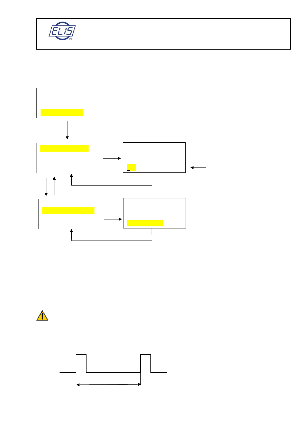
5.1.4.4.4. Impulses for Q+
Using buttons ► and ▲, set the required impulse parameters.
Confirm the setting by ENTER. The display will return to the previous menu item Impulse width / Volume
per impulse.
Return to Main menu: 3 x ESC
Return to Basic screen: ESC 2 s
Impulse number determination
The values of fluid volume per impulse (the impulse number) shall always be specified in litres per second.
The limiting conditions for impulse output parameters:
The maximum frequency of impulse output: fmax = 100Hz
The idle period between impulses Mshall be equal to or wider than the impulse width P.
Breaching this condition will result in an error message (E10, E11).
For impulse width it holds:
M
P
M
P
T
Output 1 function
Impulses for Q+
Impulse [1] length
Volume per imp. [1]
Impulse [1] width
Volume per imp. [1]
Impulse [1] width
ms
040
Volume per imp. [1]
l
+1.000000E + 00
ENTER
ENTER
ENTER
ENTER
►▲
ENTER
Setting range: 1 –999ms

ELIS PLZEŇ a. s.
Project design, installation and service manual
Page 20 of33
Electromagnetic flowmeters of the type series
FLONEX FXx11x and FLONET FH30xx
Meter control instructions
ELIS PLZEŇa. s., Lucni 425/15, 301 00 Plzeň, Czech Republic tel.:+420 377 517 711, fax:+420 377 517 722 Es 90 686 K
In selecting the impulse number, the following conditions shall be met:
Qmax
≤
3.6 × V × fmax
(m3/h, l/imp, imp/s)
Where: Q… fluid flow rate (m3/hour)
V… fluid volume per impulse (l)
P… impulse width (s)
f … impulse output frequency (Hz)
T… cycle length (s)
Volume Vper impulse is usually selected from the options shown in the following table:
V (l)
0.001
0.01
0.1
1
10
100
1,000
10,000
In cases of electronic determination of the fluid volume passed through the sensor, the impulse
width is recommended to be set at Pmin= 5ms, which meets the condition for fmax at the impulse
output equal to 100Hz. In cases of electro-mechanical counters, Pmin is usually set at 50ms,
corresponding to the maximum frequency at the impulse output of 10Hz.
Example:
Assume that a user specified for their flowmeter of DN100 the maximum operating flow rate:
Qmax = 150 m3/h (Qmax = 41.66 l/s … v = 5.3 m/s)
For the fluid volume corresponding to one impulse (of length 5ms, fmax 100Hz) it holds:
By selecting the next higher impulse number from the above table (1 litre per impulse) the user will make
sure that the impulse output frequency will not exceed (for the specified Qmax of 150 m3/hour) the value of
100Hz and, at the same time, verify the selection of the impulse length (5ms). The user may choose the V
values other than those from the basic selection in the above table, e.g. 0.5 litres/impulse.
Should the volume flow rate and the aggregate volume passed through the meter be given in units
outside the SI system (e.g. US gallons), the fluid volume per impulse should be converted to litres
using the table in section 5.1.4.2.2. The parameter of fluid volume per impulse shall then be
determined with respect to the maximum frequency at the impulse output and the type of
measuring system used.
P + M = T
f =
1
T
V
Qmax
(litres/impulse, m3/h, Hz)
3.6 × fmax
V
0.416 (litres/impulse)
This manual suits for next models
1
Table of contents
Other Elis Measuring Instrument manuals


Popular Measuring Instrument manuals by other brands


PCE Instruments
PCE Instruments PCE-PHD 1 manual

Tektronix
Tektronix 7D20 Operator's manual

Tektronix
Tektronix Keithley 4200A-SCS Setup and Maintenance

Extech Instruments
Extech Instruments MA1500 user manual

Tecson
Tecson Tank-Spion Digital LX-NET installation instructions

TechnipFMC
TechnipFMC Smith Meter AccuLoad III installation manual

Stone Technologies Corporation
Stone Technologies Corporation 4110Dual Technical manual

Cygnus
Cygnus 1 Ex manual

PCE Instruments
PCE Instruments PCE-DFG N 20K user manual

Antec Scientific
Antec Scientific ROXY 210 user manual

ATAGO
ATAGO PAL- HIKARi 10 instruction manual

Midtronics
Midtronics MDX-652P instruction manual