Elis SONOELIS SE404X User manual

ELIS PLZEŇa. s.
Design, Assembly and Service Manual
Page 1 of 44
Ultrasonic flow meter SONOELIS SE404X,
SONOELIS SE406X
ELIS PLZEŇa. s., Lucni 15, P. O. BOX 126, 304 26 Plzen, Czech Republic, Phone: +420/377517711, fax: +420/377517722 Es90201K/c
Ultrasonic Flow Meters
SONOELIS SE404X,
SONOELIS SE406X

ELIS PLZEŇa. s.
Design, Assembly and Service Manual
Page 2 of 44
Ultrasonic flow meter SONOELIS SE404X,
SONOELIS SE406X
ELIS PLZEŇa. s., Lucni 15, P. O. BOX 126, 304 26 Plzen, Czech Republic, Phone: +420/377517711, fax: +420/377517722 Es90201K/c
Content
1. APPLICATION ...............................................................................................................................................4
2. FUNCTION .....................................................................................................................................................4
3. DESCRIPTION ...............................................................................................................................................5
3.1. BASIC INFORMATION.................................................................................................................................................... 5
3.2. FLOW METER DESIGN .................................................................................................................................................. 6
3.2.1. The split version............................................................................................................................................... 6
3.2.1.1. Ultrasonic sensor including terminal box................................................................................................... 6
3.2.1.2. Evaluation electronic unit .......................................................................................................................... 8
3.2.2. The compact version........................................................................................................................................ 8
3.2.3. Commercial (invoicing) meters......................................................................................................................... 9
4. SPECIFICATIONS .......................................................................................................................................10
4.1. ULTRASONIC SENSORS:NOMINAL ID, RATED AND LIMIT FLOW RATES............................................................................... 10
4.2. FLOW METERS:BASIC TECHNICAL SPECIFICATIONS ....................................................................................................... 11
4.3. SENSOR SELECTION .................................................................................................................................................. 12
4.4. COMMUNICATION INTERFACE...................................................................................................................................... 12
5. METER INSTALLATION AND APPLICATION; BASIC RULES ................................................................13
6. METER INSTALLATION GUIDE .................................................................................................................16
6.1. ELECTRONIC CIRCUITS (THE SPLIT VERSION)................................................................................................................ 16
6.2. ELECTRICAL CONNECTIONS........................................................................................................................................ 17
6.3. ULTRASONIC SENSOR................................................................................................................................................ 19
6.4. MECHANICAL ASSEMBLY AND INSTALLATION................................................................................................................. 19
7. METER COMMISSIONING AND CONTROL ..............................................................................................19
7.1. THE ECONOMIC CONFIGURATION ............................................................................................................................ 19
7.2. THE STANDARD CONFIGURATION ............................................................................................................................ 19
7.2.1. Display data ................................................................................................................................................... 20
7.2.1.1. Meter status information ......................................................................................................................... 20
7.2.1.2. Display of measured data ....................................................................................................................... 20
7.2.2. Review of the measured quantities ................................................................................................................ 20
7.2.3. Review of the measured quantity units........................................................................................................... 21
7.2.4. Unit conversion table...................................................................................................................................... 22
7.3. THE COMFORT CONFIGURATION.............................................................................................................................. 22
7.3.1. Data display mode.......................................................................................................................................... 23
7.3.1.1. Volume flow rate ..................................................................................................................................... 23
7.3.1.2. Relative volume flow rate........................................................................................................................ 23
7.3.1.3. Mass flow rate......................................................................................................................................... 23
7.3.1.4. Relative mass flow rate........................................................................................................................... 23
7.3.1.5. Volume.................................................................................................................................................... 23
7.3.1.6. Volume +................................................................................................................................................. 23
7.3.1.7. Volume - ................................................................................................................................................. 23
7.3.1.8. Mass ....................................................................................................................................................... 23
7.3.1.9. Mass + .................................................................................................................................................... 24
7.3.1.10. Mass - ................................................................................................................................................... 24
7.3.1.11. Temperature ......................................................................................................................................... 24
7.3.1.12. Density.................................................................................................................................................. 24
7.3.1.13. Sound propagation velocity................................................................................................................... 24
7.3.1.14. Fluid flow velocity.................................................................................................................................. 24
7.3.1.15. Start of the measurement period........................................................................................................... 24
7.3.1.16. Duration of the measurement period..................................................................................................... 24
7.3.1.17. Duration of failure condition .................................................................................................................. 24
7.3.1.18. Power failure period .............................................................................................................................. 24
7.3.1.19. Date ...................................................................................................................................................... 24
7.3.1.20. Time...................................................................................................................................................... 24
7.3.2. Parameter setting mode................................................................................................................................. 24
7.3.2.1. Password ................................................................................................................................................ 24
7.3.2.2. Meter setting procedures ........................................................................................................................ 25
7.3.2.3. Language selection................................................................................................................................. 25
7.3.2.4. Measuring unit selection ......................................................................................................................... 25
7.3.2.5. New password definition ......................................................................................................................... 26
7.3.2.6. Initial quantity selection........................................................................................................................... 26
7.3.2.7. Definition of limit values .......................................................................................................................... 26
7.3.2.8. Resetting aggregate quantities ............................................................................................................... 27

ELIS PLZEŇa. s.
Design, Assembly and Service Manual
Page 3 of 44
Ultrasonic flow meter SONOELIS SE404X,
SONOELIS SE406X
ELIS PLZEŇa. s., Lucni 15, P. O. BOX 126, 304 26 Plzen, Czech Republic, Phone: +420/377517711, fax: +420/377517722 Es90201K/c
7.3.2.9. Meter zero setting ................................................................................................................................... 27
7.3.2.10. End of parameter setting....................................................................................................................... 28
7.4. AUTOMATED METER TEST .......................................................................................................................................... 28
8. SERVICE ACTIVITIES .................................................................................................................................36
8.2. WARRANTY SERVICES ............................................................................................................................................... 37
8.2. POST-WARRANTY SERVICES....................................................................................................................................... 37
9. STANDARD TESTS.....................................................................................................................................37
10. VERIFICATION TESTS..............................................................................................................................37
11. PACKAGING..............................................................................................................................................38
12. PRODUCT ACCEPTANCE PROCEDURE................................................................................................38
13. WARRANTY CONDITIONS .......................................................................................................................38
14. PRODUCT ORDERING .............................................................................................................................38
ELIS PLZEŇa. s.
Design, Assembly and Service Manual
Page 4 of 44
Ultrasonic flow meter SONOELIS SE404X,
SONOELIS SE406X
ELIS PLZEŇa. s., Lucni 15, P. O. BOX 126, 304 26 Plzen, Czech Republic, Phone: +420/377517711, fax: +420/377517722 Es90201K/c
1. APPLICATION
Ultrasonic flow meters SONOELIS - models SE404X and SE406X can be used to measure instantaneous flow
rate, mass flow rate as well as the aggregate quantity or mass of fluid passing through the meter sensor over a
given period of time. The measurement method used allows application of the SONOELIS flow meters for a wide
range of fluid types including non-conductive and specific corrosive fluids. Therefore the flow meters can be
used to measure flow rates of water and other technological fluids, e.g. in chemical plants. The meters are
equipped with the necessary HW and SW facilitating communication with superordinated control systems.
The flow meter may include either a single-ray (UC 3.0) or a double-ray (UC 5.0) sensor. The type designations
of various meter configurations and their components are given in a table in section 3.1 below.
2. FUNCTION
The SONOELIS flow meter utilises the impulse-wave transit-time method where the fluid flow velocity is
determined from the flight time of the ultrasonic signal between two ultrasonic transducers. The flight times are
measured for both directions of the signal wave propagation (upstream and downstream) whereby any
asymmetry in the transducer positions are effectively eliminated.
The flight time of an ultrasonic wave travelling downstream the fluid flow can be determined as follows:
tl
cv
l
cs
11
1
.cos
where l is the distance between the head parts of the ultrasonic transducers [m]
c is the ultrasonic signal propagation velocity [m/s] in the flowing fluid
v is the fluid flow velocity [m/s]
l1is the aggregate thickness of the bottom parts of the transducers [m]
c1is the ultrasonic signal propagation velocity [m/s] in the transducer body material.
The flight time of an ultrasonic wave travelling upstream/downstream the fluid flow is defined by the following
formula; the difference between the “downstream “ (t1) and “upstream” (t2) flight times is given by the different
signs of the fluid flow velocity term in the fraction denominator.
For a given transducer, l1 and c1 are known constants.
The ultrasonic signal propagation velocity can be expressed as:
vv
1c. cosfor the case of downstream measurement, and
vv
2c. cosfor the case of upstream measurement.
Therefore, the difference between the velocities of ultrasonic signals travelling downstream and upstream is
proportional to the fluid flow velocity v [m/s].
The instantaneous fluid flow rate q is defined by the following formula:
tl
cv
l
cs
21
1
cos
vvv
12
2.cos

ELIS PLZEŇa. s.
Design, Assembly and Service Manual
Page 5 of 44
Ultrasonic flow meter SONOELIS SE404X,
SONOELIS SE406X
ELIS PLZEŇa. s., Lucni 15, P. O. BOX 126, 304 26 Plzen, Czech Republic, Phone: +420/377517711, fax: +420/377517722 Es90201K/c
where v is the fluid velocity [m/s]
s is the effective cross-section of the flow meter sensor [m2], and
k(v) is a correction coefficient the magnitude of which depends on the fluid velocity.
This coefficient reflects the varying fluid velocity profile in the hydraulic section of the flow meter.
3. DESCRIPTION
3.1. Basic information
Ultrasonic flow meters SONOELIS SE404X and SE406X are electronic devices designed for measurement of
fluid flow parameters in a piping completely filled with the flowing fluid. The meter consists of a fluid flow sensor
(UC 3.0 or UC 5.0) and an evaluation electronic unit. These two parts can either be separated or designed as a
compact unit. While UC 3.0 includes two ultrasonic transducers (a single-ray sensor), UC 5.0 is a double-ray
sensor including four transducers. Sensor UC 5.0 provides for better coverage of the fluid velocity profile under a
wide range of operational conditions, in particular with low fluid flow velocities where various irregularities in the
velocity profile may occur. The application of this sensor extends the range of measured values, allows for
shorter fluid-flow stabilisation piping sections at the meter input and output and generally increases the
measurement accuracy.
In the case of a split version of the meter (with separate sensor and the associated electronic unit), the sensor is
connected to the electronic unit by two (or four) co-axial cables of adequate length. Both “compact” and “split”
versions of the meter are available in the following configurations:
ECONOMIC a basic version of a fluid flow-rate meter providing for conversion of the measured physical
quantities to electric signals.
STANDARD as the ECONOMIC model, plus an LC display with optional readings of the instantaneous
flow-rate or of the aggregate fluid-volume values. If made complete with a Pt 100
temperature sensor, the fluid temperature and fluid mass measurements and readings may
be obtained.
COMFORT as the STANDARD model, plus a panel with four push-buttons facilitating access to the user
meter-control menu and functions.
Type and model designations of flow meters and their components
qsk msvv 3/
D e s i g n a t i o n
Evaluation electronic
unit configuration
System
configuration Meter
model
Evaluation
electronic unit
(compact version)
Evaluation
electronic unit
(split version)
Flow sensor
ECONOMIC SE4040 UP 2.00 - UC 3.0
SE4041 - UP 2.10 Basic
SE4060 UP 2.00 - UC 5.0
SE4061 - UP 2.10
STANDARD SE4042 UP 4.00 - UC 3.0
SE4043 - UP 4.10 Basic + LC display
SE4062 UP 4.00 - UC 5.0
SE4063 - UP 4.10
COMFORT SE4044 UP 3.00 - UC 3.0
SE4045 - UP 3.10
Basic + LC display +
SE4064 UP 3.00 - UC 5.0 push-button control
SE4065 - UP 3.10 panel

ELIS PLZEŇa. s.
Design, Assembly and Service Manual
Page 6 of 44
Ultrasonic flow meter SONOELIS SE404X,
SONOELIS SE406X
ELIS PLZEŇa. s., Lucni 15, P. O. BOX 126, 304 26 Plzen, Czech Republic, Phone: +420/377517711, fax: +420/377517722 Es90201K/c
Regarding function, the evaluation electronic unit of the flow meter can be divided into the following sections:
- sensor isolation circuits
- sensor output switches
- ultrasonic transducer
- ultrasonic receiver including sensitivity control circuits
- interface circuits to the signal evaluation processor
- signal evaluation processor
- circuits for isolated current, frequency and impulse outputs
- serial communication line circuits
- power supply circuits.
The basic configuration of the evaluation electronic unit includes frequency and impulse outputs. All output
signals are isolated from the rest of the meter circuits.
Optional electronic accessories can further enhance the meter functions. Among these are: RS 485
communication interface, isolated current output and resistance thermometer Pt 100. The thermometer
measures the temperature of the flowing fluid and its readings can be used to convert the fluid rate and volume
data into the mass flow data. In the “split” version, the basic range of the permitted fluid temperatures can be
extended to – 20 / + 180°C. The meter can measure the fluid flow parameters in both directions with indication of
the flow direction.
The electronic unit in the standard configuration includes a logic output switch whose function and parameters
can be set through the system software according to the customer’s requirements, selecting one of the following
functions (in the COMFORT meter version, each of these functions with the exception of the first one on the list
can be conveniently selected using the push-button panel, see section 7.3.2.7 below):
- indication of the fluid flow direction
- indication of measured values exceeding the preset level of volume flow rate
- indication of measured values exceeding the preset level of mass flow rate
- indication of measured values exceeding the preset aggregate fluid volume level
- indication of measured values exceeding the preset aggregate fluid mass level
- indication of measured values exceeding the preset temperature level
- meter failure indication.
The active state of the switching output can be selected either closed or open.
An adaptive filter included in the signal processing circuits suppresses short-term fluctuations of the measured
flow-rate values due to pulsation of the fluid in the piping, flow disturbances following action of the flow control
devices or other external interferences. In the standard meter configuration, the filter causes the signal output
and the displayed flow values to be delayed by several seconds with respect to the real-time fluid flow status.
However, should a particular application require a very fast response of the flow meter, the signal-processing
system can be modified to ensure that the measured data reflect real-time instantaneous parameters of the fluid
flow. Minimum delays in the flow data measurement and processing are usually necessary in fluid-dosing
systems and similar technological applications.
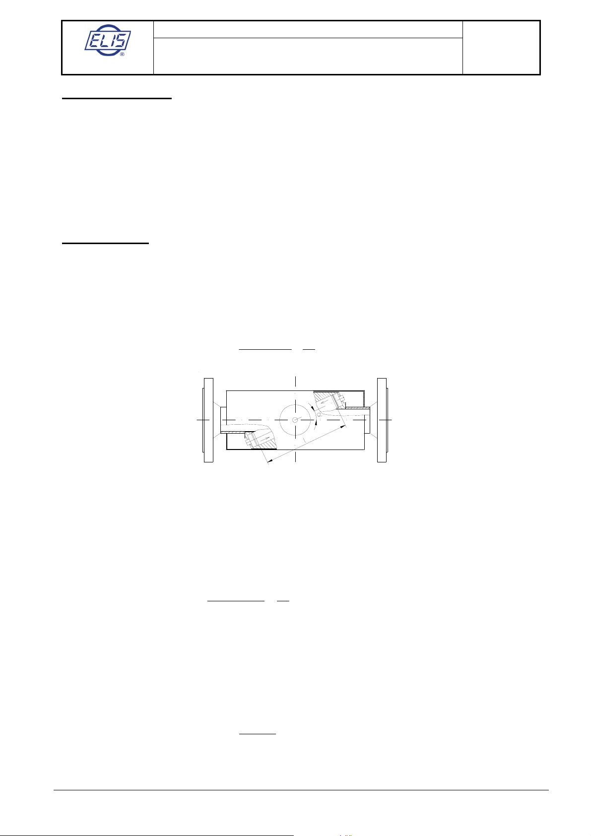
3.2. Flow meter design
3.2.1. The split version
3.2.1.1. Ultrasonic sensor including terminal box
On the outside, the two sensor models (UC 3.0 and UC 5.0) look the same. The principle difference consists in
the number and arrangement of the incorporated ultrasonic transducers. Sensor UC 3.0 includes two ultrasonic
transducers, sensor UC 5.0 four transducers.
The sensor body is a stainless-steel welded structure consisting of inner pipe with welded-on ultrasonic
transducer holders. The flanges (made of construction or stainless steel, according to the customer
requirements) are welded to the ends of the inner pipe. The transducers are provided with hermetic covers made
of construction or stainless steel. The electric terminal board is accommodated in an aluminium box with a
thermal insulation insert between it and the sensor body. The electrical connections are led through two (in the
case of a single-ray sensor) or four (double-ray sensor) PG 9 coaxial leadthroughs. A special valve prevents
water condensation inside the terminal box. The surface finish of the sensor assembly is a powder-paint coating,
hue RAL 7035 for the sensor body, and RAL 7016 for the terminal box. The sensor assembly dimensions are
shown in the following table:
Dimensional sketch of the sensor assembly:

ELIS PLZEŇa. s.
Design, Assembly and Service Manual
Page 7 of 44
Ultrasonic flow meter SONOELIS SE404X,
SONOELIS SE406X
ELIS PLZEŇa. s., Lucni 15, P. O. BOX 126, 304 26 Plzen, Czech Republic, Phone: +420/377517711, fax: +420/377517722 Es90201K/c
PN Nominal dim. DN 32 DN 40 DN 50 DN 65 DN 80
16/40 P mm140 150 165 185 200
16/40 S mm181 191 206 220 237
16/40 L mm360 360 360 360 360
PN Nominal dim. DN 100 DN 125 DN 150 DN 200 DN 250 DN 300
16 P mm220 250 285 340 405 460
16 S mm256 285 314 361 419 471
40 P mm235 270 300 375 450 515
40 S mm263 296 321 379 441 499
16/40 L mm360 360 360 450 450 450
Weight of the UC 3.0 ultrasonic sensors [kg]
DN PN 16 PN 40
32 9 9
40 9 9
50 11 11
65 12 12
80 15 15
100 17 17
125 18 20
150 19 21
200 28 37
250 45 70
300 58 84
Weight of the UC 5.0 ultrasonic sensors [kg]
DN PN 16 PN 40
32 12 12
40 16 16
50 ÷ 300 the same as UC 3.0

ELIS PLZEŇa. s.
Design, Assembly and Service Manual
Page 8 of 44
Ultrasonic flow meter SONOELIS SE404X,
SONOELIS SE406X
ELIS PLZEŇa. s., Lucni 15, P. O. BOX 126, 304 26 Plzen, Czech Republic, Phone: +420/377517711, fax: +420/377517722 Es90201K/c
3.2.1.2. Evaluation electronic unit
The evaluation electronic unit of the flow meter is located in a plastic box with a metal sheet base to be mounted
on a vertical support plate. At the front panel of the box there are the flow meter trade name and model/type
designation, product series number, the manufacturer’s trade name and logo, illuminated two-line display
(configurations STANDARD and COMFORT) and a control panel including four membrane push-buttons
(COMFORT only). A terminal strip is located at the bottom part of the box. To access the terminals it is
necessary to remove a plastic cover under seals. Fitted at the bottom wall of the box there are an earthing bolt
and at least five plastic leadthroughs (one PG 9 and four PG 7) for cables of circular cross-section. A
leadthrough size PG 9 will accommodate (and provide for air-tight assembly of) a cable of external diameter 6 to
8 mm, a PG 7 for a cable of external diameter 4 to 6 mm. Instead of one PG 7 leadthrough, a four-pole
connecter for the RS 485 line can be fitted.
Dimensional sketch of the electronic unit (the COMFORT configuration)
3.2.2. The compact version
In the compact version, the evaluation electronic unit is mounted directly onto the meter sensor (UC 3.0 or UC
5.0, see section 3.2.1.1 above) instead of the sensor terminal box. The electronic circuits are fitted into a cast
aluminium box coated with an RAL 1017 paint. As with the terminal box in the split version, a thermal insulating
insert is placed between the aluminium box and the sensor body. The mechanical connection is provided by four
bolts M5 with hexagon socket heads. With the bolts loosened the box can be rotated in horizontal plane by 340°.
At the rear part of the box there is a terminal strip under a cover held in position by six bolts M4 with hexagon
socket heads. The bottom wall of the box incorporates five leadthroughs (one PG 9 and four PG 7) for cables of
circular cross-section and a special valve preventing water condensation inside the box. The leadthroughs can
accommodate and provide for air-tight connection of cables of diameter 6 to 8 mm (PG 9) or 4 to 6 mm (PG 7).
The electronic unit is delivered with blinded bushings. At the front panel, there is the flow meter specification
information (meter name and model designation, as well as the manufacturer’s trade name). In the case of the
STANDARD configuration, there is also an illuminated two-line display; while the COMFORT model further
includes a display and a control push-button panel. Before starting-up check if all used bushings are tight
properly and all unused bushings blinded in appropriate way.

ELIS PLZEŇa. s.
Design, Assembly and Service Manual
Page 9 of 44
Ultrasonic flow meter SONOELIS SE404X,
SONOELIS SE406X
ELIS PLZEŇa. s., Lucni 15, P. O. BOX 126, 304 26 Plzen, Czech Republic, Phone: +420/377517711, fax: +420/377517722 Es90201K/c
Dimensional sketch of a compact version of the flow meter
PN Nominal dim. DN 32 DN 40 DN 50 DN 65 DN 80
16/40 P mm140 150 165 185 200
16/40 R mm268 278 293 307 324
16/40 L mm360 360 360 360 360
PN Nominal dim. DN 100 DN 125 DN 150 DN 200 DN 250 DN 300
16 P mm220 250 285 340 405 460
16 R mm343 372 401 448 506 558
40 P mm235 270 300 375 450 515
40 R mm350 383 408 466 528 586
16/40 L mm360 360 360 450 450 450
3.2.3. Commercial (invoicing) meters
Calibrated meters used for commercial purposes need be provided with officially certified seals to ensure that no
unauthorised modification of the meter functions or readings may take place. The official certification and meter
protection consist of:
- Stick-on labels with official seals of the responsible organisation to be attached on top of the meter type plate on
the evaluation electronic unit box;
- Two (or three, in the case of a compact version of the meter) official seals on the covers of the electronic unit
box to prevent any unauthorised meter setting action.
Further protective measures shall be adopted after the meter has been installed by a duly authorised technical
organisation:
- Two installation seals with official symbols imprinted thereon to prevent unauthorised opening of the cover of the
sensor terminal box (in the case of a split version of the meter);
- One (or two, in the case of a split version of the meter) installation seals with official symbols imprinted thereon
to prevent unauthorised opening of the terminal cover on the evaluation electronic unit box.
L

ELIS PLZEŇa. s.
Design, Assembly and Service Manual
Page 10 of 44
Ultrasonic flow meter SONOELIS SE404X,
SONOELIS SE406X
ELIS PLZEŇa. s., Lucni 15, P. O. BOX 126, 304 26 Plzen, Czech Republic, Phone: +420/377517711, fax: +420/377517722 Es90201K/c
4. SPECIFICATIONS
4.1. Ultrasonic sensors: nominal ID, rated and limit flow rates
For a given size of the flow meter sensor (UC 3.0 or UC 5.0), the maximum flow rate and other sensor
parameters can be found in the following table.
The data in the table relate to the measurement accuracy of flow rate q better than x% and the measurement
range of qmin x% q qs
Flow meter model SE404X
DN 32 40 50 65 80 100 125 150 200 250 300
qs m3/h20 32 50 80 150 240 350 500 900 1400 2000
q
p
m3/h10 16 25 40 75 120 175 250 450 700 1000
qmin 1% m3/h1.5 2.3 3.5 6 9 14 22 32 57 89 127
qmin 5% m3/h0.2 0.32 0.5 0.8 1.5 2.4 3.5 5.0 9.0 14 20
qNEC m3/h0.07 0.09 0.14 0.22 0.37 0.6 0.9 1.2 2.2 3.5 5
Flow meter model SE406X
DN 32 40 50 65 80 100 125 150 200 250 300
qs m3/h20 32 50 80 150 240 350 500 900 1400 2000
q
p
m3/h10 16 25 40 75 120 175 250 450 700 1000
qmin 0
,
5% m3/h1.5 2.3 3.5 6 9 14 22 32 57 89 127
qmin 3% m3/h0.2 0.32 0.5 0.8 1.5 2.4 3.5 5.0 9.0 14 20
qNEC m3/h0.07 0.09 0.14 0.22 0.37 0.6 0.9 1.2 2.2 3.5 5
where
qs is the overload (maximum) fluid flow rate,
qpis the steady-state (rated) fluid flow rate,
qmin is the minimum flow rate for specified measurement accuracy, and
qNEC is the sensitivity threshold (flow rate) level of the sensor concerned.
The minimum flow rate at which the flow meter starts to measure and deliver measured data is set by the
manufacturer at the value of qNEC. On customer’s request this threshold level can be reset within the range of
qNEC = 0 0,25qs. In the COMFORT meter configuration, the setting of the threshold level can be changed in
service using the appropriate procedure for the meter parameter adjustment.

ELIS PLZEŇa. s.
Design, Assembly and Service Manual
Page 11 of 44
Ultrasonic flow meter SONOELIS SE404X,
SONOELIS SE406X
ELIS PLZEŇa. s., Lucni 15, P. O. BOX 126, 304 26 Plzen, Czech Republic, Phone: +420/377517711, fax: +420/377517722 Es90201K/c
4.2. Flow meters: basic technical specifications
Rated pressure of the measured fluid (PN) 40 or 16
Temperature of the measured fluid 0 to +150 °C (split version)
0 to +90 °C (compact version)
Ambient temperature +5 to +55 °C
Maximum ambient relative humidity 80 %
Storage temperature -10 to +70 °C at the relative humidity up to 70 %
Protection class
- evaluation electronic unit, compact version
IP 67
- evaluation electronic unit, split version IP 65
- ultrasonic sensors UC 3.0, UC 5.0 IP 67
Sensor installed in piping Flanges 11, ČSN EN 1092-1
Connecting cables for sensors Standard length 5 m, maximum length 100 m
Max. difference in cable lengths 0.1 m
Electronic unit, split version
- dimensions
- weight
- power supply
- stand-by power supply
- power requirement
- mains fuse
- protection against electric shock,
ČSN 332000-4-41
length 230 mm, height 217 mm, width 85 mm
1.5 kg
100 250 V, 50/60 Hz
3 V, Li battery (Lifetime 5 years)
6 VA
T 250 mA, 250 V
automated disconnection from power supply in the TN-S network
Evaluation electronic unit, compact version
- dimensions
- weight
- power supply
- stand-by power supply
- power requirement
- mains fuse
- protection against electric shock, ČSN 332000-4-41
length 152 mm, height 135 mm, width 205 mm
2.5 kg
100 250 V , 50/60 Hz
3 V, Li battery (Lifetime 5 years)
6 VA
T 250 mA, 250 V
automated disconnection from power supply in the TN-S network
Fluid flow velocity minimum 0.1 m/s
maximum 10 m/s
Display (configurations STANDARD and COMFORT) 2 x 16-digit alphanumerical LC display
Outputs (optoelectronically isolated) impulse, 0.1 to 1,000 l/imp (impulse length 50 ms)
frequency, 0 to 1,000 Hz or 10 kHz
(corresponds to flow rate 0 to qs)
switching output 24 V AC/0,1 A
Optional equipment communication line RS 485
isolated current output 0 ÷20 mA or 4 ÷20 mA (corresponding to the flow
rate range of 0 to qs)
mass flow rate measurement accessory
modification for extended range of fluid temperature measurements; from -
20°C to +180°C (split version)
pipe-end flanges, flange packing pieces, bolts and nuts
sensor's protection IP 68
two direction flow measurement and direction indication
ELIS PLZEŇa. s.
Design, Assembly and Service Manual
Page 12 of 44
Ultrasonic flow meter SONOELIS SE404X,
SONOELIS SE406X
ELIS PLZEŇa. s., Lucni 15, P. O. BOX 126, 304 26 Plzen, Czech Republic, Phone: +420/377517711, fax: +420/377517722 Es90201K/c
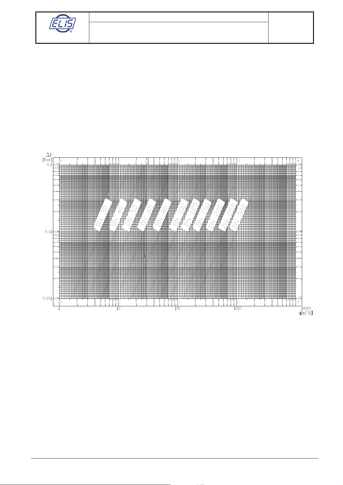
4.3. Sensor selection
The meter sensor shall be selected with respect to the fluid flow parameters at the measuring location. The
normal steady-state flow rate should be as close as possible to the qpvalue (the rated flow rate) of the sensor
(see the table in section 4.1 above). Attention shall be also paid to the pressure loss value of the sensor which,
although it is generally very low, adds up to the total losses of the fluid piping, in particular at high flow velocities.
In applications where the standard sensor parameters do not meet the operational requirements, the values of qs
and qmin of the selected sensor size can be re-set (in the COMFORT configuration using the customer control
push-button panel). The graph below shows the pressure loss values at various flow rates for particular sensor
sizes. It holds that the sensor parameter qmin is a fixed value in respect of the given measurement accuracy and
the sensor parameter qsshould not, for the given sensor size, exceed the maximum value given in the table in
section 4.1.
Pressure losses of ultrasonic sensors
4.4. Communication interface
All SONOELIS ultrasonic flow meters can be provided with isolated serial communication line RS 485. The
communication line parameters are: baud rate 4,800 Bd, 8-bit data format, one non-data bit, and optional parity
in both signal transmission directions. The communication protocol includes, among others, the measured and
processed fluid flow data such as instantaneous volume or mass flow rates, the total volume or mass of the fluid
flow, and the lengths of the periods of the meter operation, meter failure and power supply failure.
ELIS PLZEŇa. s.
Design, Assembly and Service Manual
Page 13 of 44
Ultrasonic flow meter SONOELIS SE404X,
SONOELIS SE406X
ELIS PLZEŇa. s., Lucni 15, P. O. BOX 126, 304 26 Plzen, Czech Republic, Phone: +420/377517711, fax: +420/377517722 Es90201K/c
5. METER INSTALLATION AND APPLICATION; BASIC RULES
When using an ultrasonic flow meter in a piping containing a particular fluid, certain conditions need be met to
ensure correct measurements. The limiting operational parameters of the fluid (i.e. temperature, pressure and
flow velocity) as well as the mechanical design and properties of the meter sensor (flow stabilisation piping
sections before and after sensor, complete flooding of the sensor cavity at all times, elimination of cavitation
effects and fluid foaming) must comply with the requirement for steady fluid flow with no gas bubbles or foam
appearing in the piping. Such conditions are different for various types of fluid and need be correctly identified for
each specific measuring spot and/or technological piping system.
CAUTION: Ultrasonic flow meter of a specific DN must not be used in piping of lesser sizes (smaller DN).
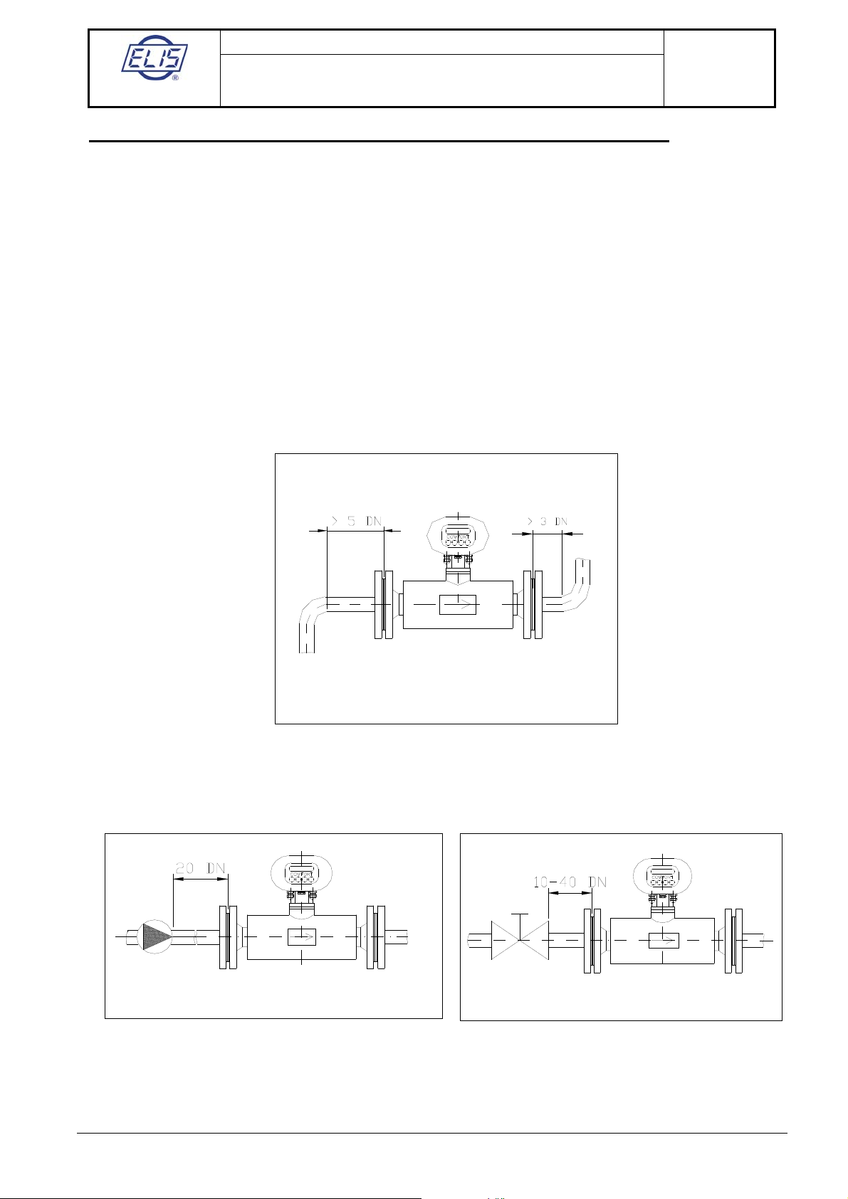
The ultrasonic flow meter shall be applied/installed in observance of certain rules concerning meter placement in
the fluid piping so as to ensure that the measurement accuracy complies with the meter specifications. Thus
sensor UC 3.0 requires flow-stabilisation straight sections of piping of the length of 5D (D = sensor ID) at the
input and 3D at the output where such arrangement effectively eliminates any flow disturbances due to 90° pipe
bends, changes in the piping diameter or similar simple flow-interference factors. With sensor UC 5.0, the same
flow stabilisation arrangement ensures a wider range of measured values at the specified measurement
accuracy (see section 4.1).
Required straight piping sections to stabilise the fluid flow through the sensor
If there is a pump located in the piping on the input side of the flow sensor, the required length of the stabilisation
piping is 20 D. If there is a valve or similar flow control element at the sensor input, the required stabilisation
length is 40 D. If such control element is fully open, the stabilisation length is 10 D.
Straight piping sections to stabilise the fluid flow after a “disturbance” in the piping
If any fluid-flow control element is located in the piping on the sensor output side, the sufficient length of the flow
stabilisation piping is 3 D.

ELIS PLZEŇa. s.
Design, Assembly and Service Manual
Page 14 of 44
Ultrasonic flow meter SONOELIS SE404X,
SONOELIS SE406X
ELIS PLZEŇa. s., Lucni 15, P. O. BOX 126, 304 26 Plzen, Czech Republic, Phone: +420/377517711, fax: +420/377517722 Es90201K/c
Required straight piping section for a “disturbance” located at the sensor output
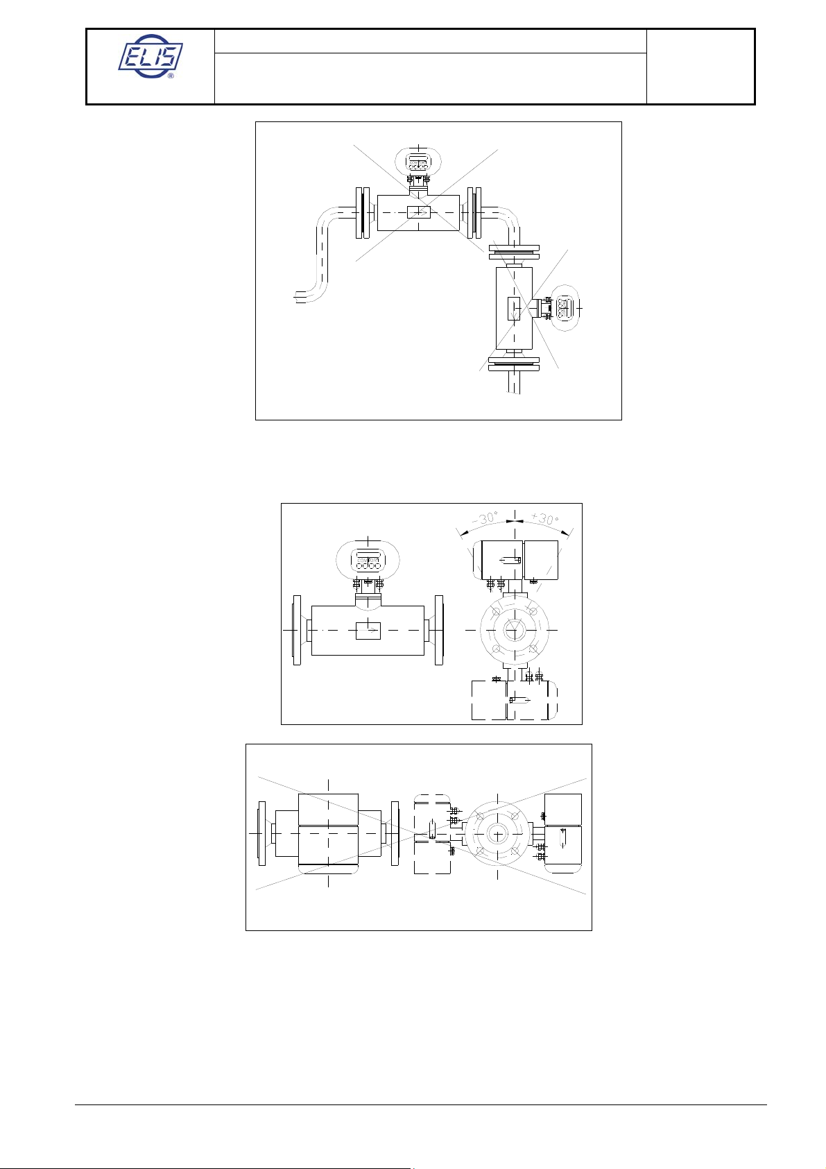
In the cases where, in the periods of low flow rate, the fluid level in various parts of the piping may sink, the flow
meter sensor shall be located at a bottom pocket of the piping to ensure full flooding of the sensor at all times.
Flow sensor location at the “bottom pocket” of the fluid piping
If a flow sensor is to be installed in a vertical section of the fluid piping, the fluid flow direction shall always be
upwards.
Sensor installed in a vertical section of the fluid piping
To ensure correct flow rate measurement, the internal section of the meter sensor shall always be filled with the
flowing fluid. Therefore the basic rule to follow regarding the meter sensor placement is to avoid top pockets in
the fluid piping and, in the cases where the sensor is located in a vertical section of the piping and/or near the
place where the fluid leaves the piping system, the flow direction in the sensor should not be downwards.
ELIS PLZEŇa. s.
Design, Assembly and Service Manual
Page 15 of 44
Ultrasonic flow meter SONOELIS SE404X,
SONOELIS SE406X
ELIS PLZEŇa. s., Lucni 15, P. O. BOX 126, 304 26 Plzen, Czech Republic, Phone: +420/377517711, fax: +420/377517722 Es90201K/c
Examples of incorrect sensor placement
The following pictures show correct and incorrect ways of the sensor installation in a horizontal piping section
with respect to the possible positioning of the meter display unit.
The measured fluid shall be free of larger solid particles and air bubbles either coming into the fluid through leaks
in the piping or originating by the cavitation process in the sensor or other piping components. If cavitation is
suspected to appear in the sensor or piping, the fluid pressure in the sensor or the respective piping section
needs be increased.
The above sensor installation rules apply to both compact version of the flow meter and the separately installed
sensor units provided with the terminal boxes (the “split” version of the meter).
In the piping systems used to deliver liquids such as rape-seed oil, black oil, caprolactan or chemical compounds
with easily separable components, it is recommended to mount flow meters in a vertical position with the

ELIS PLZEŇa. s.
Design, Assembly and Service Manual
Page 16 of 44
Ultrasonic flow meter SONOELIS SE404X,
SONOELIS SE406X
ELIS PLZEŇa. s., Lucni 15, P. O. BOX 126, 304 26 Plzen, Czech Republic, Phone: +420/377517711, fax: +420/377517722 Es90201K/c
measured fluid flowing upwards. This arrangement ensures better mixing action and homogenity of the fluid
flowing through the meter sensor.
The pressure loss vs. flow rate characteristics of individual sensor models are shown in a table in section 4.3
above. In the cases of commercial (invoicing) meters, the evaluation electronic unit of the meter shall be
supplied from the mains (230 V, 50 Hz) by a separate power line with an overcurrent circuit breaker to be sealed
at the ON position, where the switching-off actions shall be reserved to duly authorised staff only. The
recommended power supply cable is CYKY 3x1.5 mm2 with the external diameter 10.5 mm, and the associated
overcurrent circuit breaker should be rated at 6 A. The recommended cable for the RS 485 communication line
is JYTY – Al with laminated foil 2D x 1 mm2with a repeater for every 1,000 m of the line.
6. METER INSTALLATION GUIDE
The meter assembly and installation directions given in this manual shall be strictly observed.
To prevent undesirable interference between the power and signal devices, the power cables shall be placed at
least 25 cm away from all signal cables (the coaxial cables connecting the sensor with the signal processing
electronic circuits in the case of a split version of the meter, the RS 485 communication line and the output signal
cables). If a signal cable needs be extended, the cable conductors shall be soldered and the soldered joint
protected against environmental and mechanical stresses by a suitable installation box. All cables shall be led
outside the thermal insulation layers on the fluid piping. To connect a Pt 100 thermometer, the current output and
the RS 485 communication line, use shielded wires with the shield connected to the ground potential terminal on
terminal board X1 in the electronic unit box (or X2, see section 6.2 below). Shielded wires are also
recommended to be used for the frequency and impulse output signals where the shields should be connected
to the ground potential in the superordinated electronic control system.
Sensor must be grounded properly. For grounding use a conductor with minimum cross section area
4 mm2and connect the conductor to grounding bolts of evaluation electronic and flow sensor (see figure here
below).
Note:
During using of RS 485 communication is needed to follow these instructions:
1) Frequency of device calls is max. once per ten seconds
2) Call repeating by unsuccessful call is possible first in five seconds (in the case the device didn´t respond)
3) It can be requested only one service by call proceeding
Test device is running during the communication too. This test could be guided with short-term display blink.
It is not fault of device in any case.
Earthing connection between the sensor and the electronic unit (the split version)
zž4mm
2
M4
M4
COMFORT
a.s.ELIS PLZEÒ
SONOELIS
6.1. Electronic circuits (the split version)
The electronic signal processing unit shall be mounted in a vertical position on an installation frame. The
interconnection between the electronic unit and the meter sensors (UC 3.0 or UC 5.0) is described in section 6.2
below. The connecting coaxial cables should not differ in length by more than 0.1 m.
ELIS PLZEŇa. s.
Design, Assembly and Service Manual
Page 17 of 44
Ultrasonic flow meter SONOELIS SE404X,
SONOELIS SE406X
ELIS PLZEŇa. s., Lucni 15, P. O. BOX 126, 304 26 Plzen, Czech Republic, Phone: +420/377517711, fax: +420/377517722 Es90201K/c
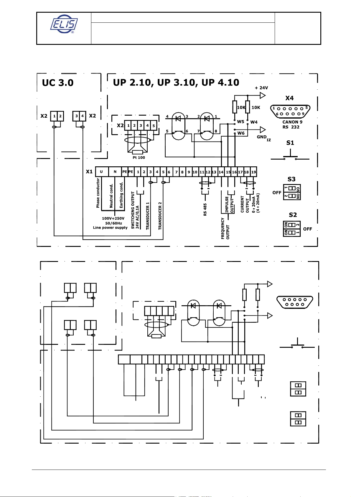
6.2. Electrical connections
A split version of flow meter with flow sensor UC 3.0
TRANSDUCER
1 2
RESET
A split version of flow meter with flow sensor UC 5.0
W6
24V AC/0,1A
RS 485
.
.
.
.
SWITCHING OUTPUT
TRANSDUCER 1
TRANSDUCER 2
TRANSDUCER 3
IMPULSE
OUTPUT
OUTPUT
CURRENT
TRANSDUCER 4
50/60Hz
Line power supply
100V÷250V
ON ON
2
FREQUENCY
OUTPUT
OFF
1
0
(4
S2
X2
1
X2 2 43
X1 PE
NU 1 3 42 5 6 7 8 109 1211 171514 1613 18 19PE
--
Earthing cond.
Neutral cond.
Phase conductor
++
S3
20mA
20mA)
1
OFF
ON ON
2
+
+-
+
Pt100
RESET
IZ
GND
S1
X2
4
3
TRANSDUCER
12
5
X2 87
6
UC 5.0
TRANSDUCER
2 1
X2 1 2 3 4 5
5 6 7
4 3 51
W4
W5
8
CANON 9
RS 232
9
6
10K 10K X4
UP 2.10, UP 3.10, UP 4.10 +24V
Note: Terminals X1 14 and 16 are used for uniform passive pulses.

ELIS PLZEŇa. s.
Design, Assembly and Service Manual
Page 18 of 44
Ultrasonic flow meter SONOELIS SE404X,
SONOELIS SE406X
ELIS PLZEŇa. s., Lucni 15, P. O. BOX 126, 304 26 Plzen, Czech Republic, Phone: +420/377517711, fax: +420/377517722 Es90201K/c
A compact version of flow meter
Connector X4 serves the purposes of the equipment calibration, servicing and parameter setting at the
manufacturer’s plant. The signal outputs (frequency, impulse and current outputs) are isolated and power from a
separate isolated power source. The frequency and impulse outputs can be used in either passive or active
operational modes, while the current output is always active. In view of the arrangement used (a common power
source and therefore the possibility of equalising currents flowing between the outputs), it is recommended not to
use more than two outputs in the active mode at any time. If the frequency and/or impulse outputs are used in
the passive mode (pins W1 through to W6 are disconnected), the optocoupler current shall not exceed 20 mA.
Pushbutton S1, if depressed, resets the data on the aggregate fluid volume that has passed through the flow
meter. Terminals 1 and 2 at terminal board X1 (in the case of a split version) or X2 (in the case of a compact
version of the meter) can be connected to a relay coil in series with an external AC power source and so provide
for indication of the flow direction or other selected parameter status. Thermometer Pt 100, if used, shall be
connected to terminals 1 to 5 at terminal board X2 (in the case of a split version) or X3 (in the case of a compact
version of the meter). The thermometer signal is used to convert the fluid volume data to mass data in special
flow meter configurations. If isolated voltage, frequency or impulse outputs are required, the W-pins shall be
connected as shown in the table below:
Type of el. unit UP 2.00, UP 3.00, UP 4.00 UP 2.10, UP 3.10, UP 4.10
Frequency output W3 to W1 W4 to W6
Impulse output W2 to W1 W5 to W6
As shown in the schematic diagrams in section 6.2 above, isolated current outputs 0 to 20 or 4 to 20 mA and an
output for the RS 485 communication line are available at specific terminals and can be used according to the
requirements of the customer. In the split version of the meter, the ultrasonic sensor is connected to the signal
processing unit by two or four coaxial cables (see the schematic diagrams).
If the flow meter is to serve the purposes of a standard/invoicing meter, switch S3 and one section of switch S2
should be sealed and provided with calibration mark. The remaining section of switch S2 (S2:1) may be used to
select display of the instantaneous velocity or flow rate of the measured fluid (applies to flow meters in the
STANDARD or COMFORT configurations).

ELIS PLZEŇa. s.
Design, Assembly and Service Manual
Page 19 of 44
Ultrasonic flow meter SONOELIS SE404X,
SONOELIS SE406X
ELIS PLZEŇa. s., Lucni 15, P. O. BOX 126, 304 26 Plzen, Czech Republic, Phone: +420/377517711, fax: +420/377517722 Es90201K/c
The following table shows the control functions of double switches S2 and S3.
Operational modes and combinations of the positions of switches S2 and S3
Measuring mode S2:1 position OFF
S2:2 position OFF
S3:2 position OFF
Configurations STANDARD and COMFORT: S2:1 position OFF – display shows the flow rate
S2:1 position ON – display shows the flow velocity
Service mode S2:2 position ON S3:2 position OFF
Programming mode S2:2 position OFF S3:2 position ON
6.3. Ultrasonic sensor
Ultrasonic sensors shall not be covered with thermal insulation. The connecting coaxial cables shall not be
attached to piping containing warm fluid. The sensors shall be installed in the piping in such a way as to ensure
that the associated electronic unit (in the case of a compact version) or the terminal box (in the split version of
the meter) is facing up or down.
The position of the sensor in the piping shall be such that the hydraulic part of the sensor is fully flooded by the
measured fluid at all times. If the sensor is installed in a vertical section of the piping, the measured fluid shall
only flow in the upward direction. Disregarding these or other sensor installation rules (see section 5) may result
in incorrect flow rate or flow volume readings.
6.4. Mechanical assembly and installation
Ultrasonic sensors shall be fitted into the piping by means of end flanges (size 11, ČSN EN 1092-1) with suitable
counterparts at the piping ends. The internal diameters of the pipe flanges and the piping itself shall be the same
as that of the sensor. The pipe flange faces shall be perpendicular to the piping axis. The piping sections
including sealing rings at the sensor input and output shall be co-axial with no protruding edges in the flow
channel.
The separate box with electronic circuits (in the case of a split version of the meter) shall be attached to a
suitable vertical support plate by means of four bolts of diameter 5 mm.
7. METER COMMISSIONING AND CONTROL
7.1. The ECONOMIC configuration
After the meter has been installed in the piping (which implies, in the case of a compact version, installation of
the complete meter or, in the case of a split version, installation of the flow sensor in the piping and connecting it
to a separate signal processing unit), the meter can be energised. Very soon (within a few seconds) the meter
will adopt the measuring (and data display) mode and the frequency, impulse and isolated current outputs will be
operative. The impulse and frequency outputs can be used either in the passive mode (where the function is
essentially that of a transistor switch with power supplied from the associated equipment) or in the active mode
where the output circuits are powered from an internal isolated source. The selection of the output mode of
operation is done by connecting or disconnecting the respective W pins (see section 6.2 above).
The aggregate flow volume or mass data transmitted by the RS 485 communication line can be reset either via
the communication line or manually, using the RESET push-button located under the terminal board cover.
7.2. The STANDARD configuration
Upon installation of the ultrasonic sensor in the piping and connecting it to the signal processing unit (the split
meter version), or installation in the piping of the compact version of the meter, the meter can be energised. After
a short initial period during which the system parameters are reset the meter starts measuring and the
frequency, impulse and current outputs become operative. Regarding the signal output mode and meter
resetting information refer to the previous section 7.1 (the ECONOMIC configuration).
Unlike the ECONOMIC, the STANDARD configuration includes a two-line alphanumeric display of 16 characters
per line. The first 15 characters on each line display the measured values, the last character shows the
operational status of the meter.

ELIS PLZEŇa. s.
Design, Assembly and Service Manual
Page 20 of 44
Ultrasonic flow meter SONOELIS SE404X,
SONOELIS SE406X
ELIS PLZEŇa. s., Lucni 15, P. O. BOX 126, 304 26 Plzen, Czech Republic, Phone: +420/377517711, fax: +420/377517722 Es90201K/c
7.2.1. Display data
The data on the display include selected measured quantities and information on the flow meter operational
status.
7.2.1.1. Meter status information
The first three seconds after connecting the meter to the power source the display reads
Flow meter
E L I S
In the normal operation, the symbol appearing at the last digit position on the second line informs about the
current mode of operation of the signal processing electronic unit. The characters used and their meanings are
as follows:
I electronic unit initialisation
+ measurements in the positive flow direction
- measurements in the negative flow direction
C calculation of measured values, output signal generation and display
W stand-by mode
T data communication (data being sent).
Under normal operating conditions the above characters regularly replace one another. In the case of an error
due to a sensor failure, loss of a sensor signal due to a cable failure, presence of an air bubble or a mechanical
particle in the fluid flow, an “R” will appear at the last position on the first line and the “I” and “+” signs will appear
in turns at the last position on the second line of the display unit. A failure of the electronic unit will usually be
manifested by discontinued regular changes of the system status symbols on the display.
7.2.1.2. Display of measured data
Up to three measured quantities can be displayed simultaneously; one on the first line, and the other two in turns
on the second line of the display unit. The switching frequency can be selected in terms of the number of
measuring cycles per display time of one measured quantity.
Most often the first display line is used to show the volume flow rate (in m3/hod) or the mass flow rate (in metric
tons per hour), and the second display line to display the total volume (in m3) or the total mass (in metric tons)
alternatively with the fluid temperature in °C. However, the customer is free to define other combinations of the
data to be displayed and/or to select other optional data units from the software menu available.
7.2.2. Review of the measured quantities
Volume flow rate
Relative volume flow rate (in % of qs)
Mass flow rate T
Relative mass flow rate (in % of qs) T
Volume (aggregate value)
Volume + (volume of the fluid passed in the positive direction) O
Volume - (volume of the fluid passed in the negative direction) O
Mass (aggregate mass) T
Mass + (mass of the fluid passed in the positive direction) T, O
Mass - (mass of the fluid passed in the negative direction) T, O
Temperature T
Density T
Sound propagation velocity
Fluid flow velocity through the sensor flange
Start of the measurement period (date and time of the last resetting command)
Duration of the measurement period
Duration of a meter error condition
Duration of a power failure period
Date
Time
Comment:
This manual suits for next models
1
Table of contents
Other Elis Measuring Instrument manuals


