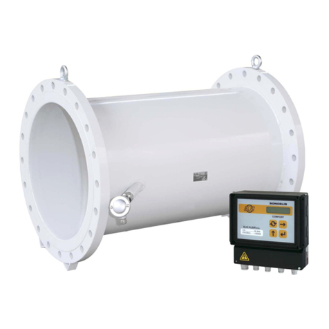
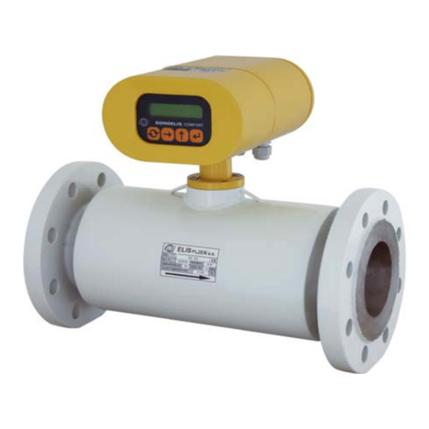
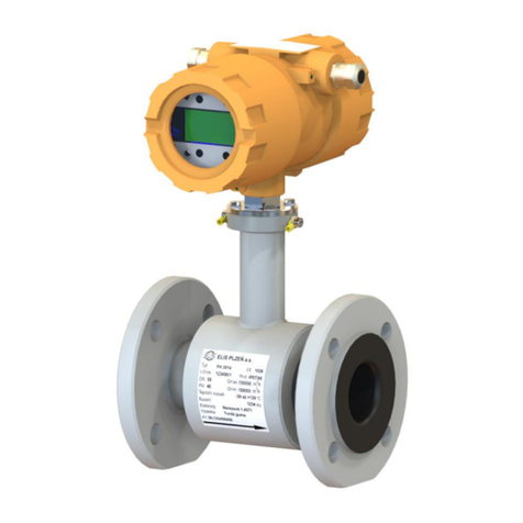
Elis FLONET FH30 Series User manual

Project design, installation and service manual
Page 1 of 72
Electromagnetic flowmeter FLONET FH30xx
ELIS PLZEa. s., 425/15, , Czech Republic, phone.: +420 377 517 711, fax: +420 377 517 722 Es 90678K
Electromagnetic flowmeter
FLONET FH30xx

Project design, installation and service manual
Page 2 of 72
Electromagnetic flowmeter FLONET FH30xx
ELIS PLZEa. s., 425/15, , Czech Republic, phone.: +420 377 517 711, fax: +420 377 517 722 Es 90678K
Content
1BASIC INFORMATION.......................................................................................................................5
1.1 Application.................................................................................................................................................5
1.3 Meter properties and functions ..................................................................................................................6
1.4 Important user information.........................................................................................................................6
1.4.1 Safety instructions................................................................................................................................6
1.4.2 Liability.................................................................................................................................................6
1.5 Product warranty........................................................................................................................................7
1.6 Representations and certificates................................................................................................................7
2METER IDENTIFICATION..................................................................................................................8
2.1 FLONET FH30xx flowmeter type designation............................................................................................8
2.2 Scope of delivery .......................................................................................................................................8
2.2.1 Compact meter version FLONET FH30x4............................................................................................8
2.2.2 Remote meter version FLONET FH30x5 .............................................................................................8
2.3 Associated documents...............................................................................................................................9
2.4 Flowmeter rating plates..............................................................................................................................9
2.4.1 Main meter plate ..................................................................................................................................9
2.4.2 Transmitter plate ..................................................................................................................................9
2.4.3 Sensor plate.......................................................................................................................................10
3METER DESIGN AND MATERIAL VERSIONS.............................................................................. 10
3.1 Compact and remote meter versions.......................................................................................................10
3.2 Operating pressure of the measured fluid................................................................................................12
3.3 Sensor dimensions ..................................................................................................................................14
3.4 Sensor lining............................................................................................................................................16
3.5 Electrode materials..................................................................................................................................16
3.6 Sensors for flowmeters FLONET FH30xx; review of sensor design and material versions .....................17
4INSTALLATION............................................................................................................................... 18
4.1 Taking over..............................................................................................................................................18
4.2 Meter handling.........................................................................................................................................18
4.3 Storage....................................................................................................................................................18
4.4 Installation conditions...............................................................................................................................19
4.4.1 General principles ..............................................................................................................................19
4.4.2 Straight piping sections......................................................................................................................19
4.4.3 Suppression of the pump effects........................................................................................................20
4.4.4 Suppression of the effects of closing valves.......................................................................................21
4.4.5 Suppression of vibration effects.........................................................................................................21
4.4.6 Piping stacks......................................................................................................................................22
4.4.7 Sensor flooding..................................................................................................................................22
4.4.8 Free discharge points.........................................................................................................................22
4.5 Tightening torque.....................................................................................................................................23
4.6 Thermal insulation....................................................................................................................................26
4.7 Flowmeter heating ...................................................................................................................................26

Project design, installation and service manual
Page 3 of 72
Electromagnetic flowmeter FLONET FH30xx
ELIS PLZEa. s., 425/15, , Czech Republic, phone.: +420 377 517 711, fax: +420 377 517 722 Es 90678K
5ELECTRICAL CONNECTIONS....................................................................................................... 26
5.1 Transmitter...............................................................................................................................................26
5.1.1 Terminal box ......................................................................................................................................26
5.1.2 Excitation circuit.................................................................................................................................27
5.1.3 Signal cables......................................................................................................................................27
5.2 Sensor connection box ............................................................................................................................29
5.3 Power and information cables..................................................................................................................29
5.4 Cable placement......................................................................................................................................30
5.5 Power supply specifications.....................................................................................................................30
5.6 Input and output connections...................................................................................................................30
5.6.1 Multifunction outputs OUT1, OUT2....................................................................................................30
5.6.2 Current output 4 to 20mA...................................................................................................................32
5.6.3 Communication interfaces..................................................................................................................34
5.6.3.1 Communication interface RS-485 MODBUS RTU.....................................................................34
5.7Grounding and potential equalising .......................................................................................................355
6METER COMMISSIONING.............................................................................................................. 37
6.1 Check on electrical connections ..............................................................................................................37
6.2 Check on meter housing tightness...........................................................................................................37
6.3 Check on the installed meter ...................................................................................................................37
6.4 Check on the meter operation conditions.................................................................................................38
7OPERATION.................................................................................................................................... 38
7.1 Meter energising......................................................................................................................................38
7.1.1 Display status.....................................................................................................................................38
7.2 Front panel and control buttons...............................................................................................................38
7.2.1 Display ...............................................................................................................................................38
7.2.2 Control button functions .....................................................................................................................38
7.3Flowmeter control ....................................................................................................................................39
7.3.1 Manual control....................................................................................................................................39
7.3.1.1 Basic screen..............................................................................................................................39
7.3.1.2 Control menu structure ...........................................................
7.3.1.3 Main menu.................................................................................................................................41
7.3.2 Remote meter control using the FLOSET 4.0 program......................................................................43
7.3.2.1 Communication interface MODBUS RTU..................................................................................43
8TECHNICAL DATA.......................................................................................................................... 44
9CALIBRATION................................................................................................................................. 47
9.1 General....................................................................................................................................................47
9.2 Reference conditions...............................................................................................................................47
9.3 Measurement accuracy............................................................................................................................47
9.3.1 Flowmeter FLONET FH30xx –standard measurement accuracy......................................................47
9.3.2 Flowmeter FLONET FH30xx –increased measurement accuracy ....................................................49
10 METER DESIGN DETAILS ............................................................................................................. 49
10.1 Transmitter...............................................................................................................................................49
10.2 Sensor .....................................................................................................................................................49

Project design, installation and service manual
Page 4 of 72
Electromagnetic flowmeter FLONET FH30xx
ELIS PLZEa. s., 425/15, , Czech Republic, phone.: +420 377 517 711, fax: +420 377 517 722 Es 90678K
10.3 Cable gland sizes.....................................................................................................................................50
10.4 Company seals........................................................................................................................................50
10.5 Dimensions and weight............................................................................................................................51
10.5.1 Sensor................................................................................................................................................51
10.5.1.1 Flanges according to EN 1092-1 ...............................................................................................51
10.5.1.2 Flanges according to ASME B16.5............................................................................................52
10.5.1.3 Wafer sensor .............................................................................................................................53
10.5.2 Transmitter.........................................................................................................................................54
10.5.2.1 Transmitter for compact meter version ......................................................................................54
10.5.2.2 Transmitter for remote meter version sensor protection class IP 67.......................................54
10.5.2.3 Transmitter for remote meter version sensor protection class IP 68.......................................55
10.5.3 Sensor connection box.......................................................................................................................55
11 FLOWMETER FAULTS................................................................................................................... 56
11.1 General rules ...........................................................................................................................................56
11.2 Spare PC boards and components..........................................................................................................56
11.3 Software and simulation devices..............................................................................................................56
11.4 Fault identification....................................................................................................................................57
11.5 Meter repair procedures...........................................................................................................................58
12 MAINTENANCE............................................................................................................................... 61
13 SERVICES ....................................................................................................................................... 61
14 WARRANTY .................................................................................................................................... 61
14.1 Warranty services....................................................................................................................................61
14.2 Post-warranty services.............................................................................................................................62
15 ORDER NUMBER............................................................................................................................ 63
16 ASSOCIATED DOCUMENTS AND STANDARDS......................................................................... 70
17 ANNEXES........................................................................................................................................ 71
17.1 Representation on meter decontamination..............................................................................................71

Project design, installation and service manual
Page 5 of 72
Electromagnetic flowmeter FLONET FH30xx
ELIS PLZEa. s., 425/15, , Czech Republic, phone.: +420 377 517 711, fax: +420 377 517 722 Es 90678K
1 BASIC INFORMATION
1.1 Application
FLONET FH30xx is an electromagnetic flowmeter intended for measurement of volume flow rate of
electrically conductive liquids in closed piping. The meter facilitates high-accuracy bi-directional flow
rate measurements at flow velocities ranging from 0.025 to 10 m/s. The minimum required conductivity
of the measured fluifor de-mineralised water it is 20 .
1.2. Measurement principle
The function of electromagnetic flowmeter is based on the Faraday induction law. The meter sensor
consists of a non-magnetic electrically non-conductive tube and two inbuilt electrodes that pick up the
induced voltage in a plane perpendicular to the direction of the magnetic power lines. The magnetic field
is generated by electric current flowing through two coils wound on the tube. The flow of the conductive
liquid through the tube gives rise to induced voltage Uproportional to the magnetic flux density B, flow
velocity vand the length of the virtual conductor l:
U = B × l × v
Uinduced voltage
Bflux density
ldistance between the measuring electrodes
vflow velocity of the measured liquid
For the given sensor size, the values of flux density and distance between electrodes are constant.
Therefore, the voltage induced on the electrodes is proportional to the velocity of the liquid flowing
through the sensor tube. The volume flow rate is then the product of the liquid flow velocity and the tube
cross-section: Q = v ×S.

Project design, installation and service manual
Page 6 of 72
Electromagnetic flowmeter FLONET FH30xx
ELIS PLZEa. s., 425/15, , Czech Republic, phone.: +420 377 517 711, fax: +420 377 517 722 Es 90678K
1.3 Meter properties and functions
The functions of the meter transmitter include visualisation of the measured values and, using the
associated control push-buttons, setting of the operational meter parameters.
Main flowmeter functions:
•Bi-directional measurements of:
ovolume flow rate;
oaggregate fluid volume passed through the meter sensor;
•Archiving of the measured data and information on specific operational events;
•Checking on sensor flooding condition.
Flowmeter interface facilities:
oTwo binary outputs, one current output
oCommunication interface RS-485 MODBUS RTU
1.4 Important user information
Electromagnetic flowmeters of the FLONET FH30xx type series are manufactured and tested in
accordance with the applicable international regulations and standards. To ensure successful meter
commissioning and meeting the specified metrological parameters, the user shall duly observe all
directions and recommendations given in the product manual.
1.4.1 Safety instructions
•Prior to any meter handling, the user and/or the meter installation staff shall get acquainted with the
meter documentation.
•When connecting the flowmeter to the power supply, due attention shall be paid to the applicable
national regulations and standards with special regard to the issues of labour safety and health
protection.
•The meter installation, electrical connection and commissioning work shall be performed by suitably
qualified operators.
•It is essential to observe all conditions and instructions given in the product manual regarding the
meter installation and electrical connection, and to pay due attention to all warning labels.
•Should the product show signs of incorrect function, the user shall not attempt to dismantle the
meter. Any repair work is reserved to the meter manufacturer or their duly authorised partners.
When sending a meter for repair, make sure to attach representation on decontamination as of
Chapter 17 (ANNEX) hereof (see page 71).
•The key meter parts are protected against dismantling by company seals. Should any such seal be
broken, the customer will forfeit their right to claim free warranty services.
1.4.2 Liability
ELIS flowmeters for liquids, delivers its products in the highest possible
a subject of copyrights. The same rights also apply to the documents delivered together with the product.
a.s. Any infringement of the aforementioned intellectual property is punishable.
The documents delivered with the product are meant for familiarizing with the product itself and with the
conditions of its use and installation. All flowmeter users are obliged to get familiar in detail with these

Project design, installation and service manual
Page 7 of 72
Electromagnetic flowmeter FLONET FH30xx
ELIS PLZEa. s., 425/15, , Czech Republic, phone.: +420 377 517 711, fax: +420 377 517 722 Es 90678K
instructions as described therein. Following the above mentioned
instructions will prevent the loss of warranty for reasons of incorrect installation and misapplication.
Installation of this flowmeter shall be performed only by a company trained for this purpose by ELIS
eiving the training, shall be fully responsible for the correct
caused by an incorrect installation, its wrong application or incompetent configuration or programming.
applicable standards. The accompanying documentation consists of Project design, installation and
service manual and Declaration of Conformity. The products have a warranty as stated in the
Confirmation of Purchase Order or in the Purchase Contract.
All product manuals are regularly updated and the current version is delivered together with the product
and also available on the Internet under www.elis.cz/en.
purchaser, s
General Terms and Conditions.
Deliveries of flowmeters shall be governed by the Czech Civil Code. The product is delivered pursuant
to the confirmed Purchase Order or P
differences in flowmeter parameters that were not confirmed in writing.
The following icons are used in the Project design, installation and service manual:
Warning: incorrect operation or erroneous flowmeter configuration may cause damage to
product or injury to persons.
Information about another flowmeter features or types of documents delivered together with
the product.
1.5 Product warranty
The flowmeter manufacturer provides product warranty in accordance with their valid commercial
conditions.
Additional information regarding warranty is included in Chapter 14 hereof.
1.6 Representations and certificates
Applicable to electromagnetic flowmeters of the FLONET FH30xx type series are representations and
certificates referred to in Chapter 17 below, namely:
•Representation on CE compliance

Project design, installation and service manual
Page 8 of 72
Electromagnetic flowmeter FLONET FH30xx
ELIS PLZEa. s., 425/15, , Czech Republic, phone.: +420 377 517 711, fax: +420 377 517 722 Es 90678K
2 METER IDENTIFICATION
2.1 FLONET FH30xx flowmeter type designation
Review of the flowmeter FLONET FH30xx design versions:
FLONET FH30xx
4Compact version COMFORT
5Remote version COMFORT
0 Non-standard sensor design
1Flanged flow-rate sensor
2Wafer flow-rate sensor
0Normal operating environment
3 Transmitter C14.00 (95 to 250VAC) / C15.00 (24V 20%)
2.2 Scope of delivery
2.2.1 Compact meter version FLONET FH30x4
•Flowmeter FLONET FH30x4 with interfaces RS-485 MODBUS RTU
•Product manual Electromagnetic flowmeter FLONET FH30xx
•Product manual Electromagnetic flowmeters of the type series FLONEX FXx11x and FLONET
FH30xx Meter control instructions
•Product manual Communication interface RS-485 MODBUS RTU
Electromagnetic flowmeters FLONET FH30xx and FLONEX FXx11x
2.2.2 Remote meter version FLONET FH30x5
•Transmitter for FLONET FH30x5 including signal cable / connector, communication interface
RS-485 MODBUS RTU and communication interface HART
•Meter sensor and connection box
•Product manual Electromagnetic flowmeter FLONET FH30xx
•Product manual Electromagnetic flowmeters of the type series FLONEX FXx11x and FLONET
FH30xx Meter control instructions
•Product manual Communication interface RS-485 MODBUS RTU
Electromagnetic flowmeters FLONET FH30xx and FLONEX FXx11x
•Transmitter holder

Project design, installation and service manual
Page 9 of 72
Electromagnetic flowmeter FLONET FH30xx
ELIS PLZEa. s., 425/15, , Czech Republic, phone.: +420 377 517 711, fax: +420 377 517 722 Es 90678K
2.3 Associated documents
•Representation on CE compliance
•Calibration report optional (provided on request)
2.4 Flowmeter rating plates
2.4.1 Main meter plate
The main meter rating plate is located on top of the meter housing.
Both compact and remote meter versions
Example of the main meter plate
Comments
1 Manufacturer’s name and address
2 CE mark and identification numbers of relevant authorities
2.4.2 Transmitter plate
The transmitter rating plate is attached to the rear cover of the transmitter terminal box.
Both compact and remote meter versions
Example of the transmitter plate
Comments
1 Transmitter for both compact and remote meter versions
2 Power supply 95 to 250VAC, 45 to 65Hz, 3VA max., or 24 ± 20% VDC, 3W max.
3 Output functions (binary, frequency, pulse or current outputs, communication interface) are pre-set in production as
required in the product order documentation, but the user may subsequently change the setting.
2
2
3
1
1

Project design, installation and service manual
Page 10 of 72
Electromagnetic flowmeter FLONET FH30xx
ELIS PLZEa. s., 425/15, , Czech Republic, phone.: +420 377 517 711, fax: +420 377 517 722 Es 90678K
The initial output parameter setting is described in the flowmeter delivery note.
2.4.3 Sensor plate
The sensor rating plate is attached to the induction sensor housing.
Both compact and remote meter versions
Example of the sensor plate
Comments
1 Sensor pressure parameters in reference to the PED directive
2 Ambient temperature
3Temperature of the measured fluid
3 METER DESIGN AND MATERIAL VERSIONS
3.1 Compact and remote meter versions
In the cases of compact flowmeter version, the meter sensor and transmitter are connected internally
and are integrated into a single unit.
In the remote meter version, the sensor and transmitter are connected by a cable.
The remote flowmeter version is preferable in the following cases:
•the measured fluid temperatures in excess of 70C;
•space limitations not permitting application of the compact meter version;
2
1
3

Project design, installation and service manual
Page 11 of 72
Electromagnetic flowmeter FLONET FH30xx
ELIS PLZEa. s., 425/15, , Czech Republic, phone.: +420 377 517 711, fax: +420 377 517 722 Es 90678K
•where the meter installation spot is difficult to reach.
To eliminate the risk of electromagnetic interference acting on the connecting cable, the transmitter
should be as close as possible to the meter sensor.
Remote meter version including a sensor of protection class IP67
The meter sensor is supplied including a signal cable of the length specified by the customer. During
the on-site meter installation, the cable shall be brought to the transmitter connection box and connected
to the transmitter terminals.
Remote meter version IP 67 sensor
Remote meter version including a sensor of protection class IP68
The signal cable end to be connected to the meter transmitter is provided with a connector. The
matching connector is on the transmitter housing. The other cable end is brought to the sensor
connection box where it is permanently connected to the electrical circuits of the sensor and the box is
subsequently filled with hermetic insulating compound.
Remote meter version IP 68 sensor
Meter installation in the fluid piping:
•Flanged meter version
•Wafer meter version (sensor to be fitted between two flanges)

Project design, installation and service manual
Page 12 of 72
Electromagnetic flowmeter FLONET FH30xx
ELIS PLZEa. s., 425/15, , Czech Republic, phone.: +420 377 517 711, fax: +420 377 517 722 Es 90678K
Compact Wafer meter version Compact flanged meter version
3.2 Operating pressure of the measured fluid
As electromagnetic flowmeters have been designed for the maximum permitted operating pressure
PS in excess of 0.5 bar, they are, in reference to the Directive of the European Parliament and
Council No 97/23/ES considered pressure equipment and as such assigned to pressure equipment
categories 0 (SEP*), I, II or III.
Comment: * Sound Established Procedure
To select the correct rated pressure of the sensor flanges, the following parameters should be
considered:
•Maximum operating pressure of the measured fluid, PS;
•Rated inner diameter (DN) of the connected piping;
•Maximum temperature of the measured fluid, TS.
Standard sensor design
Operating pressure of flanged sensors according to standard EN 1092-1; material: carbon steel
Rated sensor size
DN
Rated
sensor
pressure
PN
Maximum permitted pressure PS (bar)
for maximum permitted temperature TSmax*
TSmax = 80°C
(sensor lining
materials
HR, SR, SPR)
TSmax = 110°C
(lining PTFE,
E-CTFE)**
TSmax = 120°C
(lining
E-CTFE)**
TSmax = 150°C
(lining PTFE)**
DN15 to DN50
PN40
38.3
36.7
-
35.2
DN65 to DN200
PN16
15.3
14.6
-
14
DN250 to DN700
PN10
9.5
9.1
9.0
8.8
DN800 to DN1200
PN6
5.5
5.4
-
5.2
Comments: * applicable to flanges made of materials of class 3E0 according to EN1092-1, such as steel
P245GH or P265GH
** available on special request for sensor sizes in excess of DN300

Project design, installation and service manual
Page 13 of 72
Electromagnetic flowmeter FLONET FH30xx
ELIS PLZEa. s., 425/15, , Czech Republic, phone.: +420 377 517 711, fax: +420 377 517 722 Es 90678K
Operating pressure of flanged sensors according to standard ASME B16.5; material: carbon steel
Rated sensor
size
DN
Rated
sensor
pressure
PN
Maximum permitted pressure PS (bar)
for maximum permitted temperature TSmax*
TSmax = 80°C
(lining
HR, SR, SPR)
TSmax = 110°C
(lining PTFE,
E-CTFE)**
TSmax = 120°C
(lining
E-CTFE)**
TSmax = 150°C
(lining PTFE)**
NPS ½“ to 24“
Class 150
15.9
15.9
15.9
15.8
Comments: * flanges made of materials of class 3E0 according to EN1092-1, such as steel P245GH or
P265GH
** available on request for sensor sizes in excess of NPS 12“
Operating pressure of Wafer sensors; material: carbon steel
Rated sensor
size
DN
Rated
sensor
pressure
PN
Maximum permitted pressure PS (bar)
for maximum permitted temperature TSmax*
TSmax = 80°C
(lining
HR, SR, SPR)
TSmax = 110°C
(lining PTFE)
TSmax = 150°C
(lining PTFE)**
DN20 to DN50
PN40
38.3
36.7
35.2
DN65 to DN200
PN16
15.3
14.6
14
Comments: * flanges made of material class 3E0 according to EN1092-1, such as steel P245GH or
P265GH
** available on request only
The values of PS (maximum permitted pressure) and TS (maximum permitted temperature), related to
a specific sensor, are shown on the flowmeter sensor plate. Specified on the sensor plate also is the
PED category.
Upon consultation with the manufacturer and in consideration of the pressure and temperature
characteristics of other flange materials as specified in standards EN 1092-1 and ASME B16.5, meter
sensors can be provided with flanges of other PS and TS parameters.
Pressure vs. temperature classes of flanges according to standard EN 1092-1
Maximum permitted temperature TS (C)
Maximum permitted pressure PS (bar)

Project design, installation and service manual
Page 14 of 72
Electromagnetic flowmeter FLONET FH30xx
ELIS PLZEa. s., 425/15, , Czech Republic, phone.: +420 377 517 711, fax: +420 377 517 722 Es 90678K
Pressure vs. temperature classes of flanges according to standard ASME B16.5
Maximum permitted temperature TS (C)
3.3 Sensor dimensions
Electromagnetic flowmeters FH30xx are intended for flow rate measurements with the fluid flow velocity
within the range of 0.025 to 10 m/s. In practical situations it is recommended to limit the fluid flow velocity
values to the range of 0.5 to 5 m/s. At low fluid flow velocities, the relative measurement error tends to
increase, while at high velocities flow turbulences may occur.
If the inner sensor diameter is the same as those of the connecting piping, the pressure loss at the meter
sensor is negligible.
If the operating fluid flow velocity is too low and the measurement error too high it is possible to
increase the fluid velocity by using a meter sensor of a smaller size with the corresponding
reduction of the inner diameters of the connecting pining. The disadvantage of this solution
consists of a pressure loss at the pipe reduction area. Therefore, in practical situations, to
reduce the pressure loss to a reasonable value, the pipe size reduction should be limited to a
single degree.
Fluid flow velocity in a piping can be calculated using the formula:
v
=
0.0003536 × Q
(m/s, m3/h, m)
DN 2
Maximum permitted pressure PS (bar)

Project design, installation and service manual
Page 15 of 72
Electromagnetic flowmeter FLONET FH30xx
ELIS PLZEa. s., 425/15, , Czech Republic, phone.: +420 377 517 711, fax: +420 377 517 722 Es 90678K
Flow rates for various sensor dimensions
DN
NPS
l/s
m3/h
Q1
v = 0.025 m/s
Q4
v = 10 m/s
Q1
v = 0.025 m/s
Q4
v = 10 m/s
15
0.0036
1.80
0.013
6,5
20
0.0067
3.33
0.024
12
25
0.0100
5
0.036
18
32
0.0167
8.33
0.060
30
40
0.0250
12.50
0.090
45
50
0.0400
20
0.144
72
65
0.0667
33.33
0.240
120
80
0.1000
50
0.360
180
100
0.1556
77.77
0.560
280
125
5
0.2389
119.44
0.860
430
150
0.3611
180.55
1.300
650
200
0.6389
319.44
2.300
1 150
250
1.0000
500
3.600
1 800
300
1.4000
700
5.040
2 520
350
1.9444
972
7.000
3 500
400
2.5000
1250
9.000
4 500
500
4.0000
2 000
14.400
7 200
600
5.5556
2 778
20.000
10 000
700
7.7778
3 889
28.000
14 000
800
10.0000
5 000
36.000
18 000
900
12.7778
6 389
46.000
23 000
1000
15.5556
7 778
56.000
28 000
1200
22.2222
11 111
80.000
40 000
Relationship between fluid flow velocity and flow rate for various sensor sizes
Flow rate Q (l/s)
Flow velocity (/s)

Project design, installation and service manual
Page 16 of 72
Electromagnetic flowmeter FLONET FH30xx
ELIS PLZEa. s., 425/15, , Czech Republic, phone.: +420 377 517 711, fax: +420 377 517 722 Es 90678K
3.4 Sensor lining
The sensor lining material shall be chosen with respect to the type and properties of the measured fluid.
In cases of the meter application in chemical or food-processing industries, the user should consult the
choice of the best suitable lining with the meter manufacturer.
The sensors used with flowmeters FLONET FH30xx can be supplied lined with one of the following
materials:
•Soft rubber
•Hard rubber
•Hard rubber for drinking water
•PTFE
•E-CTFE
General properties
Soft rubber (SR)
Soft rubber is a material with high resistance to abrasion. It is recommended for less chemically
aggressive operating environments (fluids) containing abrasive particles. This material is also noted for
good resistance to dilatations and rapid temperature
Hard rubber (HR)
Material is suitable for medium-aggressive liquids with operating temperatures in the range of 0
to + (hot service water, condensate and similar fluids).
Hard rubber for drinking water (SPR)
Lining material is suitable for most applications in water management and water supply systems. Here
hard rubber shall be certified for safe contact with drinking water. It is also recommended for medium-
aggressive liquids with operating temperatures from 80
PTFE
PTFE lining is suitable for applications in chemical and food-processing industries. It can also be used
with aggressive liquids at operating temperatures ranging from
PTFE lining can also be used in applications with the occurrence of underpressure 0 to 0,5
nt is required.
E-CTFE
Chemical resistance of this type of lining is similar to that of PTFE. E-CTFE lining is suitable for
applications in chemical industry where the temperatures of the operational fluid range from
3.5 Electrode materials
Standard materials for the measuring and grounding electrodes:
•Stainless steel 1.4571 (in combination with lining materials SR, HR or SPR)
•Hastelloy C276 (in combination with lining materials PTFE or E-CTFE)
Optional materials:
•Hastelloy C276
•Titanium
•Tantalum
•Platinum and Rhodium

Project design, installation and service manual
Page 17 of 72
Electromagnetic flowmeter FLONET FH30xx
ELIS PLZEa. s., 425/15, , Czech Republic, phone.: +420 377 517 711, fax: +420 377 517 722 Es 90678K
3.6 Sensors for flowmeters FLONET FH30xx; review of sensor
design and material versions
Overview of structural and material variants
FLONET FH30xx sensors:
Marked cells indicate production program

Project design, installation and service manual
Page 18 of 72
Electromagnetic flowmeter FLONET FH30xx
ELIS PLZEa. s., 425/15, , Czech Republic, phone.: +420 377 517 711, fax: +420 377 517 722 Es 90678K
4 INSTALLATION
4.1 Taking over
When taking over a delivered product, visual inspection shall be carried out to confirm the integrity of
both the product and its packaging.
The correct scope of delivery shall be checked in reference to the product order, delivery note and
product rating plates.
4.2 Meter handling
Avoid lifting the meter by holding onto any transmitter part or connection box; use for this purpose the
meter flanges or lifting eyes only.
In transport, to avoid irreversible damage to the meter lining, do not place any auxiliary
component parts into the meter piping.
Forbidden gripping Recommended gripping
When using lifting equipment, apply suitable textile slings; application of metal chains or cables might
result in damage to the meter.
It is recommended to transport the meter to the installation site in transport packaging.
4.3 Storage
For a flowmeter in storage, it is essential to:
•Observe the specified storage conditions regarding temperature and humidity;
•Avoid long-term meter exposure to direct sunshine (risk of damage to the meter display).
It is recommended to store the meter in complete transport packaging and remove the
covers and packaging materials only immediately before installation.

Project design, installation and service manual
Page 19 of 72
Electromagnetic flowmeter FLONET FH30xx
ELIS PLZEa. s., 425/15, , Czech Republic, phone.: +420 377 517 711, fax: +420 377 517 722 Es 90678K
4.4 Installation conditions
4.4.1 General principles
Applicable to mechanical installation of the flowmeter are the following rules:
•The protection covers and packaging shall only be removed immediately before the meter installation;
•The arrow on the sensor housing shall point at the positive fluid flow direction;
•In cases of sensor installation into vertical piping the fluid flow direction shall be upwards;
•The piping flanges shall be parallel to one another;
•The inner piping and seal diameters shall correspond to the inner sensor diameter;
•The seals and grounding rings shall be correctly fitted between the flanges and not extend in the
flow profile;
•The piping supports before and after the flowmeter location shall minimise the mechanical stresses
acting on the sensor (vibration, tension, bend and others);
•No piping support shall be located under the meter sensor;
•The transmitter shall be protected from direct sunshine;
•The meter installation location shall be selected so as to ensure easy access for the operator to the
transmitter and all meter rating plates;
•The meter sensor shall always be fully flooded by the measured fluid to avoid aeration;
•In cases of electrically non-conductive piping the measured fluid shall be grounded by means of
grounding rings.
The sensor shall be inserted between the piping flanges by a shifting movement. With larger
sensor sizes it is recommended to use installation inserts. It is also advisable, during the sensor
insertion in the piping, to protect the sealing surfaces on the lining by a metal sheet or similar
material.
Following the meter installation, no subsequent electric-arc welding operations shall be
carried out on the piping at the sensor location. In particular, avoid welding on the piping
flanges connected to the meter sensor.
4.4.2 Straight piping sections
To ensure correct functioning of an electromagnetic flowmeter, conditions shall be provided for
continuous fluid flow and flow profile stability in the meter sensor.
Before and after the meter sensor there shall be straight piping sections the required lengths of which
are specified as multiples of the inner piping diameter. In cases of bi-directional measurements, the
same requirements concern straight piping sections before and after the sensor. If there are flow-
disturbing elements (such as bend or fitting) in the piping near the sensor location, the required length
of straight piping section shall be increased multiplied by the number of such elements.
At the contact plane between the sensor and the attached piping there shall not be any protruding edges
causing the flow turbulence. The inner diameter of the piping shall not be smaller or greater by more
than 3% than that of the sensor.
Avoid sensor placement at locations where at the sensor input are chemicals (especially chloride
compounds) injected or dosed in the measured fluid. Imperfect blending of the fluid components may
cause errors in the flow rate measurements or, in extreme cases, reduction of the measured flow rate
to nil.
Preferable are flowmeter sensor installation locations before any piping elements affecting the smooth
flow of the measured fluid.
In cases of bi-directional flow measurement, the basic required length of straight piping sections in front
of and behind the flowmeter is 5DN.

Project design, installation and service manual
Page 20 of 72
Electromagnetic flowmeter FLONET FH30xx
ELIS PLZEa. s., 425/15, , Czech Republic, phone.: +420 377 517 711, fax: +420 377 517 722 Es 90678K
Installation of a flowmeter of a smaller size than that the attached piping requires the use of cone-shaped
In cases of sensor installation in horizontal piping, to prevent generation of air bubbles in the fluid, it is
recommended to use eccentric reduction pieces (see standard EN 6817).
straight piping length.
4.4.3 Suppression of the pump effects
To prevent creation of a low-pressure zone in the sensor and possible damage to the sensor lining, a
pump shall always be placed before (at the input side of) the sensor. The length of the straight piping
section between the pump and the sensor shall be at least 25 DN.
Placing the pump before the meter sensor reduces the cavitation effect and release of gases
from the measured fluid. Increased pressure in the piping system will keep the fluid above the
saturated vapour pressure and prevent cavitation effects.
Table of contents
Other Elis Measuring Instrument manuals
