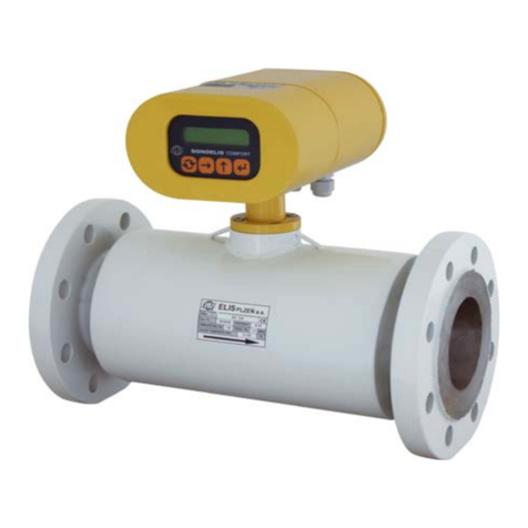
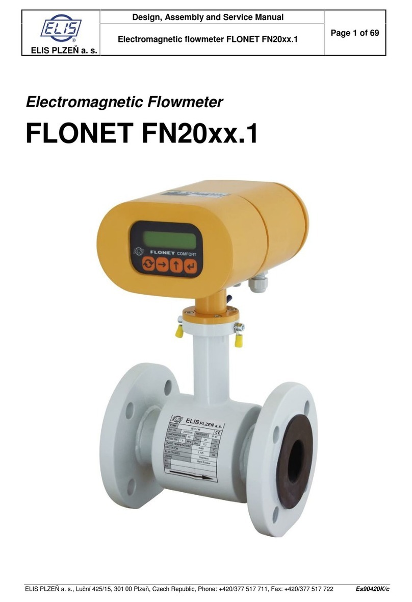
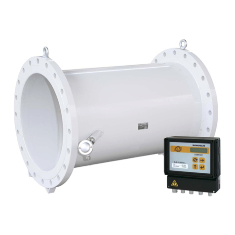
Elis FLONET FN50 Series User manual

ELIS PLZEŇ a. s.
Design, Assembly and Service Manual
Page 1 of 32
Electromagnetic flowmeter FLONET FN50xx.1
ELIS PLZEN a. s., Lucni 425/15, 301 00 Plzen, Czech Republic, Phone: +420/377 517 711, fax: +420/377 517 722 Es90716K
Electromagnetic Flowmeter
FLONET FN50xx.1

ELIS PLZEŇ a. s.
Design, Assembly and Service Manual
Page 2 of 32
Electromagnetic flowmeter FLONET FN50xx.1
ELIS PLZEN a. s., Lucni 425/15, 301 00 Plzen, Czech Republic, Phone: +420/377 517 711, fax: +420/377 517 722 Es90716K

ELIS PLZEŇ a. s.
Design, Assembly and Service Manual
Page 3 of 32
Electromagnetic flowmeter FLONET FN50xx.1
ELIS PLZEN a. s., Lucni 425/15, 301 00 Plzen, Czech Republic, Phone: +420/377 517 711, fax: +420/377 517 722 Es90716K
Content
1. APPLICATION ...............................................................................................................................................4
2. MEASUREMENT PRINCIPLE ......................................................................................................................4
3. TECHNICAL DESCRIPTION.........................................................................................................................5
3.1. GENERAL................................................................................................................................................................... 5
3.2. METER DESIGN........................................................................................................................................................... 5
3.3. PROTECTION OF METERS AGAINST UNPROFESSIONAL HANDLING..................................................................................... 7
4. TECHNICAL PARAMETERS.........................................................................................................................8
4.1. FLOW SENSOR............................................................................................................................................................ 8
4.1.1. Selection of correct sensor size........................................................................................................................ 8
4.1.2. Operational pressure of measured liquid........................................................................................................ 12
4.1.3. Material of electrodes..................................................................................................................................... 12
4.1.4. Selection of sensor lining ............................................................................................................................... 12
4.1.5. Dimensions of flangeless sensor ISX.Mxx (for heat meters).......................................................................... 13
4.1.6. Dimensions of flanged sensor IS0.Mxx (for heat meters)............................................................................... 14
4.1.7. Dimensions of flangeless sensor ISX.1xx ..................................................................................................... 15
4.1.8. Dimensions of flanged sensor ISX.1xx........................................................................................................... 16
4.1.9. Technical data of sensor................................................................................................................................ 17
4.2. ELECTRONIC UNIT BOX .............................................................................................................................................. 18
4.2.1. Electronic unit specifications.......................................................................................................................... 18
5. METER APPLICATION RULES ............................................................................................................... 19
5.1. SENSOR PLACEMENT IN PIPING................................................................................................................................... 19
5.2.SENSOR EARTHING ................................................................................................................................................... 21
6. FLOWMETER INSTALLATION AND OPERATIONAL START................................................................. 22
6.1. SENSOR INSTALLATION.............................................................................................................................................. 22
6.2. ELECTRIC CONNECTIONS OF ELECTROMAGNETIC FLOWMETER ....................................................................................... 22
6.2.1. Connection to power source........................................................................................................................... 22
6.2.2. Output signal connections.............................................................................................................................. 23
6.3. OPERATIONAL START ................................................................................................................................................ 24
7. OPTIONAL SETTINGS............................................................................................................................... 24
7.1. Samples............................................................................................................................................................ 24
7.2. Pulse output OUT1............................................................................................................................................ 25
8. ERROR REMOVAL AND METER REPAIR PROCEDURES FN50X0....................................................... 25
8.1. FLOW-METERREPAIR PROCEDURE................................................................................................................. 26
9. PACKAGING............................................................................................................................................... 27
10. PRODUCT ACCEPTANCE....................................................................................................................... 27
11. WARRANTY CONDITIONS...................................................................................................................... 27
12. PRODUCT ORDERING ............................................................................................................................ 28

ELIS PLZEŇ a. s.
Design, Assembly and Service Manual
Page 4 of 32
Electromagnetic flowmeter FLONET FN50xx.1
ELIS PLZEN a. s., Lucni 425/15, 301 00 Plzen, Czech Republic, Phone: +420/377 517 711, fax: +420/377 517 722 Es90716K
1. APPLICATION
The FLONET FN50xx.1 electromagnetic flowmeter has been designed to measure volume flow rates of
electrically conductive liquids in closed piping systems. It enables flow measurement with high accuracy in a
wide range of flow rates (0.05 to 10 m/s) unlike the previous type FLONET FN20xx.1 (range 1:100) in
extended range 1:200.
It is supplied in a compact design (dismountable piece of flow sensor and electronic unit) as a “blind”
(without a display) low-cost flowmeter for heat and cold measurement systems.
There is also a remote design of this flowmeter with a junction box on the top of chimney connected
to a cable with an electronic unit fitted with L-shaped steel angle bracket at the other end of the cable.
Power supply range is 230 VAC (or110 VAC). The flowmeter has only one galvanic isolated passive pulse
output OUT1.
The basic parameters can be set during activation process using special USB channel and sw FLOSET (it
isn’t standard in a delivery) .
2. MEASUREMENT PRINCIPLE
The function of an electromagnetic flowmeter is based on Faraday’s induction law. The meter sensor
consists of a non-magnetic and non-conductive tube with two embedded measuring electrodes to pick up the
induced voltage. To create an alternating magnetic field, two coils are fitted onto the tube in parallel with the
plane defined by the active parts of the measuring electrodes. Now if a conductive liquid flows across
magnetic field B, voltage Uwill appear on the measuring electrodes proportional to the flow velocity v and
the conductor length l.
U = B x l x v
Uinduced voltage
B magnetic flux density
l distance between the measuring electrodes
v liquid flow velocity
As the magnetic flux density and distance between the electrodes are constant, the induced voltage is
proportional to the liquid flow velocity in the tube. The value of the volume flow rate can then be readily
determined as a product of the flow velocity and square section of the tube, Q = v x S.

ELIS PLZEŇ a. s.
Design, Assembly and Service Manual
Page 5 of 32
Electromagnetic flowmeter FLONET FN50xx.1
ELIS PLZEN a. s., Lucni 425/15, 301 00 Plzen, Czech Republic, Phone: +420/377 517 711, fax: +420/377 517 722 Es90716K
3. TECHNICAL DESCRIPTION
3.1. General
The electromagnetic flowmeter consists of a sensor through which the measured liquid flows and an
electronic unit where the low-level signal from the sensor is modified to a standardized form suitable for
further processing in various industrial electronic devices. The output signal is proportional to the volume
flow rate of the measured liquid. The only factor limiting the application of electromagnetic flowmeters is the
requirement that the measured liquid shall be conductive and non-magnetic. The electromagnetic flowmeter
can be designed as a compact or remote device. The meter sensor is with different type of lining (hard
rubber, soft rubber and special hard rubber for drinking water, PTFE or E-CTFE), with electrodes from
different material and in flanged or wafer (flangeless) version.
Cold meters always must be in a remote design!
The reason is a risk of moisture condensation inside of the cooled electronic unit in a compact design that
can be caused by drawing in a surrounding air.
Flow meters for heat meters in a compact design may have a sensor with a prolonged chimney (made of
stainless material). Such a sensor can measure media with temperatures up to 150ºC provided that the
sensor and pipeline are thermally insulated and the ambient temperature doesn’t exceed 60ºC.
When choosing a sensor for cold or heat measurement, physical parameters of lining must be taken into
account –see 4.1.4 Selection of flow sensor lining
3.2. Meter design
Compact design solution for a flangeless sensor and associated electronic unit
Compact design solution for a flanged sensor with associated electronic unit

ELIS PLZEŇ a. s.
Design, Assembly and Service Manual
Page 6 of 32
Electromagnetic flowmeter FLONET FN50xx.1
ELIS PLZEN a. s., Lucni 425/15, 301 00 Plzen, Czech Republic, Phone: +420/377 517 711, fax: +420/377 517 722 Es90716K
Example of flowmeter assembly in the remote design version
Dimensions of the box to accommodate the flowmeter in the compact design version

ELIS PLZEŇ a. s.
Design, Assembly and Service Manual
Page 7 of 32
Electromagnetic flowmeter FLONET FN50xx.1
ELIS PLZEN a. s., Lucni 425/15, 301 00 Plzen, Czech Republic, Phone: +420/377 517 711, fax: +420/377 517 722 Es90716K
3.3. Protection of meters against unprofessional handling
The meter shall be provided with an assembly seals after installation, which can do duly authorized
organization, which is trained from the producer.
Placement of official and assembly seals on meters.
ASSEMBLY
SEAL

ELIS PLZEŇ a. s.
Design, Assembly and Service Manual
Page 8 of 32
Electromagnetic flowmeter FLONET FN50xx.1
ELIS PLZEN a. s., Lucni 425/15, 301 00 Plzen, Czech Republic, Phone: +420/377 517 711, fax: +420/377 517 722 Es90716K
4. TECHNICAL PARAMETERS
4.1. Flow sensor
The sensor environment must be free of any strong magnetic fields.
4.1.1. Selection of correct sensor size
The following table shows minimum and maximum flow rates for various sensor sizes and flow velocities
ranging from 0,05 to10 m/s. The best operational properties will be achieved at the flow-velocity range of 0.5
to 5 m/s. For lower flow velocities, the measurement accuracy is worse while at higher flow velocities the
turbulences at contact edges may cause undesirable interference.
Minimum and maximum flow rates for various sensor sizes
Qmin corresponds to flow velocity 0.05 m/s
Qmax corresponds to flow velocity 10.0 m/s
DN
l / s
m3 / h
Qmin
Qmax
Qmin
Qmax
15
0.0072
1,8
0,026
6,5
20
0,013
3,3
0,048
12
25
0,025
5
0,09
18
32
0,04165
8,33
0,15
30
40
0,0625
12,5
0,225
45
50
0,1
20
0,36
72
65
0,16665
33,33
0,6
120
80
0,25
50
0,9
180
100
0,38885
77,77
1,4
280
125
0,5972
119,44
2,15
430
150
0,90275
180,55
3,25
650
200
1,597
319,4
5,75
1150
250
2,5
500
9
1800
300
3,5
700
12,6
2520
350
4,86
972
17,5
3500
400
6,25
1250
22,5
4500
500
10
2000
36
7200
600
11,1
2778
40
10000
700
15,5
3889
56
14000
800
20,0
5000
72
18000

ELIS PLZEŇ a. s.
Design, Assembly and Service Manual
Page 9 of 32
Electromagnetic flowmeter FLONET FN50xx.1
ELIS PLZEN a. s., Lucni 425/15, 301 00 Plzen, Czech Republic, Phone: +420/377 517 711, fax: +420/377 517 722 Es90716K
The basic parameters of flow meters for heat/cold meters are designed in compliance of standard EN1434
(OIML R 75).
Below is issued ratio of following flow rates:
qs
= 2
qp
Size DN
Overload
flow
qs[m3/h]
Permanent
flow
qp[m3/h]
Min. flow
qi[m3/h]
Ratio
qp/pi
15
6,5
3
0,0163
200
20
12
6
0,0300
25
18
9
0,0450
32
30
15
0,0750
40
45
23
0,1125
50
72
36
0,1800
65
150
75
0,3750
80
180
90
0,4500
100
280
140
0,70
125
430
215
1,08
150
650
325
1,6
200
1 150
575
2,9
250
1 800
900
4,5
300
2 520
1 260
6,30
350
3 500
1 750
9
400
4 500
2 250
11
500
7 200
3 600
18,0
600
10 000
5 000
25
700
14 000
7 000
35
800
18 000
9 000
45
Data in the table are valid for accuracy higher than ±2% in range qmin x% ≤ qi≤ qs
Legend:
qs = overload (maximum) flow rate of a measured liquid
qp= permanent (nominal) flow rate of a measured liquid
qi= min flow rate for an accuracy of measurement

ELIS PLZEŇ a. s.
Design, Assembly and Service Manual
Page 10 of 32
Electromagnetic flowmeter FLONET FN50xx.1
ELIS PLZEN a. s., Lucni 425/15, 301 00 Plzen, Czech Republic, Phone: +420/377 517 711, fax: +420/377 517 722 Es90716K
The basic parameters of flow meters are designed in compliance of standard ISO 4064 (OIML R 49).
Below is issued ratio of following flow rates:
Q4
= 1.25
Q2
= 1.6
Q3
Q1
An accuracy complies of standard EN ISO 4064-1 (OIML R 49)
Values in the table are acc to standard ISO 4064-1 (OIML R 49).
-6
-4
-2
0
2
4
6
Q1 Q2 Q3 Q4
Relative error [%]

ELIS PLZEŇ a. s.
Design, Assembly and Service Manual
Page 11 of 32
Electromagnetic flowmeter FLONET FN50xx.1
ELIS PLZEN a. s., Lucni 425/15, 301 00 Plzen, Czech Republic, Phone: +420/377 517 711, fax: +420/377 517 722 Es90716K
Values of flow Q1, Q2, Q3a Q4 ,which apply to individual design variants and to dimensions, are written in the
table 2 below:
Table 2
Size DN
Over load
flow
Q4 [m3/h]
Permanent
flow
Q3 [m3/h]
Transition
flow
Q2 [m3/h]
Min. flow
Q1 [m3/h]
Insensitivity
[m3/h]
Q1 35%
Insensitivity
[m3/h]
Q1 50%
Ratio
Q3/Q1
15
6,5
5,2
0,0416
0,026
0,0091
0,013
200
20
12
9,6
0,0768
0,048
0,0168
0,024
25
18
14,4
0,1152
0,072
0,0252
0,036
32
30
24
0,192
0,12
0,042
0,06
40
45
36
0,288
0,18
0,063
0,09
50
72
57,6
0,4608
0,288
0,1008
0,144
65
120
96
0,768
0,48
0,168
0,24
80
180
144
1,152
0,72
0,252
0,36
100
280
224
1,79
1,12
0,392
0,56
125
430
344
2,75
1,72
0,602
0,86
150
650
520
4,16
2,6
0,91
1,3
200
1 150,0
920
7,36
4,6
1,61
2,3
250
1 800,0
1 440,0
11,52
7,2
2,52
3,6
300
2 520,0
2 016,0
16,13
10,08
3,528
5,04
350
3 500,0
2 800,0
22,4
14
4,9
7
400
4 500,0
3 600,0
28,8
18
6,3
9
500
7 200,0
5 760,0
46,08
28,8
10,08
14,4
600
10 000,0
8 000,0
64
40
14
20
700
14 000,0
11 200,0
89,6
56
19,6
28
800
18 000,0
14 400,0
115,2
72
25,2
36
Legend:
Q4overload (maximum) low (maximum)
Q3permanent (nominal) flow
Q2 transition flow
Q1min. flow for specific accuracy

ELIS PLZEŇ a. s.
Design, Assembly and Service Manual
Page 12 of 32
Electromagnetic flowmeter FLONET FN50xx.1
ELIS PLZEN a. s., Lucni 425/15, 301 00 Plzen, Czech Republic, Phone: +420/377 517 711, fax: +420/377 517 722 Es90716K
4.1.2. Operational pressure of measured liquid
The standard flow-sensor versions have the following pressure ratings:
Sensor size
Pressure rating
DN 15 to DN 50
PN 40 (4,0 MPa)
DN 65 to DN 200
PN 16 (1,6 MPa)
DN 250 to DN 800
PN 10 (1,0 MPa)
Relationship between operational pressure and temperature of the measured liquid.
4.1.3. Material of electrodes
Measurement electrodes are made of stainless steel 1.4571 (316Ti). Some special applications require
use of higher-quality and more resilient materials. We provide electrodes made of Hastelloy C276, Tantalum,
Titanium and Platinum-Rhodium (PtRh10).
4.1.4. Selection of sensor lining
The sensors are produced with linings of different materials. Selection of lining material depends on
properties of measured liquid.
Soft rubber, low aggressive liquids, -35oC to 80ºC, higher content of abrasive particles
Hard rubber, low aggressive liquids, +5 to 80ºC
Special rubber for potable water, +5 to 80ºC
Teflon PTFE, aggressive liquids with operating temperature –20 to +110ºC, on request –35 to +150ºC
E-CTFE, operating temperature -20 to +110ºC, for dimensions over DN300, on request –35 to +130ºC

ELIS PLZEŇ a. s.
Design, Assembly and Service Manual
Page 13 of 32
Electromagnetic flowmeter FLONET FN50xx.1
ELIS PLZEN a. s., Lucni 425/15, 301 00 Plzen, Czech Republic, Phone: +420/377 517 711, fax: +420/377 517 722 Es90716K
4.1.5. Dimensions of flangeless sensor ISX.Mxx (for heat meters)
L
D
A
DN
M6
Flangeless sensor dimensions for various rated diameters (DN)
DN
D
A*
L
Hmotnost
[ kg ]
25
72
165
104
2
PN40
32
82
175
104
2
40
92
186
104
2
50
107
199
104
3
65
127
219
104
3
80
142
234
104
4
PN16
100
162
254
104
4
125
192
284
134
6
150
218
310
134
8
200
274
366
219
10
* Height is considered without the electronic unit, without the junction box respectively. Weight
of sensor has an indicative character.

ELIS PLZEŇ a. s.
Design, Assembly and Service Manual
Page 14 of 32
Electromagnetic flowmeter FLONET FN50xx.1
ELIS PLZEN a. s., Lucni 425/15, 301 00 Plzen, Czech Republic, Phone: +420/377 517 711, fax: +420/377 517 722 Es90716K
4.1.6. Dimensions of flanged sensor IS0.Mxx (for heat meters)
l
L
d
A
DN
D
M6
Dimensions of flanged sensor according to DN
Flanges according to the norm EN 1092-1
DN
D
d
A*
L
l
Weight
[ kg ]
15
95
62
x
200
66
2
20
105
62
x
200
66
2,5
25
115
72
187
200
96
3
PN40
32
140
82
206
200
96
4
40
150
92
216
200
96
4
50
165
107
230
200
96
6
65
185
127
251
200
96
9
80
200
142
267
200
96
14
PN16
100
220
162
287
250
96
16
125
250
192
317
250
126
19
150
285
218
347
300
126
25
200
340
274
405
350
211
41
PN10
250
395
370
487
450
211
54
300
445
420
542
500
320
77
350
505
480
591
550
320
92
400
565
530
649
600
320
116
500
670
640
759
600
320
167
600
780
760
877
600
320
288
700
895
880
997
700
420
356
PN6
800
975
960
1107
800
420
427
* Height is considered without the electronic unit, without the junction box respectively. Weight of flow
sensor has an indicative character.

ELIS PLZEŇ a. s.
Design, Assembly and Service Manual
Page 15 of 32
Electromagnetic flowmeter FLONET FN50xx.1
ELIS PLZEN a. s., Lucni 425/15, 301 00 Plzen, Czech Republic, Phone: +420/377 517 711, fax: +420/377 517 722 Es90716K
4.1.7. Dimensions of flangeless sensor ISX.1xx
L
A
D
DN
Dimensions of flangeless sensor according to DN
DN
D
A*
L
Hmotnost
[ kg ]
25
72
158
104
2
PN40
32
82
168
104
2
40
92
179
104
2
50
107
192
104
3
65
127
212
104
3
80
142
227
104
4
PN16
100
162
247
104
4
125
192
277
134
6
150
218
303
134
8
200
274
359
219
10
* Height is considered without the electronic unit, without the junction box respectively. Weight
of flow sensor has an indicative character.

ELIS PLZEŇ a. s.
Design, Assembly and Service Manual
Page 16 of 32
Electromagnetic flowmeter FLONET FN50xx.1
ELIS PLZEN a. s., Lucni 425/15, 301 00 Plzen, Czech Republic, Phone: +420/377 517 711, fax: +420/377 517 722 Es90716K
4.1.8. Dimensions of flanged sensor ISX.1xx
D
DN
l
L
d
A
Dimensions of flanged flow sensor according to DN
Flanges according to the norm ČSN EN 1092-1
DN
D
d
A*
L
l
Weight
[ kg ]
15
95
62
x
200
66
2,5
20
105
62
170
200
66
3
25
115
72
180
200
96
3
PN40
32
140
82
199
200
96
4
40
150
92
209
200
96
4
50
165
107
223
200
96
6
65
185
127
244
200
96
9
80
200
142
260
200
96
14
PN16
100
220
162
280
250
96
16
125
250
192
310
250
126
19
150
285
218
340
300
126
25
200
340
274
398
350
211
41
PN10
250
395
370
480
450
211
54
300
445
420
535
500
320
77
350
505
480
584
550
320
92
400
565
530
642
600
320
116
500
670
640
752
600
320
167
600
780
760
x
600
320
288
700
895
880
x
700
420
x
PN6
800
975
960
x
800
420
427
* Height is considered without the electronic unit, without the junction box respectively. Weight of flow
sensor has an indicative character.

ELIS PLZEŇ a. s.
Design, Assembly and Service Manual
Page 17 of 32
Electromagnetic flowmeter FLONET FN50xx.1
ELIS PLZEN a. s., Lucni 425/15, 301 00 Plzen, Czech Republic, Phone: +420/377 517 711, fax: +420/377 517 722 Es90716K
4.1.9. Technical data of sensor
Dimensions of sensor
Flangeless DN 25 to DN 200
Flanged DN 15 to DN 800
Operating pressure
PN 40 (4,0 MPa) for DN 15 to DN 50
PN 16 (1,6 MPa) for DN 65to DN 200
PN 10 (1,0 MPa) for DN 250to DN 800
Connection of sensor
Flangeless
Flanged
Earthing
Earthing electrode
Flow rate of measured liquid
0,05 m/s to 10 m/s (range 1:200)
Temperature of measured liquid
110oC
Up to 150ºC on a request (based on lining type and
when using sensor with prolonged chimney made of
stainless material) –see article 4.1.4
Minimum conductivity of measured liquid
20 μS/cm, based on agreement with manufacturer up
to 5 μS/cm
Lining
Soft rubber
Hard rubber
Rubber for potable water
Teflon PTFE
E - CTFE
Electrodes
Stainless steel 1.4571 (316Ti)
Hastelloy C276
Tantalum
Titanium
Platinum-Rhodium (PtRh10)
Ingress protection
IP 65
Storage temperature
-10ºC to +70ºC, at the max. relative humidity 70 %

ELIS PLZEŇ a. s.
Design, Assembly and Service Manual
Page 18 of 32
Electromagnetic flowmeter FLONET FN50xx.1
ELIS PLZEN a. s., Lucni 425/15, 301 00 Plzen, Czech Republic, Phone: +420/377 517 711, fax: +420/377 517 722 Es90716K
4.2. Electronic unit box
The signal-processing electronic unit is accommodated in a cast aluminum box coated on the surface with
paint of hue RAL 1017. The box is held by four (2x hexagonal head and 2x countersunk head) M5 bolts with
hexagonal socket heads. Inside the box is the terminal board accessible by removing the cover fastened by
4 bolts. The side of the box is equipped by cable glands. Prior to putting the meter in service, check the
correct sealing of all active glands, and tightening of the bolts holding the cover of the box.
The remote version of electronic unit is equipped with L- shaped angle bracket for wall mounting. Through
the cable bushing fitted at the angle bracket, the connecting cable connects electronic unit and junction box
of sensor.
4.2.1. Electronic unit specifications
Power source
85 to 305 VAC /47 ÷ 440 Hz
Power consumption
3 VA max.
Line fuse
T2 A
Electric shock protection according to standard
ČSN 332000-4-41
Automated disconnection from power source in TN-S
network
Cable bushing Pg9
For power supply cable with a diameter of 5 to 10 mm
Box material
Aluminum casting
Weight
0,4 kg
Ambient temperature
-5 °C to 55 °C (protected from direct sun light)
Storage temperature
-10 °C to 70 °C at relative air humidity not exceeding 70%
Flow velocity range
0,05 to 10 m/s
Maximum flow error
Acc to standard EN1434 or ISO4064-1 class 2 (standard)
0,2 % for 10 to 100 % Qmax (on request)
0,5 % for 5 to 100 % Qmax (on request)
Output 1 - passive output, insulated
Binary multi-function optocoupler 5-30 V / 50 mA
Frequency or pulse or binary *)
Serial communication ports
USB not insulated, only for service
Protection class
IP 65
*) A variant must be specified by an order. The calibration is done for a chosen output!

ELIS PLZEŇ a. s.
Design, Assembly and Service Manual
Page 19 of 32
Electromagnetic flowmeter FLONET FN50xx.1
ELIS PLZEN a. s., Lucni 425/15, 301 00 Plzen, Czech Republic, Phone: +420/377 517 711, fax: +420/377 517 722 Es90716K
5. METER APPLICATION RULES
5.1. Sensor placement in piping
No chemical injection or batching unit (such as chlorine compound injector) should be located at the input
side of the sensor. The insufficient homogeneity of the flowing liquid may affect the flow-rate values indicated
by the meter.
The meter performance will be the best if the liquid flow in the piping is well stabilized; therefore it is
necessary to observe specific rules for the sensor placement in piping. In the contact planes between the
sensor and the adjoining piping sections should be no edges as these would cause flow turbulence. Make
sure that straight piping sections are provided before and after the sensor; their required length is
proportional to the inner diameter of the piping concerned.
As required by clause 4.2.1 of standard EN 29104, the inner diameter of the connected pipe should not differ
by more than 3% from that of the sensor.
If more than one flow-disturbing element such as pipe bend or fitting are located near the sensor, the
required length of straight piping section on the sensor side concerned should be multiplied by the quantity
of such elements.
In the cases of bi-directional flow-rate measurement, the same conditions concerning flow stability shall be
met at the input and output sides of the sensor.
Required straight piping sections Pipe narrowing
In the cases where the pipe size larger than that of the meter sensor, it is necessary to use conical reduction
pieces with the angle of taper not exceeding 15° (see the picture). In the cases of bi-directional flow
measurement, the minimum length of straight piping sections on both sides is 5 DN. In horizontal sensor
installations, to prevent bubbling, use eccentrically-fitted reduction pieces (see standard EN ISO 6817).
Pipe narrowing sections with angles not exceeding 8° can be taken for straight sections.
In the cases where the liquid is pumped, the flow sensor shall always be placed at the output side of the
pump to prevent under pressure in the piping which might damage the sensor. The required length of the
straight piping section between the pump and sensor is then at least 25 DN.
Pump in the piping Closing valve in the piping

ELIS PLZEŇ a. s.
Design, Assembly and Service Manual
Page 20 of 32
Electromagnetic flowmeter FLONET FN50xx.1
ELIS PLZEN a. s., Lucni 425/15, 301 00 Plzen, Czech Republic, Phone: +420/377 517 711, fax: +420/377 517 722 Es90716K
For the same reason, the sensor shall be always placed before the closing valve in the piping.
The sensor can be fitted in the piping in either horizontal or vertical position. However, make sure that the
electrode axis is always horizontal and, if the sensor is mounted in a horizontal position, the flange section
for attachment of the electronic unit box faces upwards.
ELECTRODE
AXIS
Electrode axis Sensor mounted in a vertical position
In the cases where the sensor is mounted in a vertical position, the flow direction shall always be upwards.
Risk of liquid aeration Permanent flooding of sensor
To ensure correct meter function at all times, the measured liquid shall completely fill up the sensor and no
air bubbles shall be permitted to accumulate or develop in the sensor tube. Therefore the sensor shall never
be placed in the upper pocket of the piping or in a vertical piping section where the flow direction is
downwards.
In piping systems where complete flooding of the piping cannot always be guaranteed, consider placing the
sensor in a bottom pocket where full flooding is ensured.
If the sensor is located near a free discharge point, such point shall be by at least 2 DN higher than the top
part of the sensor.
This manual suits for next models
1
Table of contents
Other Elis Measuring Instrument manuals
Popular Measuring Instrument manuals by other brands
Bender
Bender ISOMETER isoHV425 operating manual

Bierer
Bierer HP72-DCXL operating instructions

Endress+Hauser
Endress+Hauser StamoLys CA 71 CU operating instructions

Draminski
Draminski HMM manual
National Instruments
National Instruments 779640-01 user guide
Tektronix
Tektronix KEITHLEY 4200A-SCS-PKC quick start guide
