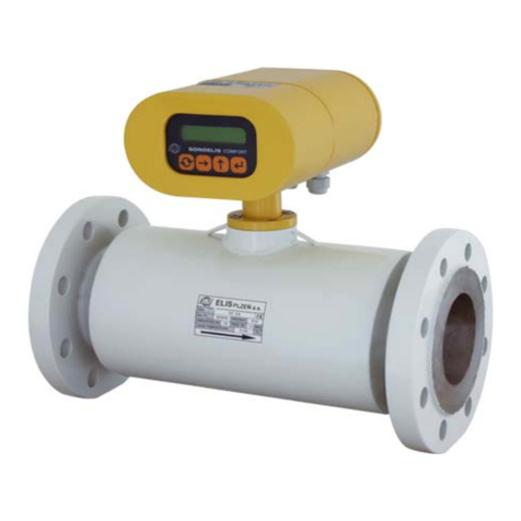
Elis SONOELIS SE 4015 Manual

Productapplication, installation and service manual
ELIS PLZE a. s.
UltrasonicFlowMeterSONOELIS SE4015and SE 4025 Page1of44
ELISPLZE a. s.,Luční15, P. O. BOX 126,30426Plzeň, CzechRepublic, tel.: +420/377 517711, fax:+420/377 517 722 Es90 337K/c
UltrasonicFlow Meter
SONOELISSE 4015
SE 4025

Productapplication, installation and service manual
ELIS PLZE a. s.
UltrasonicFlowMeterSONOELIS SE4015and SE 4025 Page2of44
ELISPLZE a. s.,Luční15, P. O. BOX 126,30426Plzeň, CzechRepublic, tel.: +420/377 517711, fax:+420/377 517 722 Es90 337K/c
CONTENT
1.APPLICATION..................................................................................................................................................................4
2. MEASUREMENTPRINCIPLE..........................................................................................................................................4
3. TECHNICALDESCRIPTION............................................................................................................................................4
3.1Generalinformation......................................................................................................................................................4
3.2Design specifications....................................................................................................................................................5
3.2.1Sensordimensions................................................................................................................................................5
3.2.2Electronicunit box dimensions...............................................................................................................................6
3.2.3Ultrasonicsensor..................................................................................................................................................6
3.2.4Electronicunit.......................................................................................................................................................7
3.2.5Flowmeterhandling..............................................................................................................................................7
4. TECHNICALSPECIFICATIONS......................................................................................................................................8
5. PROJECTDESIGN AND METER INSTALLATION.......................................................................................................10
5.1Project design ofsystemsincluding ultrasonicflow meters...........................................................................................10
5.2Assembly...................................................................................................................................................................13
5.2.1Generaldirections...............................................................................................................................................13
5.2.2Mechanicalconnections......................................................................................................................................13
5.2.3Electricalconnections..........................................................................................................................................13
5.2.4Productmarking..................................................................................................................................................13
5.2.5Sealing oftechnologicalmeters...........................................................................................................................13
6.Operational startandcontrol of themeterfunctions................................................................................................13
6.1Operational start.........................................................................................................................................................13
6.1.1Display data........................................................................................................................................................13
6.1.1.3Displayof measureddata..............................................................................................................................13
6.1.2Review ofthemeasured quantities......................................................................................................................13
6.1.3Review ofthemeasured quantityunits.................................................................................................................13
6.1.4Unit conversion table...........................................................................................................................................13
6.2Keyboardcontrolfunctions..........................................................................................................................................13
6.2.1Datadisplay mode..............................................................................................................................................13
6.2.1.1Volumeflow rate...........................................................................................................................................13
6.2.1.2Relativevolumeflowrate..............................................................................................................................13
6.2.1.3Massflowrate..............................................................................................................................................13
6.2.1.4Relativemassflowrate.................................................................................................................................13
6.2.1.5Volume.........................................................................................................................................................13
6.2.1.6Volume+......................................................................................................................................................13
6.2.1.7Volume-.......................................................................................................................................................13
6.2.1.8Mass............................................................................................................................................................13
6.2.1.9Mass+.........................................................................................................................................................13
6.2.1.10Mass-........................................................................................................................................................13
6.2.1.11Temperature...............................................................................................................................................13
6.2.1.12Density.......................................................................................................................................................13
6.2.1.13Sound propagationvelocity.........................................................................................................................13
6.2.1.14Fluidflow velocity........................................................................................................................................13
6.2.1.15Startofthemeasurementperiod..................................................................................................................13
6.2.1.17Durationoffailurecondition.........................................................................................................................13
6.2.1.18Powerfailureperiod....................................................................................................................................13
6.2.2Parametersetting mode......................................................................................................................................13
6.2.2.1Password.....................................................................................................................................................13
6.2.2.2Meter settingprocedures...............................................................................................................................13
6.2.2.3Languageselection.......................................................................................................................................13
6.2.2.4Measuring unit selection................................................................................................................................13
6.2.2.5.Newpassworddefinition..............................................................................................................................13
6.2.2.6Initialquantityselection.................................................................................................................................13
6.2.2.8Resettingaggregatequantities......................................................................................................................13
6.2.2.9.Meter zerosetting........................................................................................................................................13
6.2.2.10Endof parameter setting.............................................................................................................................13
6.3Automatedmetertest.................................................................................................................................................13
7.WARRANTYAND POST-WARRANTYSERVICES......................................................................................................13
7.1Warrantyservices.......................................................................................................................................................13
7.2Post-warrantyservices................................................................................................................................................13

Productapplication, installation and service manual
ELIS PLZE a. s.
UltrasonicFlowMeterSONOELIS SE4015and SE 4025 Page3of44
ELISPLZE a. s.,Luční15, P. O. BOX 126,30426Plzeň, CzechRepublic, tel.: +420/377 517711, fax:+420/377 517 722 Es90 337K/c
8. TESTING.........................................................................................................................................................................13
9. ORDERING.....................................................................................................................................................................13
10. PACKAGING................................................................................................................................................................13
11. PRODUCTACCEPTANCE..........................................................................................................................................13
12.WARRANTYCONDITIONS..........................................................................................................................................13
13. ORDER NUMBER........................................................................................................................................................13

Productapplication, installation and service manual
ELIS PLZE a. s.
UltrasonicFlowMeterSONOELIS SE4015and SE 4025 Page4of44
ELISPLZE a. s.,Luční15, P. O. BOX 126,30426Plzeň, CzechRepublic, tel.: +420/377 517711, fax:+420/377 517 722 Es90 337K/c
1.APPLICATION
The SONOELIS ultrasonicflowmetersofthe typeseries SE 4015/SE 4025 areintended for measurementsof
instantaneousflow rateandthetotalvolumepassedthroughfully-floodedpipingofalarge diameter.Themeter
configuration includesbothhardwareandsoftwareforcommunication withhigher-levelcontrolsystems.
The measurementmethod used issuitableformeasurementoffluidspermitting propagation ofultrasonicwaves
includingelectricallynon-conductivefluids.Toensurehigh measurementprecision,themetersarecalibrated on atest
stand.
FlowmetersSONOELISareused withone-beam(SE 4015)ordouble-beam(SE 4025)ultrasonicsensor.
2. MEASUREMENTPRINCIPLE
The meterusesthe “transit-time”impulsemethodwherethetimeneededforthe ultrasonicsignaltopassthe
distancebetweentheprobesimbeddedin thefluidpiping ismeasuredandevaluated.Toeliminateanyerrordueto
asymmetricplacementofthe ultrasonicprobes, the ultrasonicrayissent inturnsinand against thefluidflowdirection.
3. TECHNICALDESCRIPTION
3.1Generalinformation
The SONOELISSE4015/SE 4025 ultrasonicflow meterisanelectronicdeviceused forthe fluidflow
measurementsinafullyfloodedpiping.It consistsoftwo parts:theflowsensortobe installedon thepipingand
associatedelectronicunit, usuallyattachedtoaverticalplateorwall andinterconnected withthesensorbyacable.
The SE 4015/SE 4025 flowmeterscanbeused withinpiping systemsofrateddiameterbetween DN 200andDN
1200 wherethe metersintended forpipingsizesDN 200toDN 500 haveaslantof the probesunderthe angle a=45o
andthoseforpipingsizesDN600 toDN1200haveaslantofthe probesundertheangle a=60o(seethe drawing
below):
DN 200÷DN500DN 600÷DN1200
Fig.1The ultrasonicrayanglewithrespect tothe pipingaxis
Initsstandardconfiguration,theflowmeterincludesonefrequency andone impulseoutput, electricallyinsulated
fromthe restofthemetercircuitry.Oncustomer’srequestthemetercan beprovided withvariousoptionaldevices
suchasinterfacetotheRS485communication lineorinsulatedcurrentoutput. Upon adding the Pt100resistance
sensormeasuring the fluidtemperature, it ispossible,based on the measuredfluidvolume, tocalculatethemassofthe

Productapplication, installation and service manual
ELIS PLZE a. s.
UltrasonicFlowMeterSONOELIS SE4015and SE 4025 Page5of44
ELISPLZE a. s.,Luční15, P. O. BOX 126,30426Plzeň, CzechRepublic, tel.: +420/377 517711, fax:+420/377 517 722 Es90 337K/c
fluidpassedthroughthepiping. Inanotheroptionalconfigurationthemetercan measurethefluidflowinbothdirections
andindicatethe actualfluidflowdirection.
Onrequest, themetersensorcanbesuppliedinanIP68housing.
3.2Designspecifications
3.2.1 Sensor dimensions
D
DN
Fig.2Dimensionalsketchof the metersensor
DN 200 250 300 350 400 450 500 600 700 800 1000 1200
NPS 8“10“12“14“16“18“20“24“28“32“40“48“
L
[mm] 600 650 700 750 800 850 900 700 800 850 1000 1150
D
[mm] 340 395 445 505 565 615 670 780 895 1015 1230 1455
Weight
[kg] 41,553,568 89 113 136 161 182 292 378 632 978
Table1Sensordimensions

Productapplication, installation and service manual
ELIS PLZE a. s.
UltrasonicFlowMeterSONOELIS SE4015and SE 4025 Page6of44
ELISPLZE a. s.,Luční15, P. O. BOX 126,30426Plzeň, CzechRepublic, tel.: +420/377 517711, fax:+420/377 517 722 Es90 337K/c
3.2.2 Electronic unit box dimensions
M4
210
230
10
115
217
193
138
64
85
OFFICIALSEALS
INSTALATIONSEALS
SONOELIS
ELIS PLZENa.s.
COMFORT
4xO5,5
Fig. 3Dimensionalsketchofthe electronicunit box
3.2.3 Ultrasonic sensor
The sensorbodyisaweldedpiececonsistingoftwo endflangestobeconnectedtothepiping,themainpipe
sectionandtwo pipebranchesholdingthe ultrasonicprobes(see Fig.4).Inthe standardsensorversionthebodyis
designed foroperatingpressurePN10,made ofhigh-qualitysteeland theflangesareaccordingtostandard ČSNEN
1092-1; thewholeassemblyiscoatedwithpowderepoxypaint KOMAXIT E2310 oflight greyhue (RAL7035).
Onspecialrequest, the sensorbodycan be supplied: -inastainless-steelversion
-withANSI orJISflanges
-inversion forPN16orPN25(pipingsizesup toDN500)
Sensorsforapplicationindrinking-watersupplysystemsarecoatedwithpowderepoxypaintKOMAXIT E2110of
blue hue(RAL5017).
FLOWSENSOR
RATINGPLATE
ULTRASONIC
PROBE
FLOWDIRECTION
Fig. 4Ultrasonicsensor-description

Productapplication, installation and service manual
ELIS PLZE a. s.
UltrasonicFlowMeterSONOELIS SE4015and SE 4025 Page7of44
ELISPLZE a. s.,Luční15, P. O. BOX 126,30426Plzeň, CzechRepublic, tel.: +420/377 517711, fax:+420/377 517 722 Es90 337K/c
3.2.4 Electronic unit
The flow-meterelectronicunit(seeFig.5)isembeddedinaplasticboxwithasteelsheetattachedatthebackfor
verticalmounting.Atthefrontpanelonthe boxtherearemetertype designationand productname,productionseries
number,manufacturer’snameand logo,two-lineback-lighteddisplayunitandamembranekeyboard.Atthebottomof
the boxunderaremovableplasticcoverareplasticgrommetsforcablesof circularcross-section(one PG9andsixor
seven PG7grommets).The grommetsareintendedfortightfitting of cablesof externaldiameter6to8mm (PG9)and
4to6mm (PG7).Atthe bottomofthe boxthereisalsoan earthingbolt. Boththefrontpanelandtheterminalboard
covercan besealed.Instead ofonePG7grommetitispossibletofitafour-poleconnectorfortheRS485
communication line.
IMPORTANT NOTICE: Priortoputting themeterin operation, check thepropertighteningofall grommetswithcables
andblinding ofthe unusedones.
IMPORTANT NOTICE: The electronicunitshall notbe exposedtodirectsunlight.
PUSH-BUTTONS
PLASTIC COVEROF
THE TERMINALSTRIPS
GROUNDING
DISPLAY
LOCKING
PIN
FRONTPANEL
MECHANISM
OFFICIALSEALS
INSTALATION SEALS
SONOELIS
ELISPLZENa.s.
COMFORT
Fig. 5Electronicunit –description
3.2.5 Flowmeter handling
The arrowsindicate thecorrectmanner ofthe metersensorhandling.Lift the sensorbodyholding itbythe
handling eyesscrewed intobothflanges(see Fig.6).

Productapplication, installation and service manual
ELIS PLZE a. s.
UltrasonicFlowMeterSONOELIS SE4015and SE 4025 Page8of44
ELISPLZE a. s.,Luční15, P. O. BOX 126,30426Plzeň, CzechRepublic, tel.: +420/377 517711, fax:+420/377 517 722 Es90 337K/c
Fig. 6Correct gripon the metersensor
4. TECHNICALSPECIFICATIONS
Using Table2,select thecorrectsensorsizewithrespecttothe required measuring range.
The datainthe Tablearetaken fromstandard ČSNEN14154-1.
Table2Rangesofmeasured valuesforgiven piping sizes
Rated piping sizeDN 200 250 300 350 400 450 500 600 700 800 1000 1200
m
3
/h 1015,63202531,2539,38
5062,578,75100156,3200
Q1
Minimumflowrate
G/min
4468,888,1110138173220275347440688881
m
3
/h 16253240506380100126160250320
Q2Transient
flowrate G/min
70,411014117622027735244055570411001410
m
3
/h 8001250160020002500315040005000630080001250016000
Q3
Steady-stateflow
rate G/min
352055007050881011000
13870 1761022000
27740 35220
5503570450
m
3
/h 10001563200025003125393850006250787510000
1562520000
Q4
Overload flowrate
G/min
44006880881011000
13760
17340 2201027520
34670 44030
6882088060
m
3
/h 2,33,6 5,1 7,0 9,1 11,514,220,427,836,256,581,5
QNEC
Thresholdflow
rate G/min
10,115,922,530,840,050,662,590,0122159249359
l/imp 50501001001002002002002505005001000
Pulseoutput
constant k i G/imp
101020202020454555100100200

Productapplication, installation and service manual
ELIS PLZE a. s.
UltrasonicFlowMeterSONOELIS SE4015and SE 4025 Page9of44
ELISPLZE a. s.,Luční15, P. O. BOX 126,30426Plzeň, CzechRepublic, tel.: +420/377 517711, fax:+420/377 517 722 Es90 337K/c
The thresholdflowrate(QNEC)isthe minimumflowrateatwhichthemeterstartstoindicateandprocessthe fluid
flowparameters.Atthe manufacturer’splant, QNEC issetatavalue correspondingtothe flowvelocityof20mm/s.On
customer’srequest , thethresholdflowratecan be set atanyvalue withinthe rangeofQNEC = 0.1 ¸25%Q4.
The maximumpermitted errorinfluidvolumemeasurementsatflowratesbetweenQ
1 (including)and Q
2
(excluding)is:5% irrespectiveofthe fluidtemperature.
The maximumpermitted errorinfluidvolumemeasurementsatflowratesbetweenQ
2 (including)and Q
4
(including)is:1% forthefluidtemperaturenotexceeding 50°C, and
3% forthefluidtemperaturegreaterthan 50°C.
Piping I.D. DN 200÷DN1200
Rated pressure PN10, onrequest PN16orPN25 forpiping sizesDN200 ÷DN 500
Measurement precision
±1% forflowrateQ > Q2 (seeTable2)andfluidtemperatureup to50°C(SE 4015)
±0,5%forflowrateQ > Q2 and fluidtemperatureup to50°C(SE4025)
Fluidtemperature 0÷+150°С
Ambienttemperature 0÷+50°С
Ambientrelativehumidity notexceeding 80%
Storage temperature -10 ÷+70°C
Visualoutput via two-line16-characteralphanumericLC displayunit
Powersource 90 ÷260V, 50/60Hz
Back-up powersource Libattery 3V(lifetime5years)
Powerrequirement 6VA
Line fuse T 250mA, 250V
Protection againstelectric
shock according to
standard ČSN332000-4-
41
automaticdisconnection frompowersourceinthe TN–Snetwork
Protect. class;electronic
unit IP65
Protect. class;sensor,
probes IP54 (on request IP68)
Outputs(insulated by
meansimpulseoutput,0.1÷10,000 l/imp, impulselength50ms
of optocouplersfrequency output 0÷1,000Hz(corresponding toflowrates0÷Q4)
relayoutput24VAC/0.1A
RS485 line
Optionalaccessoriesinsulated current output 0/4÷20mA(corresponding toflowrates0÷Q4)
mass flowrateinformation
flow-ratemeasurementsinbothdirections,flowdirectionindication
extended range offluidtemperature(upto+180°C)
sensorprotection class IP68
drinking-watermeterversion
sensorflangesaccording toalternativestandards(ANSI, JIS)
Table3SE 4015/SE 4025 flowmeterspecifications

Productapplication, installation and service manual
ELIS PLZE a. s.
UltrasonicFlowMeterSONOELIS SE4015and SE 4025 Page10of44
ELISPLZE a. s.,Luční15, P. O. BOX 126,30426Plzeň, CzechRepublic, tel.: +420/377 517711, fax:+420/377 517 722 Es90 337K/c
5. PROJECTDESIGN AND METER INSTALLATION
5.1Project design ofsystemsincludingultrasonicflow meters
Indesigninganyprojectitisnecessarytoobservespecificrulesconcerningplacementofthe metersensorsin
pipingsothatthemeasuringprecision wouldnot beadverselyaffected.Inthecaseof theSONOELICflowmeters,the
requiredlengthsofstraightpipingsectionsbeforeand afterthe metersensorare5DN and 3DN,respectively(seeFig.
7).
FLOWDIRECTION
3 DN5DN 5DN 3DN
FLOWDIRECTION
Fig. 7Minimumlengthsofstraight piping sectionsFig. 8Minimumlengthofstraight piping sectionat
the inputsideofclosingvalve
Ifthereisapumpnearthemetersensor,itshouldbelocatedatthedistanceofatleast20DN fromthesensor
output (seeFig. 9).
20 DN
FLOW DIRECTION
Fig. 9Minimumlengthofstraight piping sectionbeforeapump
Incaseswherecompleteflooding ofthe piping cannotbe guaranteed atall times,themetersensorshouldbe
locatedsoastoensuremeeting ofthiscondition (see Fig. 10).
FLOWDIRECTION
5DN3DN
FLOWDIRECTION
3DN
5DN
Fig. 10 Sensorlocationsensuringcompletefloodingatall times
Ifthe sensoristobefitted intoaverticalpipingsection,thefluidflowdirectioninsuchsectionshall beupwards(see
Fig. 11).

Productapplication, installation and service manual
ELIS PLZE a. s.
UltrasonicFlowMeterSONOELIS SE4015and SE 4025 Page11of44
ELISPLZE a. s.,Luční15, P. O. BOX 126,30426Plzeň, CzechRepublic, tel.: +420/377 517711, fax:+420/377 517 722 Es90 337K/c
FL OW D IR E CTIO N
Fig. 11 Sensorfitted intoaverticalpiping section
Errorlessmeteroperationcannotbeguaranteedunless the sensoriscompletelyfilled withthemeasuredfluidatall
times.Thereforethesensorshouldnotbelocatedatthehighestpipingsectionsorinverticalpipingsectionsif the fluid
flowdirection isdownwards,inparticularinsituationswherethereisapipingoutletintoopen reservoirsortanks
anywherenear(seeFig. 12).
FLOW DIRECTION
FLOW DIRECTION
Fig. 12 Examplesofincorrectsensorplacement
Anotherfactorthatmayinfluencethe meterfunctionisthesensoranglepositionwithrespecttoitslongitudinalaxis.
Occasionalairbubblesinthepiping maygetcaughtinthe hollowwelded-on probeholderswheretheywoulddisrupt
the measuringprocess.Toeffectivelypreventthisfromoccurring,thesensorprobesshould bestbein thehorizontal
plane(seeFig.13a).Ifforanyreason suchposition isnotpossible,thesensorbodymaybe fitted inangularposition
wheretheprobeplane and horizontalplaneforman angleofnotmorethan 30°. Theprobesplanesofdouble-beam
sensors(SE4025)andverticalplaneforman angle45°(see Fig.13b)

Productapplication, installation and service manual
ELIS PLZE a. s.
UltrasonicFlowMeterSONOELIS SE4015and SE 4025 Page12of44
ELISPLZE a. s.,Luční15, P. O. BOX 126,30426Plzeň, CzechRepublic, tel.: +420/377 517711, fax:+420/377 517 722 Es90 337K/c
30°
30°
PROBE 1 PROBE 2
Fig. 13 Permitted range of one-beamsensorrotation withrespect toitslongitudinal axis(SE4015)
45°
45°
PROBE 1 PROBE 4
PROBE 3 PROBE2
Obr. 13b Angelbetween probesplanesand verticalplane at double-beamsensor(SE 4025)

Productapplication, installation and service manual
ELIS PLZE a. s.
UltrasonicFlowMeterSONOELIS SE4015and SE 4025 Page13of44
ELISPLZE a. s.,Luční15, P. O. BOX 126,30426Plzeň, CzechRepublic, tel.: +420/377 517711, fax:+420/377 517 722 Es90 337K/c
5.2Assembly
5.2.1 General directions
Inmeterassembly/fitting, strict observanceofthe guidelinesand principlesgiven inthismanualisnecessary.
The meterinstallationshall be incompliancewiththe requirementsofstandard ČSNEN14154-2, chapter5.
Topreventundesirable electromagneticinterference,thepowercablesshall belaid atleast25cmawayfromthe
metersignalwires.Anysignalwireconnectionsshall bedonebysoldering andthe soldered jointsshall be protected
againstclimaticand mechanicalstressesbymeansofsuitableinstallation boxes.All cablesshall be leadoutside
thermalinsulationlayersonpiping(ifany).ConnectionstothePt100temperaturesensor,currentoutputandRS485
communication interfaceshall bedonebyshielded wires.The shielding shall be earthedatonlyoneend (connected to
the respectiveterminalontheX1terminalstripin the meterelectronicunit).Shieldedconductorsarealso
recommendedtobe used atthefrequencyand impulseoutputs.The shielding shall be earthed atoneend only,inthis
caseontheside ofthe higher-levelcontrolsystem.
Bothmeterpartsneedbeproperlyearthed.Useearthing conductorof cross-sectionof atleast4mm2toconnectthe
earthingboltson the electronicunitboxandtheflowsensorbodyasshown inFig. 14..
DIRECTION
ELISPLZENa.s.
PROBE2
PROBE1
FLOW
SONOELIS
COMFORT
min.4mm
2
Fig. 14 Earthing ofthe electronicunit andflow-metersensor

Productapplication, installation and service manual
ELIS PLZE a. s.
UltrasonicFlowMeterSONOELIS SE4015and SE 4025 Page14of44
ELISPLZE a. s.,Luční15, P. O. BOX 126,30426Plzeň, CzechRepublic, tel.: +420/377 517711, fax:+420/377 517 722 Es90 337K/c
IMPORTANT NOTICE: Inthe casesofoutdoorinstallation, the electronicunit shall byprotected fromdirect sunlight
bymeansofasuitablesun blind.Onthe otherhand, itshall not placed intoan unventilated cabinet.
5.2.2 Mechanicalconnections
The ultrasonicsensorshall be fitted intothe fluidpiping bymeansofflangesensuringexactmatchwiththe
respectivecounter-flangesonthe piping ends(seethespecificationsonthe flange circumference).Unlessrequired
otherwise,thesensorshall be supplied withflangesaccording tostandard ČSNEN1092-1(thealternativesolutions
areANSIorJISflanges).
5.2.3 Electrical connections
Removethe coverheldin placebytwo M4screwsatthe bottompart of the frontpanelonthe electronicunitboxto
gainaccesstotheterminalsandconnectorsforexternalelectricalconnectionstothe unitasshown inthe following
figure:
SWITCHING
L1 NPE
100V-250V
50/60Hz
24V AC/0,1A
BOTTOMBOARD
5
4
7
2
8
10K
CANON 9
RS232
X4
6
1
9
5
10K
:
+24V
W4W5
W6 GND
IZ
VOLUME
RESET
3
6
1
+ +
-
20mA
CURR ENT
20mA )
19161817141513
+ -
PULSE
OUTPUT
OUTPUT
(
4 -.
0 -
.
.
.
FREQVEN.
OUTPUT
OUTPUT
PROBE 1
PROBE 2
RS 485
611 12108 97
+-
5
X1 342
PE 1
PENU
Pt100
S1
X6 21543
Fig. 15aSchematicdrawingofconnectionstothe SE 4015 ultrasonicflowmeter

Productapplication, installation and service manual
ELIS PLZE a. s.
UltrasonicFlowMeterSONOELIS SE4015and SE 4025 Page15of44
ELISPLZE a. s.,Luční15, P. O. BOX 126,30426Plzeň, CzechRepublic, tel.: +420/377 517711, fax:+420/377 517 722 Es90 337K/c
345
12
50/60Hz
100V-250V
L1
U
X1
PE
N
:
SWITCHING
24V AC/0,1A
OUTPUT
Pt100
PEN
X6
1
PE 2
6X4
87
5
OUTPUT
16
PROBE 4
9
PROBE 2
PROBE 1
PROBE 3
643 5 7 8
- +
RS 485
OUTPUT
FREQVEN. PULSE
1110 12
+
1413
+
15
VOLUME
BOTTOMBOARD
-
+
.
.
0 - 20mA
OUTPUT
CURRENT
.
4 -
( 20mA)
.
RS232
CANON9
19
-
17 18
1
6
RESET
S1
9
5
0K
3421
W6
W5
0K1
W4
1
+24V
GND
IZ
Fig. 15bSchematicdrawingofconnectionstothe SE 4025 ultrasonicflowmeter
Notethe connectionsofprobes1and 2(1,2,3and 4atSE 4025), necessary forthe correctmeteroperation. For
probe marking see Fig. 13.
ConnectedtoterminalstripX1are,apartfromthe ultrasonicprobes,thefeedingpowerlines,signaloutputs(the
impulse, frequency,current and relayoutputs) and the RS485communicationinterface.
The X4CANON9connectorservesthepurposeofconnectingtheRS485interfaceusedin themetercalibration,
servicing and in-companyoperationalsetting.
The X6terminalstripisusedtoconnectthePt100temperaturesensorinthe optionalmass-flow-ratemeter
configuration.
By shortingthe jumpersW4andW6the impulseoutputwill beactivated;the sameactiononjumpersW5and W6
activatesthefrequency output. If the impulseorfrequencyoutputsareusedinthe passivemode of operation(jumpers
W4throughtoW6disconnected),theoptroncurrentshall notexceed20mA.TheS1push-buttoncanbeusedtoreset
the totalfluidvolumereading tozero;thesamecommand canbesentviathe RS485 line.Toindicatethefluid flow
direction,connecttoterminals1and 2onterminalstripX1arelaycoil inserieswithexternalalternatingvoltage source
24 V/100mA.
Pushthe arresting pinon theright-handsideofthe electronicunitboxupwardsand liftoffthe frontpaneltothe left
togainaccess toswitchS3through the respectivecircularholeinthetopprintedcircuit boardofthe unit.

Productapplication, installation and service manual
ELIS PLZE a. s.
UltrasonicFlowMeterSONOELIS SE4015and SE 4025 Page16of44
ELISPLZE a. s.,Luční15, P. O. BOX 126,30426Plzeň, CzechRepublic, tel.: +420/377 517711, fax:+420/377 517 722 Es90 337K/c
SwitchesS2andS3–location and functions
Fig. 16 Location ofswitchesS2andS3
Flow metermodeofoperation Information on thedisplayunitCombination ofswitch positions
MeasurementInstantaneousflowrate
MeasurementInstantaneousvelocity
Programming EEPROMprogramming
Servicing Service
The servicing mode isreserved forthe purposesofmeterproduction andspecialservicesbythemanufacturer.
5.2.4 Product marking
Meterrating plate (located on the electronicunit box):
Manufacturer
Productionseriesnumber
Type certification
Electromagneticcompatibilityclass(EMC)
Environment protectionclass
Ambient temperature
Communication address
LimitflowratevaluesQ1, Q3, Q4

Productapplication, installation and service manual
ELIS PLZE a. s.
UltrasonicFlowMeterSONOELIS SE4015and SE 4025 Page17of44
ELISPLZE a. s.,Luční15, P. O. BOX 126,30426Plzeň, CzechRepublic, tel.: +420/377 517711, fax:+420/377 517 722 Es90 337K/c
Outputsignalsand calibration information
Listofsystemcomponentsincluding typedesignationandproductionseriesnumbers
Systemproduction seriesnumber/ yearofmanufacture
Listofall systemcomponentsincluding type designation,quantityand productionseriesnumbers
Electronicunitrating plate (located on the electronicunit box):
Manufacturer
Type designation
Productionseriesnumber/ yearofmanufacture
Powersource
Protection classinformation
Flow sensorrating plate (located on the flowsensorbody):
Manufacturer
Productionseriesnumber/ yearofmanufacture
Type designation
DN information
Fluidtemperaturerange
Rated pressurePN
Fluidflowdirection
Protection classinformation
5.2.5 Sealing of technological meters
The SONOELISflowmetersareprovided withclampingandstick-on factory andassemblyseals–see Fig.5.
Shouldthefactorysealsbefoundremoved ordamaged,the productwarrantyshall be void.
6. Operational startand controlof themeterfunctions
6.1Operationalstart
6.1.1 Displaydata
6.1.1.1Connecting themeter
The first threesecondsafterconnectingthemetertothepowersourcethedisplayreads
Flowmeter
ELI S
6.1.1.2 Meterstatusinformation
Inthe normaloperation,thesymbolappearing atthe last digitposition on thesecond line informsaboutthecurrent
mode ofoperation ofthe signalprocessingelectronicunit. The charactersusedand theirmeaningsareasfollows:
I electronicunit initialisation
+ measurementsinthe positiveflowdirection
-measurementsinthe negativeflowdirection
Ccalculationofmeasuredvalues,outputsignalgenerationanddisplay
Wstand-bymode
Tdatacommunication(databeing sent).
Obr.
26

Productapplication, installation and service manual
ELIS PLZE a. s.
UltrasonicFlowMeterSONOELIS SE4015and SE 4025 Page18of44
ELISPLZE a. s.,Luční15, P. O. BOX 126,30426Plzeň, CzechRepublic, tel.: +420/377 517711, fax:+420/377 517 722 Es90 337K/c
Undernormaloperating conditionsthe abovecharactersregularlyreplaceone another.Inthecaseof
an errordue toasensorfailure,loss ofasensorsignaldue toacablefailure,presenceofanairbubbleor
amechanicalparticleinthe fluidflow,an“R”will appearatthe lastposition on the firstline andthe“I”and“+”signswill
appearinturnsatthe lastposition on the second line ofthe displayunit. Afailureofthe electronicunitwill usuallybe
manifestedbydiscontinuedregularchangesofthe systemstatussymbolsonthedisplay.
6.1.1.3Display ofmeasureddata
Up tothree measured quantitiescanbe displayed simultaneously;oneon the firstline,andthe othertwointurns
on thesecondline ofthe displayunit. Theswitchingfrequencycan beselected intermsofthe numberofmeasuring
cyclesperdisplaytimeofone measuredquantity.
Mostoften thefirstdisplayline isusedtoshowthevolumeflowrate(inm3
/hod)orthemassflowrate(inmetric
tonsperhour),andtheseconddisplayline todisplaythetotalvolume(inm
3
)orthetotalmass (inmetrictons)
alternativelywiththe fluidtemperaturein°C.However,the customerisfree todefine othercombinationsofthe datato
be displayed and/ortoselectotheroptionaldataunitsfromthe softwaremenu available.
6.1.2 Reviewof the measured quantities
Volumeflowrate
Relativevolumeflowrate(in%ofqs)
Massflowrate [T]
Relativemass flowrate(in%ofqs) [T]
Volume(aggregatevalue)
Volume+ (volumeofthe fluidpassed inthe positivedirection) [O]
Volume-(volumeofthe fluidpassedinthenegativedirection) [O]
Mass(aggregatemass) [T]
Mass+ (massofthe fluidpassed inthe positivedirection) [T], [O]
Mass-(massofthe fluidpassedinthenegativedirection) [T], [O]
Temperature [T]
Density [T]
Sound propagation velocity
Fluidflowvelocitythrough the sensorflange
Start ofthe measurementperiod (dateand timeofthe last resetting command)
Duration ofthe measurement period
Duration ofametererrorcondition
Duration ofapowerfailureperiod
Date
Time
Comment:
Quantitiesdenoted [T]will onlybemeasured anddisplayedifthe meterconfigurationincludes
athermometer;quantitiesdenoted [O]requirethatthe flowmeterhasbeen setformeasurementsinbothfluid-flow
directions.

Productapplication, installation and service manual
ELIS PLZE a. s.
UltrasonicFlowMeterSONOELIS SE4015and SE 4025 Page19of44
ELISPLZE a. s.,Luční15, P. O. BOX 126,30426Plzeň, CzechRepublic, tel.: +420/377 517711, fax:+420/377 517 722 Es90 337K/c
6.1.3 Reviewof the measured quantityunits
VolumeflowrateMassflowrateVolumeMass
m3/hourt/hour1,000
m3 1,000
t
m3/mint/min m3
t
m3/st/s
l
kg
l/hourkg/hour1,000
bbl1,000
tons
l/minkg/min
bblton
l/skg/s1,000
ft3lb
bbl/hourtons/hour
ft3
bbl/mintons/min1,000
gal
bbl/stons/sgal
ft3/hourlb/hour
ft3/minlb/min
ft3/slb/s
gal/hour
gal/min
gal/s
TemperatureDensityVelocity
°C t/m3m/s
°F kg/m3ft/s
g/cm3
tons/m3
lb/ft3
Table4Reviewofthe measured quantityunits
Namesofselected units
bblAmerican barrelsSecond
ftFootminMinute
galAmerican gallon hourHour
ton American ton°CDegreeCelsius
lbPound °F DegreeFahrenheit
m3CubicmetertMetricton
lLitrekgKilogram
Table5Namesof selected units

Productapplication, installation and service manual
ELIS PLZE a. s.
UltrasonicFlowMeterSONOELIS SE4015and SE 4025 Page20of44
ELISPLZE a. s.,Luční15, P. O. BOX 126,30426Plzeň, CzechRepublic, tel.: +420/377 517711, fax:+420/377 517 722 Es90 337K/c
6.1.4 Unit conversion table
Volumeflowrate1m3/hour= 0.01666667m3/min
0.0002777778m3/s
1,000 l/hour
16.66667l/min
0.2777778 l/s
6.289387bbl/hour
0.1048231 bbl/min
0.001747052 bbl/s
35.31467ft3/hour
0.5885778 ft3/min
0.009809630 ft3/s
264.1708gal/hour
4.402846gal/min
0.07338077gal/s
Massflowrate1t/hour= 1.102311tons/hour
0.01837185tons/min
0.0003061975tons/s
2,204.623lb/hour
36.74371lb/min
0.6123952 lb/s
Volume1m3= 6.289387bbl
35.31467ft3
264.1708gal
Mass1t = 1.102311tons
2,204.623lb
Density1t/m3 =1.102311tons/m3
62.42797lb/ft3
Temperaturet
F =32 + 1.8tC
Velocity1m/s= 3.280840ft/s
Table6Unit conversion table
6.2Keyboardcontrolfunctions
The four-buttonkeyboardallowsforawide rangeofthe meterfunctionstobecontrolled andmodified withrespect
totherequirementsofparticularoperatingconditionsatthe user’splant.Thepush-buttonsT1toT4areprovided with
the following graphicsymbols:
T1
T2
T3
T4
The push-buttoncontrolofthe meterisshown in aschematicdiagramin Fig.17.Thesystemcanbeoperatedin
two differentmodeswheretheswitching-overactionbetweenthe operationmodesandindividualfunctionalblocks
withinaselected modecanbeinitiatedbydepressingthe push-button theimage ofwhichisdepictedatthegiven
transitionposition.Fromthediagramitfollowsthat
atransitionfromone block tothenextone(on theright-hand side)will be done bydepressingtheT2button,whilea
transitiontothepreviousblock(nexton the left-hand side)bydepressing the T3button.TheZeroResetblockcanonly
be activated in thecasesoftechnologicalmeters(thesoftwareswitchin the“NF”position).Inthecaseofcommercial
(invoicing)meters,wheretheswitchisinthe“F”position,the Zeroreset blockismissing.
Upon energising,the meterwill automaticallyadoptthe displaymode withthe pre-selected(initial)quantity
displayed (seedescriptionbelow).Thedisplaymodewill alsobecomeoperativeif no push-buttonhasbeen depressed
overthe periodof300measurementcycles(5minutesforameasurement cycleof1s).
This manual suits for next models
1
Table of contents
Other Elis Measuring Instrument manuals
Popular Measuring Instrument manuals by other brands

Tenma
Tenma 72-14435 user manual

Agilent Technologies
Agilent Technologies 85032B/E 50 User's and service guide

Evoqua
Evoqua WALLACE & TIERNAN P7 ADVANCED instruction manual
Hanna Instruments
Hanna Instruments HI84534 instruction manual
Austro Engine
Austro Engine AE300-Wizard user guide
MFJ
MFJ MFJ-860 instruction manual
