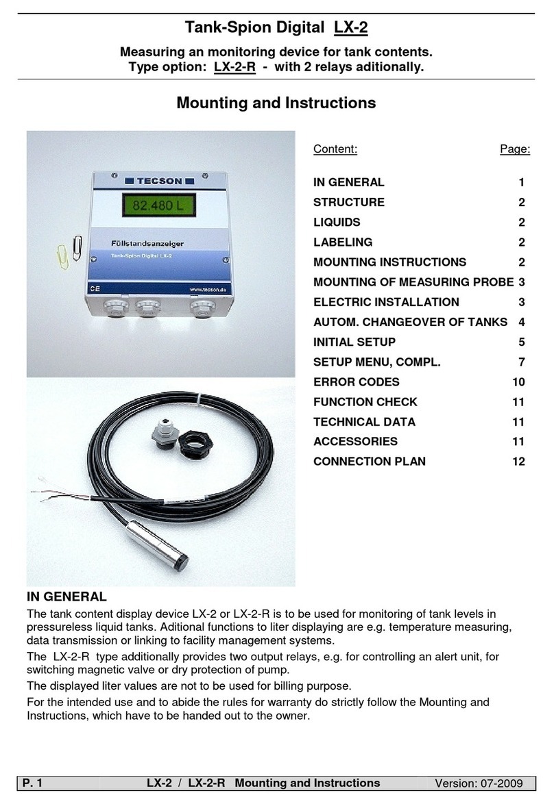
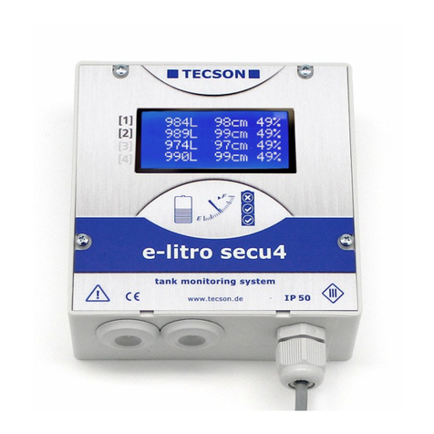
Tecson Tank-Spion Digital LX-NET User manual

01-2016 LX-(Q)-GSM / LX-(Q)-NET Techn. Docum. + Installation P. 1
Installation Instructions
and
Techn. Documentation
Electronic tank monitoring devices with data messaging
Tank-Spion Digital LX-NET
Tank-Spion Digital LX-GSM
Tank-Spion Quadro LX-Q-NET
Tank-Spion Quadro LX-Q-GSM
Content:
Page:
GENERAL
2
MOUNTING INSTRUCTIONS 3
MOUNTING OF LEVEL PROBE 3
ELECTRIC INSTALLATION 4
CONNECTION CLAMPS 5
DEVICE MESSAGES (SMS) 6
DEVICE PARAMETERS (SMS) 6
INITIAL SETUP 8
FUNCTION CHECK 9
MAINTANCE 9
NETWORK CONNECTION 10
BROWSER ACCESS 11
ERROR CODES 13
TECHNICAL DATA 15
LIQUIDS 15
ACCESSORIES 16
LABELING 16

P. 2 LX-(Q)-GSM / LX-(Q)-NET Techn. Docum. + Installation 01-2016
GENERAL
The electronical tank content display device of LX-Serie is to be used for monitoring of tank levels
in pressureless liquid tanks.
This documentation is to be used for the devices LX-GSM, LX-Q-GSM and LX-NET, LX-Q-NET.
Beside the liter monitoring several other functions are available, in most cases with an extra
module or adaptor. These functions are temperature measuring, data transmission or bindung to
facility management systems.
The devices LX-GSM and LX-NET provide an output relay. It operates automatically depending
on the tank filling level. Besides it can be operated by remote control (telecontrol). The relay is
able to control an alert unit, to switch a magnetic valve or to protect a pump from running dry. The
relay has opening and closing contacts for switching two separate current circuits.
Level probe:
Die Geräte-Sets LX-GSM und LX-NET werden jeweils mit 1 Tankmesssonde geliefert.
The LX-GSM and LX-NET sets are provided with 1 level probe each.
The LX-Q-GSM and LX-Q-NET types offer 4 measuring inputs for up to 4 level probes. They
monitor the individual content of each tank and total stock.
The level probe can be mounted by standard with a 1“ or 1½“ screw thread. For mounting in plas-
tic tanks a grommet and a PG-screwing is provided.
Electric supply: 230V AC.
A special type of the monitoring device for DC 24V or DC 12V can be delivered.
The monitoring device has a LCD display by 2 x 16 characters.
The indicated values are not calibrated for billing purposes.
For the intended operation and to adhere the warranty the following instructions for mounting and
use are to be followed and to be handed over to the user.
Device types:
The Q (quadro) device types provide 4 measuring inputs but no output relay.
The other device types provide only 1 measuring input and one output relay.
LX-GSM + LX-NET:
These sets are usually delivered with one standard measuring probe.
LX-Q-GSM + LX-Q-NET:
These ’Quadro’ sets are presented usually without measuring probes.
LX-GSM + LX-Q-GSM:
Additionally to liter monitoring these device types report the status by SMS.
They need a SIM card for mobile network. Prepaid is recommended.
The SIM card is not included.
The recipient can either be a mobile phone or the www.oilview.de system.
LX-NET + LX-Q-NET:
These device types have a LAN jack (RJ45) for direct Ethernet connection.
Your browser gets a HTML data page from the device. For calling the
data page from Internet the router port must be forwarded.
Data binding to www.oilview.de web server is available too.

01-2016 LX-(Q)-GSM / LX-(Q)-NET Techn. Docum. + Installation P. 3
MOUNTING INSTRUCTIONS
Only qualified persons are allowed to install the measuring probe and to connect the display de-
vice. Follow the regulation for each liquid, especially for the risk of water pollution and for flam-
mable liquids.
Condition for proper operation of measuring device is a professional installation. Follow the tech-
nical rules for planning, construction and operation of the entire facility.
Additionally follow the rules of preventions of accidents by the government safety organizations
and the instructions of mounting and operation of the storage tanks too.
•Condition for proper operation is a pressureless storage tank. The tank must have proper
ventilation. Oil tanks and gasoline tanks must be equipped with a level limiter.
•The cable entry in the tank has to be made watertight and vapor tight appropriately.
•The measuring probe and display device are not securety devices. They do not replace the
level limiter of a tank.
•Installation of the display device in explosive zones is not permitted.
Ask for an EEx-probe with Zener barrier. The tank level probe must be mounted inside the
tank with a cable protection pipe.
•230V AC: The display device is connected to the power supply. Operating is only permitted
with closed box lid.
•Type 230V AC :
The display device is connected to the power supply system and may normally only to be
used with box cover closed.
•Type 12V / 24V DC:
As a special model this device type is supplied by a low voltage power supply of 24 V
(DC 20V-28V) or 12V (DC 11V-15V).
In case of inappropriate installation you lose any warranty.
MOUNTING OF LEVEL PROBE
•
In case of cellar steal tanks or subgrounded tanks use the included screw-
ing joint for mounting the measuring probe.
•If an old fuel gauge was used dismount it and use the tank screwing port.
•Subgrounded tanks normally provide an idle screwing port. Dismount the
dummy screwing.
•If there is no other appropriate opportunity the measure probe can be
installed in the bearing pipe. We recommend the use of a 1“ T pipe collar
with a 1“ nipple for the head of the bearing pipe.
The cable of the measuring probe comes out of the T pipe collar on the
side. Occasional bearing for control parallel to the cable of the measuring
probe is still possible.
Mounting:
•Switch off the oil burner and lock the suction pipe if necessary.
•Clear the screwing port of the tank.
•Put the cable of the probe through the screwing joint. Put the measuring
probe into the tank.
•Mount the screwing joint with PTFE sealing tape.
•Sink the measuring probe down to the ground of the tank. Fix the cable
with the PG screwing. The measuring probe may optionally lay or stand on
the ground of the tank.
•Zero-point calibration is normally not required..
•If necessary unlock the suction pipe, switch on the oil burner and check
the functions.

P. 4 LX-(Q)-GSM / LX-(Q)-NET Techn. Docum. + Installation 01-2016
Probe box :
To be used
- outdoors
- in manhole pit (buried tanks)
- in damp locations.
The probe box must be wa-
tertight and ventilated
(for pressure balance of the
hydrostatic level probe).
ELECTRIC INSTALLATION
Interconnection of measuring probe to display device
Probe supply: Low-voltage DC
Connection: Connect the 2-wire probe cable as follows:
Red(+) => clamp 1 , Black (-) => clamp 2.
Air capillary: The air capillary must have ventilation to atmosphere.
The end of the probe’s cable and the air capillary
must be protected against humidity.
Extension: The cable of the probe can be extended up to 100 m,
e.g. with NYM or YR (damp location) or NYY (soil).
Line diameter at least 2 x 0.4 mm².
In case of cable extension in a manhole pit or out-
doors it is recommended to use a waterproof clamp
box with special air pressure ventilation (accessories).
Shielding: Near to power lines it is recommended to use a
shielded probe signal line. (Cable shielding has to be
grounded.)
Supply voltage:
Voltage: AC 230 V, 50 Hz
Clamps: PE (protective conductor), N (neutral conductor),
L (phase).
Cable is not included in scope of delivery.
Refer to the figure on the
following page.
The capillary in the
probe’s cable must
have ventilation.
The capillary filter stays
attached!
Refer to probe instruc-
tions.
Caution:
Do never connect de-
vice type DC 24V or
12V to 230V.

01-2016 LX-(Q)-GSM / LX-(Q)-NET Techn. Docum. + Installation P. 5
CONNECTION CLAMPS
If LX-GSM
and LX-NET
Relay connection:
The LX-GSM and LX-NET devices do have a double output relay. By this relay two separate elec-
tric circuits can be switched simultaneously, e.g. a signalling device on/off and an electric
valve off/on too.
Under initial conditions the relay contacts 7-8 are closed and relay contacts 9-10 are opened.
In case of event the relay operates so both contact pairs switch over. Then contacts 7-8 do open
and 9-10 do close.
At power outage or when the device goes out of order then the relay is under initial condition. in
Inital state Event state
Relay output Contact 7 - 8 links
Contact 9 - 10 opened
Contact 7 - 8 opened
Contact 9 - 10 links
Schaltspannung
Max. 250 V AC
Voltage
Max. 3,5 A
Steuerfunktion
For setup see menu item “6. Relay“ and GSM command #S (at LX-GSM)

P. 6 LX-(Q)-GSM / LX-(Q)-NET Techn. Docum. + Installation 01-2016
For LX-Q-GSM :
For LX-GSM / LX-Q-GSM :
DEVICE MESSAGES (SMS)
See additional documention:
“ Messages, Commands a. Parameters ati GSM-Messenger, LX-GSM, LX-Q-GSM “
If the device will be linked to the www.oilview.de system for remote management then these
communication details via mobile phone are not relevant. The complete parameter setup will be
done via the OilView system.
DEVICE PARAMETERS (SMS)
See additional documention:
“ Messages, Commands a. Parameters ati GSM-Messenger, LX-GSM, LX-Q-GSM “
If the device will be linked to the www.oilview.de system for remote management then these
communication details via mobile phone are not relevant. The complete parameter setup will be
done via the OilView system.
pushbuttons SIM card Measuring probes 1 ( to 4 ) 230 V supply

01-2016 LX-(Q)-GSM / LX-(Q)-NET Techn. Docum. + Installation P. 7
For LX-NET / LX-Q-NET :
LX
-
NET connection clamps:
LX
-
Q
-
NET connection clamps:
Alarm input | Pushbuttons Measuring probes 1 ( to 4 ) 230V supply
Probe | Serial-Link-In | Digital-In (Alarm) Pushbuttons Relay conttact pairs 230V supply

P. 8 LX-(Q)-GSM / LX-(Q)-NET Techn. Docum. + Installation 01-2016
INITIAL SETUP
The initial setup is carried out after completed mounting.
Determine the tank data and enter them into the mode:
You find 3 push buttons (blue) on the PCB positioned between the connection clamps.
Press ENTER => Device enters the setup mode
Displayed step „1. Measur probe“
You can step through the menu items by pressing PLUS or MINUS.
Press ENTER to step into a sub-menu.
Press PLUS or MINUS for selection; press ENTER to confirm.
After completing Step 7 you reach „8. Exit“.
Press ENTER to exit the setup mode:
The device returns to the display mode and shows the current stock.
You find additional setup options in step 9 to 24, reachable by pressing PLUS.
Setup / Programming :
You find the complete documentation of the setup in the enclosed leaflet,
refer to
Setup and Operation

01-2016 LX-(Q)-GSM / LX-(Q)-NET Techn. Docum. + Installation P. 9
FUNCTION CHECK
After fueling or once a year please check if the displayed liters are correct.
MAINTANCE
It is recommended to check once year if the displayed liters are correct.
For a simple check lift the level probe by the cable so that the probe is above
the liquid level. In this state the device should display 0 liters (+tolerance).
In case of large deviation we recommend to do an Offset calibration for the
measuring probe again. Refer to the setup step “9.Offset probe” and if appli-
cable to the setup “10.Trim height“.
New level probe:
In case mounting of a new level probe it is necessary reset to “default values”
in step “9. Offset probe“.

P. 10 LX-(Q)-GSM / LX-(Q)-NET Techn. Docum. + Installation 01-2016
For LX-NET / LX-Q-NET :
NETWORK CONNECTION
Netzwork connection:
The LX-(Q)-NET device has a directly connectivety to
LAN/Ethernet network with 10 / 100 Mbit TCP/IP protocol.
Inside the housing you find the RJ45 jack for connecting a CAT-5
network cable. The plug of the network cable has to be pushed
through the inlet at bottom side of the housing.
Additional documentation:
See documentation “
Devices with n
etwork bindung
“.
The LX-(Q)-NET supports DHCP protocol. The device should get
a fixed IP. The network parameter setup has to be done
at menu item “15.Network“.
After that and after parameter setup at your network router the
device can be called directly by a browser.
Remote controlling of the relay:
The LX-NET device supports a remote control function for the relay.
Since version V3.42 respectively V4.02 the output relay can be operated by remote commands
from browser at the ‘CONFIG’ page of the LX-NET device.
Deactive = No switching
Active = State depends on level.
On = Makes the relay operate (fix).
Off = Makes the relay release
state (fix).

01-2016 LX-(Q)-GSM / LX-(Q)-NET Techn. Docum. + Installation P. 11
BROWSER ACCESS
Show content in browser:
Entering the IP address in your browsers address line the device will be called:

P. 12 LX-(Q)-GSM / LX-(Q)-NET Techn. Docum. + Installation 01-2016
Parameter setup via Browser:
Clicking the ’CONFIG’ button opens a next page in tzhe browser.
Here you can setup serveral parameters for the device.
Password:
The inital passwort for config access at the device is: tank
The password is changeable here.
It is recommended to store an individual device password.

01-2016 LX-(Q)-GSM / LX-(Q)-NET Techn. Docum. + Installation P. 13
ERROR CODES
Error code Meaning
Error E 1 Invalid value setup.
Error E 2 Measuring value of the probe is too low !
If current is less than 3.5 mA => Probe error.
Error E 3 Measuring value too high for probe offset/zero calibration. The probe must not be
plunged! A probe’s current above 4.5 mA is invalid as zero point.
Error E 4 Offset/zero calibration necessary for setup. Return to step 9 for calibration.
Error E 5 Set height is larger than tank height. (Wrong input.)
Error E 6 Current measuring value is too low as reference point. Make sure probe is plunged!
Level height setup is too large (=> measuring value is too small).
Execute again 9.Offset probe. Otherwise defect of probe!
Error E 7 Current measuring value too small for set corresponding tank height or
tank volume. Make sure probe is plunged.
Error E 8 Current measuring value (or mA) is too high. Check electrical connection and
check measuring range of the probe.
Switch 230V supply voltage off and on. Check setup steps 1 to 5.
Execute again 9.Offset probe. Otherwise defect of probe.
Error E 9 Current value is 0 mA. Check probe connection (polarity) and electrical extension.
Error E10 Calibration error. Switch 230V supply voltage off and on. Else defect of probe.
Error E11 Warning – The liquid level in the tank is too low for an exact calibration.
(Press OK to continue anyway.)
Error E12 Yet no measurement data is received from the external tanks 2 ... 4.

P. 14 LX-(Q)-GSM / LX-(Q)-NET Techn. Docum. + Installation 01-2016
LX-(Q)-NET: Error-Messages at network communication
Error N1 No network communication. A problem with the internal network module.
The device automatically executes a ’Reset’ for the internal network module
and retrys initial communications.
Try disconnection of network plug, wait… and remount the network plug.
Error N2 Error at the network communication. Check the connections at the device
and at the network router...
Check parameter setup at menu item ‘15.Network’...
Check the function ’15.Network > Test > Ping: Yes’ …
Try to connect another network device at this network cable, e.g. a Laptop.
If it does not work please contact your network admin.
Error N2 only occours in case of a domain like www.oilview.de is entered for destina-
tion. In case of entering an individual dest-IP, no Error N2 messages will
be shown.
Important: The destination adress must be a fixed IP address. Otherwise
the device retrys sending again and again. Periodically ‘Sending...’
will be displayed caused by an unreachable destination IP address.
Send- ’Sending’ is shown in the display in case of current sending of a data message.
The message’s destination can be setup as an IP address at menu item
‘15.Network => Dest. ...’
Periodically ‘Sending...’ will be displayed caused by an unreachable destination
IP address. The destination should be a fixed IP address. IP + Port should be setup
in correct manner.
LX-(Q)-GSM: Error messages of GSM module / SIM card / Mobile network
Error M0 GSM modem is inactive. Entering PIN => 0000 deactivates the modem completely.
Error M1 Internal communication error. The device automatically executes an internal reset
and retries communication with the internal modem again.
Error M2 SIM card is not inserted or is not readable or is defective.
Please check the SIM card in a mobile phone.
Error M3 PUK code must be entered. Wrong PIN has been entered three times locking the SIM
card. Insert that SIM card in a mobile phone and enter the PUK code to unlock it.
Error M4 Prepaid credit is empty. Please recharge.
Error M5 No mobile network available for the SIM card. (An external antenna could help.)
Error M6 Disturbance or network error when sending SMS.
Error M7 Mobile network dial-up failed or has been rejected.
Error M8 Interlock is active! In case of lots of failed network dial-up trials the device will
retry the dial-up only once a day. This mode operates for 255 days.
By pushing the [Enter] button the device does one logon trail to mobile network again.
In case of successfully sending an SMS the interlock is removed.
Error M9 No destination mobile number has been set up.
#T command has not been sent or OilView connection has not yet been linked.

01-2016 LX-(Q)-GSM / LX-(Q)-NET Techn. Docum. + Installation P. 15
TECHNICAL DATA
Display device
Supply voltage: Type AC : 230 V 50 Hz
Type DC : 12V or 24V version
Power consumption: <= 4 VA
Measuring input: 4 - 20mA ; U
0
=
20V Resolution 10 Bit Accuracy: ± 1 %
Output via plug-in adaptor:
(optional pug-in on mainboard)
▪0 - 5 V DC or
▪4-20 mA 2-wire (passive)
▪M-Bus Adaptor
▪LINK Adaptor for serial data output
to PC-Link or H-Protocol-Box
Dimensions W x D x H
208x120x60 [mm]
Box material: ABS
Protection Rating: IP 65
Relay at LX-NET
or LX-GSM
Double relay
opening / closing:
Relay switching voltage: max. 250 V AC
Relay switching current: max. 3,5 A
Measuring probe (standard)
Voltage: Ubof probe 12-30V-DC
Measur. input of device: ~20V DC
Protection Rating (probe):
IP 68 referring to IEC 529
Materials: V4A ; POM; FPM; HD-PE Length of cable: 5m, (5m units of extra
length deliverable)
Mounting orientation: Vertically suspended, contact to ground of tank, or horizontal
Temperatur range: Liquid temperature: 0 °C to + 45 °C, higher on request
LIQUIDS
Liquids at ambient temperature and not aggressive towards wetted probe material
Heating oil
DIN 51603-1
Water
Diesel oil
DIN EN 590
Glycerin
Bio diesel oil
DIN EN 14214
Glycol
Petroleum
After consulting !
Carbamide sol
u-
tion
e.g. AdBlue
Plant oil
After consulting !
Motor oil
Used oil only after consulting!
Gasoline
flash point < 55°C
Only with EEx probe
and Zener barrier !
Other
On request !

P. 16 LX-(Q)-GSM / LX-(Q)-NET Techn. Docum. + Installation 01-2016
ACCESSORIES
Order no. Component Application
12080 Clamp box IP 65, special,
waterproof and ventilated
For extension of the probe’s cable (outdoors)
or in the tank’s manhole pit.
12064 Output adaptor 0 - 5 V linear-
ized / standardized
Retrofitable pluggable module.
E.g. for facility management systems.
12065 Analoge output adaptor
4-20 mA, 2-wire passive
Retrofitable pluggable module.
Current signal linearized / standardized.
12036
12037
PC-Link Lite
PC-Link Extended
Note:
Für die serielle Datenausgabe
wird ein ‘LINK Adapter‘
benötigt: Art.Nr. 12038.
Add-on set for data transmission to a PC.
Software for displaying and interpretation,
incl. automatic generating of email messages.
OilView-
Account
Data base and front end
www.oilview.de
Web server for oil tank content management.
Ask TECSON.
LABELING
Safety examination
EN 61010-1 (2011)
EMV examination:
EN 61000-6-2 (2006)
and
EN 61000-6-4 (2011)
For LX-(Q)-GSM: Radio examination
EN 301 511 (2003)
For Conformity Declaration refer to ‘www.tecson.de‘
at menu item ‘Documentation -> CE Declaration‘.
Manufacturer:
TECSON
GmbH & Co KG
Wulfsfelder Weg 2a
D-24242 Felde
GERMANY
Tel. (+49) 4340 / 402530 www.tecson.de
Fax (+49) 4340 / 402529
info@tecson.de
This manual suits for next models
3
Table of contents
Other Tecson Measuring Instrument manuals
Popular Measuring Instrument manuals by other brands
PCE Health and Fitness
PCE Health and Fitness PCE-T 238 user manual
Engineering Solutions
Engineering Solutions OMNIGUARD 4 manual
Hilti
Hilti PS 1000 X-Scan operating instructions
Aiwa
Aiwa CSD-ED27 Service manual
Zenner
Zenner WS Series installation manual

HERON
HERON dipper-T Operating/Maintenance Instructions & Warranty


