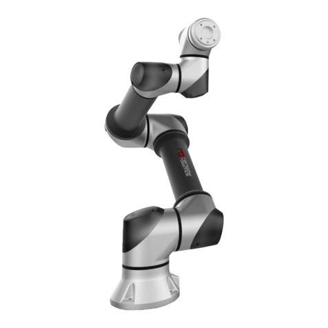
ELITE ROBOT EC Series User manual

ELITE ROBOT EC Series
Maintenance Manual
EC612 Service Manual
ELITE ROBOT Co.,Ltd
2021-02-04
Version: 5.0.28
www.elibot.cn

Contents
1 Disassembly joint 1
1.1 Robotarmconguration ................................ 1
1.2 Brakerelease ...................................... 2
1.3 General guidance to separate joint from counterpart . . . . . . . . . . . . . . . . . . 2
1.4 Torquevalues ...................................... 6
1.5 Base joint-Base mounting bracket . . . . . . . . . . . . . . . . . . . . . . . . . . . 7
1.6 ShoulderJoint-Basejoint................................ 8
1.7 Upperarm-Shoulderjoint................................ 9
1.8 Elbowjoint-Upperarm ................................. 11
1.9 Elbow counterpart-Elbow joint . . . . . . . . . . . . . . . . . . . . . . . . . . . . . 13
1.10Wrist1joint-Lowerarm ................................ 14
1.11 Wrist 2 joint-Wrist 1 joint . . . . . . . . . . . . . . . . . . . . . . . . . . . . . . . . 15
1.12 Wrist 3 joint-Wrist 2 joint . . . . . . . . . . . . . . . . . . . . . . . . . . . . . . . . 16
1.13Toolange-Wrist3joint ................................ 16
2 Alarm description 18
2.1 Robotprogramalarm.................................. 18
2.2 Servodrivealarm.................................... 39

Chapter 1 Disassembly joint
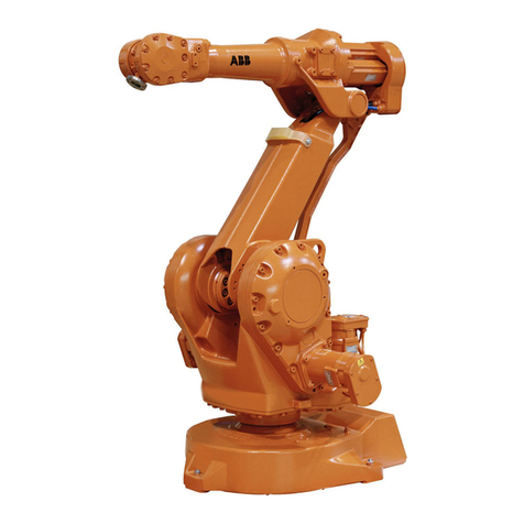
1.1 Robot arm conguration
Section 1.13 Tool ange-Wrist 3 joint
Section 1.12 Wrist 3 joint-Wrist 2 joint
Section 1.11 Wrist 2 joint-Wrist 1 joint
Section 1.10 Wrist 1 joint-Lower arm
Section 1.9 Elbow counterpart-Elbow joint
Section 1.8 Elbow joint-Upper arm
Section 1.7 Upper arm-Shoulder joint
Section 1.6 Shoulder Joint-Base joint
Section 1.5 Base joint-Base mounting bracket

1.2 Brake release
1.2 Brake release
If required, you can release the brake without power.
CAUTION
1. Before releasing the brake, you should not dismount any dangerous parts in
case of hazardous situations.
2. Proper mechanical support should be provided when releasing the brake on
Base, Shoulder or Elbow joint.
3. Make sure there is no danger to personnel when the brake is released.
4. Please move the joint in its proper range. (Do not exceed 160 degrees to
enable the robot nding its original physical position)
Steps
1. Shut down the controller.
2. Gently remove the decorative ring by using tweezers or screwdriver. Be careful not to scratch
the surface of the cap.
3. Remove the joint cap.
4. Push the brake down and then rotate the joint, as shown in Figure 1-1 .
Figure 1-1 : Pushing the brake down
5. Put the cap onto the joint, fasten screws with 0.4Nm and then attach the decorative ring.
6. Turning on the controller.
1.3 General guidance to separate joint from counterpart
Disassemble
1. Please fully understand the manual before disassemble the robot, and prepare necessary tools.
2. Move the robot to a comfortable position for disassembly or dismount the entire manipulator
and place it on a solid surface.
3. Shut down the controller.
4. Gently remove the decorative ring by using tweezers or screwdriver.
5. Remove the joint cap.
2DN:T202001003

1.3 General guidance to separate joint from counterpart
6. Gently unplug the cable connector. Do not damage the PCB, as shown in Figure 1-2 .
Figure 1-2 : Unplug the cable connector
7. Disconnect wires.
8. Remove the alignment screw, as shown in Figure 1-3 .
Figure 1-3 : Removing the alignment screw
9. As shown below, gently remove the rubber ring by using tweezers or screwdriver and wrap it
around the cap.
10. Slide the white transition ring back. 10 screws are visible (5 on each side of joint), loosen the
screws with an open-ended spanner for 720 degrees approximately.
11. Pull the two parts apart and gently twist them clockwise 10 degrees approximately until a me-
chanical stop is met, then they can be separated completely, as shown in Figure 1-4 .
3DN:T202001003

1.3 General guidance to separate joint from counterpart
Figure 1-4 : Separating the joint
Assemble:
After replacing the joint, assemble the robot arm as follows.
1. Insert eight screws into the joint cap and twist them for 720 degrees approximately. Make sure
the heads of the bolt are ush, as shown in Figure 1-5 .
Figure 1-5 : Inserting the screws
2. Gently insert the keyhole-type of the tool ange into bolts. The alignment pin should be xed
correctly.
3. Gently twist the joint clockwise 10 degrees until a mechanical stop is met.
4. Gently tighten the screws, until they are almost in the correct position then tighten in cross order.
(as shown in Figure 1-6 ).
Start with the screws next to the alignment pin and tighten with the correct torque.
See Section 1.4.
Figure 1-6 : tightening the screws in cross order.
4DN:T202001003

1.3 General guidance to separate joint from counterpart
5. Slide the transition ring into place and gently put the rubber ring back on the top of the transition
ring, as shown in Figure 1-7 .
Figure 1-7 : Sliding the ring
6. Mounting the alignment screws and tighten with 0.4Nm.
7. Twist the communication cable 540 to 720 degrees before connecting which can reduce the noise
in the electrical system, as shown in Figure 1-8 .
Figure 1-8 : Twisting the communication cable
8. After installing the joint caps, make sure that the following switches are at correct order.
Figure 1-9 : Base joint Figure 1-10 : Shoulder joint Figure 1-11 : Elbow joint
5DN:T202001003

1.4 Torque values
Figure 1-12 : Wrist 1 joint Figure 1-13 : Wrist 2 joint Figure 1-14 : Wrist 3 joint
9. Install the joint cap and tighten with 0.4Nm and then attach the decorative ring.
1.4 Torque values
EC612 Torque values:
CONNECTION TORQUE HEAD SIZE
Base mounting bracket-Base 9Nm 8mm
J1 Base-J2 Shoulder 9Nm 8mm
J2 Shoulder-Upper arm 9Nm Hex key4
Upper arm ange-Upper arm 9Nm 8mm
Upper arm-J3 Elbow 4Nm 7mm
J3 Elbow-Elbow counterpart 4Nm 7mm
Elbow counterpart-Lower arm ange 4Nm Hex key3
Lower arm ange -Lower arm 2Nm 5.5mm
Lower arm-J4 Wrist 1 2Nm Hex key2.5
J4 Wrist 1-J5 Wrist 2 2Nm 5.5mm
J5 Wrist 2-J6 Wrist 3 2Nm 5.5mm
J6 Wrist 3-Tool ange 2Nm 5.5mm
Joint cap 0.4Nm Torx T10
Attention: Check the torque wrench again before using to ensure the correct alignment
torque.
6DN:T202001003

1.5 Base joint-Base mounting bracket
Figure 1-15 : Torque values
1.5 Base joint-Base mounting bracket
Disassemble
For details and photos please see Section 1.3.
1. Shut down the controller.
2. Gently remove the rubber ring by using tweezers or screwdriver and wrap it around the cap.
3. Slide the white transition ring back. 10 screws are visible (5 on each side of joint), loosen the
screws with an 8mm open-ended spanner for 3.5 turns approximately.
4. Pull the base joint and the base mounting bracket apart and then twist the base joint clockwise
10 degrees approximately until a mechanical stop is met.
5. Pull the base joint away from the base mounting bracket.
6. Disconnect wires between base joint and base mounting bracket.
2 brown wire 48VDC
2 black wire GND
1 twisted pair 485 communication
Assemble
For details and photos please see Section 1.3.
1. As shown in Figure 1-16 , replace the base plate and reconnect wires.
7DN:T202001003

1.6 Shoulder Joint-Base joint
Figure 1-16 : Replacing the base plate
2. Twist the communication cable 540 to 720 degrees before connecting which can reduce the noise
in the electrical system.
3. Insert the screws into the base mounting bracket and twist them for 900 degrees approximately.
Make sure the heads of the bolt are ush.
4. Align the key hole with the screw and gently insert the base joint into the base mounting bracket.
Gently twist the base joint counter-clockwise until a mechanical stop is met.
5. Gently tighten the 10 screws and then tighten in cross order with 9Nm.
6. Slide the white transition ring into place and gently put the rubber ring onto the top of the
transition ring.
1.6 Shoulder Joint-Base joint
Disassemble
For details and photos please see Section 1.3.
1. Shun down the controller.
2. Remove the decorative ring and disassemble the cap.
3. Disconnect wires between base joint and shoulder joint.
2 brown wire 48VDC
2 black wire GND
1 twisted pair 485 communication
4. Gently remove the rubber ring by using tweezers or screwdriver and wrap it around the cap.
5. 5.Slide the white transition ring back. 10 screws are visible (5 on each side of joint), loosen the
screws with an 8mm open-ended spanner for 3.5 turns approximately.
6. Twist the shoulder joint clockwise 10 degrees approximately until a mechanical stop is met.
7. Gently pull away the base joint from shoulder joint.
Assemble
For details and photos please see Section 1.3.
8DN:T202001003

1.7 Upper arm-Shoulder joint
1. Insert the screws into the base joint and twist them for 3.5 turns. Make sure the heads of the bolt
are ush.
2. Align the key hole with the screw and gently insert the shoulder joint into the base joint. Gently
twist the base joint counter-clockwise until the mechanical stop is met.
3. Tighten the 10 screws lightly and then tighten in cross order with 9Nm.
4. Slide the white transition ring into place and gently put the rubber ring onto the top of the
transition ring.
5. Mount the alignment screw and tighten with 0.4Nm.
6. Reconnect wires as shown in Figure 1-17 .
Figure 1-17 : Reconnecting wires
7. Twist the communication cable 540 to 720 degrees before connecting which can reduce the noise
in the electrical system.
8. 7.Mount the cap on base joint, tighten with 0.4Nm and then attach the decorative ring.
1.7 Upper arm-Shoulder joint
Disassemble:
For details and photos please see Section 1.3.
1. Shut down the controller.
2. Remove the decorative ring on the shoulder joint by using screwdriver or tweezers.
3. Remove the cap.
4. Disconnect wires between the upper arm and the shoulder joint.
1 brown wire 48VDC
1 black wire GND
1 twisted pair 485 communication
5. As shown below, remove the rubber ring by using screwdriver and then wrap it around the
cylinder.
9DN:T202001003

1.7 Upper arm-Shoulder joint
6. As shown below, remove the supporting ring. 12 screws are visible, loosen M5 screws with an
8mm open-ended spanner.
7. Remove the cylinder from the shoulder joint.
8. You can also remove 10 M5 hex screws on the connecting ange by using Hex key4.
Assemble:
For details and photos please see Section 1.3.
1. Make sure that the shoulder joint has connected with the upper arm ange or you should connect
them by twisting M5 screws with 9Nm.
2. Insert the upper arm ange into the cylinder, x the threaded hole of the cylinder and the hole
of the upper arm ange.
3. Tighten all screws lightly and then tighten with 9Nm.
4. Connect wires correctly as shown in Figure 1-18 .
10 DN:T202001003

1.8 Elbow joint-Upper arm
Figure 1-18 : Conectting wires
5. 5.Twist the communication cable 540 to 720 degrees before connecting which can reduce the
noise in the electrical system.
6. Mount the white cap on the shoulder joint and tighten with 0.4Nm
7. Install the decorative ring onto the cap.
8. Install the supporting ring onto the upper arm ange and then put the rubber ring on the sup-
porting ring.
1.8 Elbow joint-Upper arm
Disassemble:
1. Shut down the controller.
2. Separate the upper arm and the shoulder joint before separating the elbow joint from the upper
arm, consult Section 1.7.
3. After separating the upper arm and the shoulder joint, remove the cap of the elbow joint and
then disconnect wires between the upper arm and the elbow joint.
1 brown wire 48VDC
1 black wire GND
1 twisted pair 485 communication
4. As shown below, insert the Hex key3 with long rod into the cylinder and remove 10 M4 Hex
screws which connect the elbow joint and the upper arm.
11 DN:T202001003

1.9 Elbow counterpart-Elbow joint
5. Pull the elbow joint away from the upper arm.
Assemble:
1. As shown below, gently insert the cylinder into the elbow joint, take care of the alignment hole
and pass wires through the wire hole.
2. Insert the Hex key3 with long rod into the cylinder and remove 10 M4 Hex screws with 4Nm
which connect the elbow joint and the upper arm.
3. Connect wires between the upper arm and the elbow joint as shown in Figure 1-19 .
Figure 1-19 : Connecting wires
4. Install the elbow joint cap with 0.4Nm and then attach the decorative ring.
5. Assemble the shoulder joint and the upper arm, consult chapter Section 1.7.
12 DN:T202001003

1.9 Elbow counterpart-Elbow joint
1.9 Elbow counterpart-Elbow joint
Disassemble
For details and photos please see Section 1.3.
1. Shut down the controller.
2. Remove the decorative ring by using screwdriver or tweezers and then remove the joint cap.
3. Disconnect wires between the elbow joint and the lower arm.
1 brown wire 48VDC
1 black wire GND
1 twisted pair 485 communication
4. Remove the rubber ring by using screwdriver or tweezers and wrap it around the cap.
5. Slide the white transition ring back. 10 screws are visible (5 on each side of joint), loosen the
screws with a 7mm open-ended spanner for 900 degrees approximately.
6. Twist the elbow counterpart counter-clockwise 10 degrees approximately until a mechanical
stop is met.
7. Pull away the elbow joint from the elbow counterpart.
Assemble
For details and photos please see Section 1.3.
1. Insert the screws into the elbow counterpart and twist them for 900 degrees approximately. Make
sure the heads of the bolt are ush.
2. Remove the decorative ring by using screwdriver or tweezers and then remove the joint cap.
3. Pass the lower arm cable through the ange shaft of the elbow joint and align the screws of the
elbow mating joint with the key hole of the elbow joint ange shaft and gently insert, then twist
counter-clockwise 10 degrees until a mechanical stop is met.
4. Tighten the 10 screws lightly and then tighten in cross order with 4Nm.
5. Slide the white transition ring in place and gently put the rubber ring back to the top of the
transition ring.
6. Mount the alignment screw with 0.4Nm.
7. As shown in Figure 1-20 , Connect wires of elbow joint and the lower arm.
13 DN:T202001003

1.10 Wrist 1 joint-Lower arm
Figure 1-20 : Connecting wires of elbow joint and the lower arm
8. Twist the communication cable 540 to 720 degrees before connecting which can reduce the noise
in the electrical system.
9. Install the elbow joint cap with 0.4Nm and attach the ring.
1.10 Wrist 1 joint-Lower arm
Disassemble
For details and photos please see Section 1.3.
1. Shut down the controller.
2. Remove the decorative ring and then remove the wrist joint cap.
3. Disconnect wires between the lower arm and the wrist 1 joint.
1 brown wire 48VDC
1 black wire GND
1 twisted pair 485 communication
4. Separate the elbow counterpart and the lower part, consult Section 1.7.
5. Separate the wrist 1 joint and the lower part, consult Section 1.8.
6. Pull away the wrist 1 joint.
Assemble
For details and photos please see Section 1.3.
1. Gently insert the wrist 1 joint with screws into the lower arm.
2. Tighten 8 M3 Hex screws lightly by using Hex key2.5 with long rod and then tighten in cross
order with 2Nm.
3. Connect wires between the lower arm and the wrist 1 joint as shown in Figure 1-21 .
14 DN:T202001003

1.11 Wrist 2 joint-Wrist 1 joint
Figure 1-21 : Connect the wires
4. 4.Install the wrist 1 joint cap with 0.4 Nm and attach the decorative ring.
5. Assemble the elbow joint and the lower arm, consult Section 1.7.
1.11 Wrist 2 joint-Wrist 1 joint
Disassemble
For details and photos please see Section 1.3.
1. Shut down the controller.
2. 2.Remove the wrist 2 joint cap and the decorative ring.
3. Disconnect wires between the wrist 1 joint and the wrist 2 joint.
1 brown wire 48VDC
1 black wire GND
1 twisted pair 485 communication
4. Gently remove the gray rubber ring and wrap it around the wrist 1 joint, then slide the white
transition ring back to the wrist 1 joint.
5. 8 screws are visible (4 on each side of joint), loosen the screws with a 5.5mm open-ended spanner
for 4.5 turns approximately.
6. Pull the wrist 1 joint and wrist 2 joint apart, twist the wrist 2 joint counter-clockwise 10 degrees
until a mechanical stop is met.
7. Pull away the wrist 1 joint from wrist 2 joint.
Assemble
For details and photos please see Section 1.3.
1. Insert eight screws into the Wrist 2 joint and twist them for 4.5 turns. Make sure the heads of
the bolt are ush.
2. Gently insert wrist 2 joint with screws into the wrist 1 joint and then twist clockwise for about
10 degrees until a mechanical stop is met, make sure that wires are connected through the wire
hole of the wrist 2 joint correctly.
3. Tighten the 8 screws lightly and then tighten in cross order with 2Nm.
15 DN:T202001003

1.12 Wrist 3 joint-Wrist 2 joint
4. Slide the white transition ring to the wrist 2 joint and then put the gray rubber ring to the top of
the transition ring.
5. Connect wires as shown in Figure 1-22 , twist the communication cable 540 to 720 degrees
before connecting which can reduce the noise in the electrical system.
Figure 1-22 : Connecting wires
6. Install the wrist 2 joint cap with 0.4Nm and then attach the decorative ring.
1.12 Wrist 3 joint-Wrist 2 joint
Disassemble & Assemble:
Procedure for separating the wrist 3 joint from wrist 2 joint is similar to separation of the upper
arm and the shoulder joint, consult Section 1.11.
1.13 Tool ange-Wrist 3 joint
Disassemble
For details and photos please see Section 1.3.
1. Shut down the controller.
2. Gently remove the gray rubber ring by using screwdriver or tweezers and wrap it around the
wrist 3 joint, then slide the white transition ring back to the wrist 3 joint.
3. 8 screws are visible (4 on each side of joint), loosen the screws with a 5.5mm open-ended spanner
for 4.5 turns.
4. Pull the wrist 3 joint and tool ange apart, twist the tool ange counter-clockwise 10 degrees
approximately until a mechanical stop is met.
5. Gently pull the tool ange a bit from the wrist 3 joint. Excessive force may damage PCD.
6. Disconnect wires between the tool ange and the wrist 3 joint.
1 brown wire 48VDC
1 black wire GND
1 twisted pair 485 communication
16 DN:T202001003

1.13 Tool ange-Wrist 3 joint
7. Pull away the tool ange from wrist 3 joint entirely.
Assemble
For details and photos please see Section 1.3.
1. Insert the screws into the tool anges and then twist for 4.5 turns. Make sure the heads of the
bolt are ush.
2. Connect wires between the wrist 3 joint and tool ange as shown in Figure 1-23 .
Figure 1-23 : Connecting wires between the wrist 3 joint and tool ange
3. Gently insert the tool ange into the wrist 3 joint. Make sure the heads of the bolt are inserted
into the keyhole-type correctly.
4. Tighten the screws lightly and then tighten in cross order with 2Nm.
5. Slide the white transition ring in place and gently put the rubber ring back to the top of the
transition ring.
17 DN:T202001003

Chapter 2 Alarm description
2.1 Robot program alarm
Alarm number Description
0-2000-nline Unsupport IO type %s
0-2000-nline Error type
0-2000-nline TIMER instruction decoding error
0-2000-nline PULSE instruction decoding error
0-2000-nline PULSE instruction decoding error
0-2000-nline AOUT analyze variable %s
0-2000-nline Analog input decoding error
0-2000-nline AIN analyze variable %s
0-2000-nline RESTARTLUA Analyze index error
0-2000-nline STOPLUA must set INDEX num
0-2000-nline %s analyze VJ=
0-2000-nline RESTARTLUA range error.
0-2000-nline setmlle run error.
0-2000-nline TIMER instruction decoding error
0-2000-nline CLEAR instruction decoding error
0-2000-nline CLEAR must give const number
0-2000-nline CLEAR instructions unsuppoted types
0-2000-nline %s analyze data
0-2000-nline %s av analyze variable
0-2000-nline %s ac analyze variable
0-2000-nline %s dist analyze variable
0-2000-nline %s Wvon no para WEV
0-2000-nline HSEN Instruction Parameter T Decoding Error
This manual suits for next models
1
Table of contents
