Elite 4'3" wide compact User manual


PARTS LIST
4 X 4 6 X 4 8 X 4 10 X 4
1Nuts and bolts M6 90 100 110 124
2Wire clips 174 214 254 298
3Overlap clips 26 32 38 44
4Casement stay 1112
5Stay pins 2224
6Pins, nuts and bolts M4 66612
7Double door lock 1111
8Self tapping screw 28 28 28 28
9Glazing beading—meters 49 58 68 77
10 Door skids 2222
11 Eaves plates Taped together with one
casement stay
4444
12 Ridge plates 2222
13 Door wheels and fittings 4444
14 Ridge 1111
15 Combined gutter/eave 2222
16 Built in base side 2222
17 Side bracing angle 2224
18 Door end built in base 2222
19 Top door track 1111
20 Top door panel With name plate taped
together and marked
door
2222
21 Bottom door panel 2222
22 Middle door panel 6666
23 Door track support 1111
24 Door posts (2 unhanded 2 handed) 4444
25 Side glazing bar 2468
26 Roof glazing bar 2468
27 Vent (in packs) 1112
28 Door end glazing bars Taped together and
marked door end
2222
29 Door end horizontal angle 2222
30 Door end bracing angle 2222
31 Door track support flat bar 2222
32 Rear end built in base 1111
33 Rear end glazing bars Taped together and
marked rear end
2222
34 Rear end horizontal angle 1111
35 Rear end bracing angle 2222
36 Corner bars in two packs 8888
37 Glass (see glazing plan in back of booklet)
37 Door draught excludes 2222
38 Corner brackets 4444
40 Angle brackets 6810 12

HELPFUL HINTS
Please do take your time and be sure to read all instructions carefully before assembling.
Consider purchasing the Elite Installation tool kit – see accessory brochure for contents of kit.
Do not assemble frame in high winds.
The greenhouse frame should be anchored to a permanent foundation. This will not only help secure
it against powerful winds but will help prevent breakage of the glass caused by the freezing and
thawing process of the earth.
When building your own brick/concrete foundations ensure that they are level and square otherwise
your frame will not be correct and the glass will not fit.
Be sure all four corners of the constructed greenhouse are square before installing glass, and do not
install the glass till the greenhouse is on a permanent foundation.
Do not place your greenhouse in vulnerable locations such as under trees, playing areas, etc.
Children should not play near glass greenhouses.
REMEMBER: glass is fragile, handle with care!
Protective eye glasses should be worn.
Gloves should be worn.
If your greenhouse is a painted one there are a few 1/8” (3mm) holes in the end of the bars. These
are jig holes for painting and have no bearing on construction. (Key Point).
WHEN CONSTRUCTING A POWDER COATED MODEL PLEASE TAKE CARE NOT
TO DAMAGE THE FINISH BY WORKING ON CONCRETE OR PATIOS. Take great care
in opening the polythene packages. Do not run a knife down the side of the packs as this may
scratch the paintwork.
N.B. This plan covers the entire Compact range. The only difference between a 4ft long and a
10ft long for example are a few extra pieces of alloy, glass, nuts and bolts etc. The construc-
tion of the sub-frame assemblies are the same but for the purposes of this booklet we have
used the 4 x 4 model as the benchmark. Therefore only one plan is needed.
We reserve the right to alter and improve our products.

INSTALLATION INSTRUCTIONS FOR THE 4’3” WIDE MODEL
“COMPACT RANGE”
The contents of this carton are divided into the different frame assemblies that collectively
make up the completed greenhouse framework.
It is recommended that each framework assembly is fully completed before moving onto the next.
The contents are as follows:
1. Two side frames
2. Rear end frame
3. Door end frame
4. Roof vent
5. Doors
6. Bag of fittings containing:
Nuts and bolts general assembly
Overlap clips for glass
Spring clips for glass
Casement stay
Casement stay nuts and bolts
Four eave plates (not in the main bag, but taped up with the casement stay)
Two ridge plates
Four door wheels
Two door guides
Small self tapping screws
Double door lock
Rectangular plates (3 elongated holes)
7. Roof bars
8. Coil of glazing beading
9. One length of ridge
10. Two draught excluders
For clear identification of parts and the number required please carefully refer to he earlier
pages of component drawings and parts list.

SIDE FRAME ASSEMBLY
Components
1 Combined gutter/eave bar
1 Built in base
Glazing bars—1 if 4’ long Bracing angle 1 if 4’ or 6’ long
2 if 6’ long 2 if 8’, 10’ or 12’ long
3 if 8’ long
4 if 10’ long
5 if 12’ long
From the fitting list you will require nuts and bolts and glazing beading.
STARTING with the side frame.
With a built in base model the base is an integral part of each frame and
is therefor not built as a separate entity.
Slide the glazing beading into each side bar taking care not to stretch the material. Trim off any sur-
plus, level with the ends of the glazing bar.
Lay out the pieces on the ground as though you were standing inside the house i.e. with the gutter
and built in base facing downwards and the bolt channel of the glazing bars upwards. (Key Point)
Slide a bolt into each end of each glazing bar into the bolt slot on the back of the bar. If you have
bought a shelf to go in your greenhouse and you intend to fit it on a side wall, use the ½” headed
bolts provided with the shelf fittings.
Fix the combined eaves bar and gutter to the glazing bars pushing the bolts through the holes in the
eaves bar and securing with a nut. You do not need to tighten the nuts too much at this stage, but
they need to be tight enough to stop the bolts slipping out of the glazing bar.
Fix the built in base to the middle glazing bar by pushing the bolt through the hole in the built in
base and tightening as before. (4’ long model will only have 1 side glazing bar per side assembly, 2
for the 6’ etc.).
Correctly position the built in base on the outermost glazing bars by pushing the bolts through the
holes in the built in base, but do not put the nuts on yet. (6’, 8’ and 10’ models only).
Place the side bracing angle over these bolts so that they point outwards towards the ends of the
eaves bar. They must be arranged so that the flat bit of the angle in each case faces towards the mid-
dle of the house (i.e. elongated hole will be by the eaves in one case and by the built in base in the
other. (Key Point). 4’ and 6’ long model will have 1 side bracing angle per side. This is to attach to
the top of the 1st glazing bar and then will attach to the gable end during general assembly, at the
base.
Put nuts on the bottom bolts and lightly tighten.
Do the same with the other side frame assembly.
Make sure that the glazing bars touch both the built in bases and the combined eaves gutter bar in
each case. Tighten all nuts.
If you are fitting your greenhouse onto hard standing (flags, concrete etc), then insert bolts into the
bolt channel of the built in base (generally 1 every 2’). These will be used to anchor the greenhouse
to the floor during general assembly. Do not insert these bolts if you intend to install your green-
house on to soft ground.

BEWARE OF SHARP EDGES!

REAR END ASSEMBLY
N.B. The roof corner bars are marked “R” on the outside, which indicate that they meet at the
ridge and are also mitred at both ends. If you have a painted greenhouse there is no letter “R” on
the corner bar. You must ensure that the “middle” hole is nearer to the eaves plate than the
ridge plate. (Key Point).

From the main bag of fittings you will require the nuts and bolts, two eave plates and one ridge
plate. These are packed with the casement stay and are separated from the main bag of fittings.
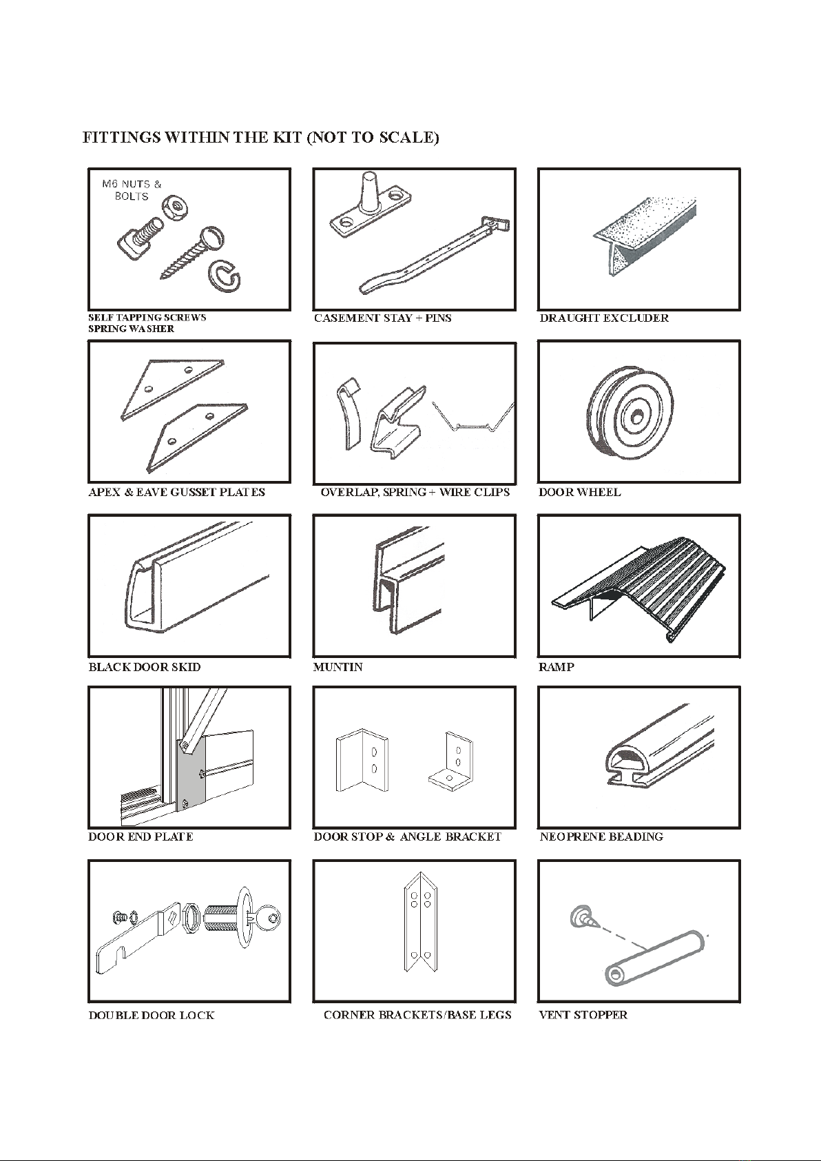
Components:
1 alloy built in base
2 glazing bars
2 rear end bracing angles
1 rear end horizontal angle
2 roof corner bars (marked “R” at the apex)
2 side corner bars (unmarked)
Corner bars are in two packs of 4 and are identical for both gables. They are marked “corner
bars”.
INSTRUCTIONS
1. Slide the glazing beading into each glazing bar and corner bar taking care not to stretch the
material. Trim off any surplus level with the ends of the glazing bar. The corner bars have 3 grooves
to receive beading. Do not use the middle one, only the two outer grooves require beading.
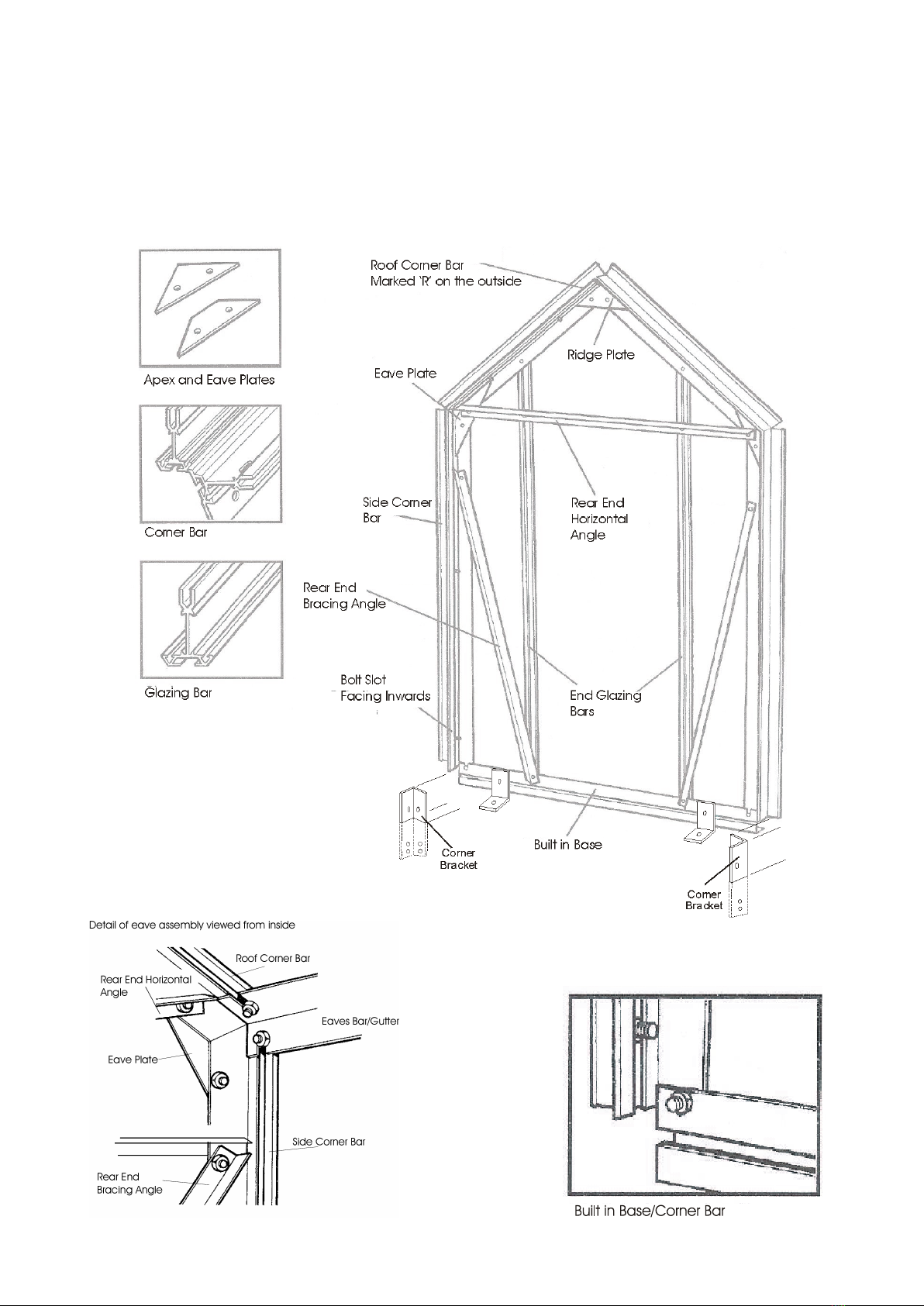
2. Lay out the frame as though you were standing on the inside i.e. with the bolt slot uppermost,
roof corners marked “R” at the apex, opposite each other, facing downwards (i.e. “R” on outside).
The roof corner bars are mitred at both ends where as side corner bars are mitred at one end only
(Key Point). The bolt slot is on the inside and faces inwards during initial construction. If you have
a painted greenhouse there is no letter “R” on the corner bar. You must ensure that the “middle”
hole is nearer to the eave plate than the ridge plates. (Key Point).
3. Slide two bolts into the bolt channel of each corner bar, put a nut on and finger tip tighten ap-
prox. 3” from the end of the bar. These will later be used in the general assembly for fixing the
ridge, eave and built in base to the ends. Now secure the ridge plate and eaves plates by inserting
bolts through the ‘plates’ and into the holes punched in the flange of the corner bar, at the apex and
eave. Do not tighten the nuts and bolts in the plates at this stage, finger tip tighten is sufficient.
N.B. If you have the 4’ option the roof vent slam bar will attach to one of the corner bars. You will
need to insert an extra bolt into the bolt slot of the roof corner bar onto which the vent will close.
4. Attach the built in base to the side corner bars by inserting a bolt through the hole in the
flange of the corner bar and into the slot in the built in base.
5. Attach the vertical glazing bars to the built in base by inserting a bolt into the bolt channel of
the glazing bars and locating it with the punched holes in the built in base. Before securing the nuts
attach the rear end bracing angle which goes diagonally from the spare hole in the corner bar near to
the eave plate down to the built in base to the same bolt as illustrated. The top of the diagonal angle
tie now attaches to the pre-fabricated holes approx. 8” from the top of the side corner bar.
6. Slide two bolts into the bolt channel at the top of the two vertical glazing bars and secure the
second one to the roof corner bars by inserting the bolt through the punched hole in the flange.
7. You can now attach the rear end horizontal angle to the top bolt of the eave plate and to the
other bolts in the glazing bars you inserted in 6, above.

8. Check that all angles between built in base and the vertical members are at right angles and
that the glazing bars are right into the built in base at the bottom. (Key Point).
9. Tighten all nuts.
10. Slide two extra bolts into the built in base. This will be used later to attach the corner bracket.
11. Slide a bolt into the bolt slot in the built in base section, one at each end. Attach the corner
bracket so that it is pointing downwards. If you are fitting your greenhouse onto soft ground, then
do not fit the corner bracket yet. If you are on a patio, you will need to cut the bracket off, level
with the bottom of the built in base and slide extra bolts into the bolt channel to be attached to the
corner bracket (generally 1 every 2’). If you are on soil, the corner bracket will go into the ground at
general assembly.
DOOR END ASSEMBLY
From the main bag of fittings you will require the nuts and bolts, 2 eave plates and 1 ridge plate.
These are packed with the casement stay and are separate from the main bag of fittings.
Please note, you only require approx. 40mm of beading in the inside ‘v’ groove of the end glazing
bars.
Components
2 door end built in base
2 end glazing bars
side corner bars (unmarked)
top door track
door end horizontal angle
door end bracing angles
main door track support
2roof corner bars (marked “R”)
INSTRUCTIONS
1. Assemble the frame in exactly the same way as the rear
end, up to and including stage 3 of the rear end. The differ-
ence with the door end is that instead of 1 long built in base
piece, the door end has 2 smaller pieces (1 either side of the
door opening) and 1 door end cill. The 2 vertical glazing bars
are longer than the same bars used on the rear end assembly
(Key Point).
2. Now engage the door end cill with the 2 built in base pieces by push-
ing the angle of the cill under the locator as shown in the diagram. At this
stage the cill will move freely left and right but will remain located to the
built in base.
3. Slide 2 bolts into the bottom of each glazing bar and 3 bolts (only 1 if
greenhouse to be sited on soft ground) into the free end of each built in base
section. Attach the 2nd bolt in the glazing bar to the hole in the door end cill,
but do not put a nut on yet. Remember, the door end glazing bars are 95
mm longer than the rear end ones and do not sit on top of the base (as
the rear end glazing bars do), they go down the side of the base and attached to the bottom
cill. (Key Point).

4. Attach the rectangular plate (with 3 elongated holes) to the 2 bolts inserted in the glazing bars
and the last bolt inserted into the built in base ensuring that the glazing bar is tight down into the
angle of the door end cill. Attach the diagonal angle to the top bolt of the rectangular plate. The 2
unoccupied bolts in the built in base sections will be used to anchor the greenhouse to the floor.
5. Attach the main door track support (shaped like a letter
‘Z’ to be found with the door panels) to the two bolts that secure
the glazing bars to the corner bars. (Key Point). This ‘Z’ shaped
bar must be fitted with the two outside slots facing upwards (as
illustrated) not downwards. The main door track support attach-
es to the upper bolt by going between the corner bar flange and
the glazing bar. (Key Point).
6. The two door end horizontal angles attach to the top bolt
in the gusset plate and the vertical glazing bars.
7. Stand the frame up and bolt the door track to the main door track support and the small angle
door track support by inserting 3 bolts into the bolt slot of the door track. Position 3 of these
through the 3 holes in the door track support above the door opening. At this stage you do not need
to adjust the track for level or square. This will be done later when fitting the doors.
8. Insert 2 extra bolts into each end of the door track which will be used later during general as-
sembly.
9. When this has been achieved tighten all nuts.
10. Slide a bolt into the bolt slot in the built in base section, one at each end. Attach the corner
bracket so that it is pointing downwards. If you are fitting your greenhouse onto soft ground, then
do not fit the corner bracket yet. If you are on a patio, you will need to cut the corner bracket off
level with the bottom of the built in base and slide extra bolts into the bolt channel to which will be
attached the anchor brackets (generally 1 every 2’). If you are on soil, the corner bracket will go in-
to the ground at general assembly.
N.B. Please note carefully the correct position of the main door support. The slotted holes at either
end are facing skywards NOT downwards. (Key Point).

DOOR END ASSEMBLY

DOOR FRAME ASSEMBLY
Each Door consists of:
1 unhanded door post
1 handed door post (handed post for left door is different profile to the handed right hand door post)
3 infill panels (1 with pre fabricated lock hole) for lock barrel
1 top and bottom door panels
3 panels of glass which must be fitted during door assembly. It is not possible to fit glass after the
door is built
From the main bag of fittings you require;
2 door wheels
1 clip on nylon door skid (this might already be fitted to the bottom door panel)
2 lengths of black brush draught excluder with PVC carrier
Door lock, self tapping screws and spring washers
12’ glazing beading
Door handles
3 PVC Glass strips
Left hand Door (viewed from outside)
Identify the correct door posts. The handed door post for the left hand door has a bolt channel,
whereas the handed door post for the right hand door post does not. (Key point).
1. Place one unhanded post and the handed post for left hand door on a level surface roughly two
feet apart with the bolt slots facing downwards. (Unhanded door post on
the left, handed door post on the right). The top of each side post has two
screw holes in it, the bottom has three. (Key point). Slide the glazing
beading into the groove of each bar i.e. only one length of glazing bead-
ing per bar.
2. Place the top, bottom and 3 infill panels in position as shown by the po-
sition of the screw holes in the side pieces and the panels. The top panel has the greenhouse
name on it. The bottom panel has the edge for the door skid to fit on. The lower infill panel
locks on to the bottom panel. The infill panel for the left hand door does not have a pre fabri-
cated hole for the lock barrel.
3. Fix the left hand door post to the door panels by screwing through the door side pieces into
the holes provided in the edge of the panels with the self tapping screws. The screws will go
in more easily and with out danger of trying to go crooked if you can put a small amount of
grease on the screw before assembling the doors. Alternatively, you could insert the screws
into the screw eyes of the door panels before assembling the door; this would have the effect
of pre-self tapping the panels prior to assembly, making assembly easier.
4. GLASS MUST BE FITTED TO EACH DOOR BEFORE THE 2ND DOOR POST IS
FITTED—KEY POINT

5. Before fitting the unhanded door post, offer the glass panels to the door (see glazing plan in
booklet for glass size guide on door), slide them in from the side. Carefully attach the unhand-
ed door post in the same way as before, ensuring the glass is sitting in the correct position
(sitting on the beading channels of the door posts) before tightening the screws.
6. Make sure all angles are square
and tighten all screws. Now insert
2 glazing clips to the glass on the
unhanded door post.
The other side of the door is
clipped using a pvc glass strip (or
clip cap). Cut the strip to the correct length and push into the cavity between the glass and the
handed door post. The cap when fitted acts as a wedge to prevent movement of the glass. Met-
al clips are not fitted to this bar.
7. Fix each door wheel into position by pushing the bolt provided through the centre of the
wheel and then through the hole in the top door panel from underneath (i.e. from the inside of
the door). Put the washer over the bolt and secure with the nut provided, tightening until there
is no movement on the bolt. The nuts are lock-nuts and are harder to put on than normal nuts
in general assembly. The wheel will revolve freely because it has ball bearings in it. The
wheel has a collar protruding from the centre, this collar goes against the inside face of
the top door panel. (See picture below).
8. Slip the nylon door skids on each of the bottom panels. This may already have been done pri
or to delivery. After fitting the doors (see later in the booklet), you may need to lower the
door skid so that it engages with the bottom door cill to allow smooth movement of the door.
Lower the skid on each door and insert a self tapping screw at each end of the skid to rein
force the position.
9. Build the right hand door using the remaining handed and unhanded door post. Viewed from
the outside, the handed door post will be on the left of the door, while the unhanded door post
will be on the right. At this point you must decide the height you would like your door lock.
The hole to take the door lock is on the left hand side of the infill panel. You can decide to fit
this panel to the 2nd or 3rd panel down. Make sure you fit the glass before final fixing of
the door. See glazing plan towards the back of this booklet
10. Thread the stainless steel backed brush
extruder into the PVC carrier. This may
already have been done prior to delivery
11. Turn the doors over and insert the black
brush draught excluder in the groove (bolt
slot) in the unhanded door posts. Insert a
nut and bolt at the bottom of each un-
handed door post and tighten so that the
brush will not slip down when the door is
in its upright position, Cut off the surplus
brush and carrier at the top of the bar
12. Do not fit the door to the gable at this
stage – wait until the structure is fully
assembled prior to glazing.
13. Door handles can now be fitted.


FITTING THE DOOR HANDLES
The handles are fitted to the infill panel on each door (choose between 1st or 2nd panel down). Po-
sition the handle centrally, and mark the hole position. Drill 7mm diameter holes (2 holes per door),
then fit the handles, and secure with a nut and bolt.
FITTING THE DOOR LOCK
The door lock must be fitted after the doors are in posi-
tion (Key Point). Undo the ring bolt from the door lock,
and insert the barrel through the hole in the panel from
the outside. Reattach the ring bolt to the barrel on the
inside, and tighten.
Now attach the cam lever, washer and screw to the door
lock from the inside position of the door. The lock will
turn through 90 degrees both ways, so you must ensure
the cam (when fitted) is pointing skywards (unlock posi-
tion) and horizontal (locked position)
Now using a cropped head bolt, attach the domed pin to
the bolt channel of the handed door post on the left hand door (viewed from outside). Move the pin
up or down in the channel so that the notch on the cam locates comfortably when horizontal. Tight-
en all components.
FINISHING OFF
To prevent the door from sliding past its opening, you must fix 2 angle brackets to the door end as-
sembly.
Insert a cropped head bolt into the bolt channel at the top of the left hand glazing bar (viewed from
the inside) and fix and angle bracket as shown in the picture below.
The bracket must be fitted at the same height as the door panel so that, as the door moves left or
right, the bracket prevents the door from moving too far along the top door track.
Repeat at the bottom of the door
Repeat for the 2nd door
To facilitate smooth running of the door ,
fit 1 flat bar at each end of the top door
track.
The flat bar has 2 holes of different size.
Loosely fix the larger hole to the bolt
channel at the back of the top door track
using a short bolt and allow the flat bar to
hand vertically down.
Move the flat bar along the top door track
until the small hole in the flat bar meets
the self tapping screw groove in the roof
corner bar.
Fix the small hole in the flat bar to the
corner bar using a self tapping screw.

ROOF VENT ASSEMBLY
The roof vent pack has 5 pieces of aluminium and from the main box of fittings you require:
6’ of glazing beading
4 nuts and bolts
2 casement stay pins
1 casement stay
6 M4 stainless steel nuts and bolts
PROCEDURE:
1. Identify the slam bar and attach the 2 stay pins to the outer side of the angle using the M4
stainless steel nuts and bolts.
2. Lay the 4 edge pieces of the vent on a level surface as though you were on the inside of the
vent (with the bolt slots of the vent side rail uppermost and the ‘v’ slots of the vent bottom rail up-
permost. The vent top rail is arranged in such a way that the squared off end is to the bottom and the
hooked hinge uppermost).
3. Slide the glazing beading into the slot in the vent side and top rails and trim to suit.
4. Insert a bolt into each end of the vent side rail bolt slots, put these bolts through the holes in
the vent top and bottom rails, add nuts and lightly tighten. Check that all joints are secure and that
the vent is square, then tighten up the nuts.
5. Fit the casement stay using the M4 stainless steel nuts and bolts, putting the bolts through the
holes in the saddle of the stay through the 2 elongated holes in the vent bottom rail. Hold the nuts in
place and tighten the bolts with a screwdriver.
Do the same with the other vents.

ASSEMBLY OF GREENHOUSE UNIT

The first operation is to connect the two side frames to the end frames to form the outer shape of the
completed structure. Another pair of willing hands would be useful at this stage.
1. Lift the first side frame into its position by the rear end.
2. Slot the eaves bar into the small space between the roof and side corner bar so that the
gutter is outside the end frame and the two flanges that form the angle of the roof and
side are inside and tight up against the bolt slots of the roof and side corner bar. (Key
Point).
3. The extra bolts that were inserted in the bolt slots during the gable end assembly can
now be used.
4. Line up the elongated holes in the flanges of the eaves with the bolt slots and slide the
bolts into them. Put nuts on and tighten up. (Key Point).
5. The built in base attaches to the inside of the side corner bar. The bolt placed in the side
corner bar bolt slot at gable end assembly will slide down into the slotted hole at the end
of the built in base. Likewise with the corner bracket, this can now be attached to the end
built in base utilising the bolts inserted at frame assembly.
6. Do the same at the other three corners.
7. Slide the glazing beading into both sides of the ridge before attaching the ridge to the
roof corner bars. Insert the end of the ridge through the small gap in the roof corner bars
at the top, the vertical part of the ridge will be outside, pointing skywards and the two
flanges that form the angle of the roof will be inside, tight up against the bolt slots of the
roof corner bars.
8. Line up the slotted holes at the end of the ridge with the bolt slots in the roof corner bars.
Push the two bolts, previously inserted during the gable end assembly into the slots. Put
on nut and tighten.
9. The roof bars can now be attached to the ridge and gutter. Slide the glazing beading into
the roof glazing bars first. There are two channels per bar that require beading but glaz-
ing beading is not required in the part of the
glazing bar that goes under the vent. Attach
them to the ridge first by sliding a bolt into
the bolt slot of the glazing bar and inserting it
through the hole in the flange of the ridge.
Put a nut on and tighten up. Do the same
with the rest of the roof bars.
Table of contents
Popular Greenhouse Kit manuals by other brands

Palram
Palram Oriana 8*20 instruction manual

Palram
Palram Essence 8x12 Twin Wall Glazing Assembly instructions

ClearSpan
ClearSpan CL108548 manual

ClearSpan
ClearSpan 34' Wide Pony Wall Building instruction manual

Feelgood
Feelgood 2X3M MEDIUM CAGE quick start guide

Garden Treasures
Garden Treasures BGH6-8H7 manual

Floria garden products
Floria garden products Classic Plus Assembly instructions

ClearSpan
ClearSpan Carport 104968F Assembly instructions

Dancover
Dancover AC120070 manual

Vitavia
Vitavia Freya 5900 Assembly instructions

Elite Greenhouses
Elite Greenhouses 6'3" WIDE THYME Instructions & Illustrations

ACD PRESTIGE
ACD PRESTIGE MR305H Assembly instructions