Elite EMG-LED-G2-10W User manual

EMERGENCY BACKUP INSTRUCTIONS
EMG-LED-G2-10W/EMG-LED-G2-10W-FLEX
EMG-LED-G2-10W-LP/EMG-LED-G2-10W-FLEX-CP
EMG-LED-G2-10W-INTG-FLEX/EMG-LED-G2-20W-INTG-FLEX
EMG-LED-G2-20W-EMG-LED-G2-20W-FLEX
1.
2.
3.
4.
This product is intended for use with an emergency LED lighting load and
supplies nominal of power and a maximum voltage in emergency mode
for a minimum of 90 minutes.
14.
15.
11.
7.
IMPORTANT SAFEGUARDS
16.
Do not a ttempt to service the battery. It is a sealed no maintenance
battery is used that is not field replaceable. Contact the manufacturer
for information on service.
17.
Servicing should be performed by qualified service personnel only.
Note:
Make sure the necessary branch circuit wiring is available.
An uns witched source of power is required. The emergency
driver must be fed from the same branch circuit as the AC driver.
Caution:
DO NOT JOIN BATTERY CONNECTOR OR ACTIVE
BATTERY SWITCH UNTIL INSTALLATION IS COMPLETE
AND AC POWER IS SUPPLIED TO THE EMERGENCY DRIVER.
SAFETY US-CA
EMER. LIGHT &
POWER EQ.
E359672
5LG2
PAGE 1 OF 4
O.R.-Revision C: 2/24/21
Do not join battery connector or turn "ON" the battery switch until
installation is complete and AC power is supplied to the emergency
driver.
An unswitched AC power source is required (115-277 VAC, 50/60 Hz) to
power these units
This product ’s chassis must be grounded.
This device complies with part 15 of the FCC Rules. Operations is suitable
to the following two conditions: (1) This device may not cause harmful
interference, and (2) This device must accept any interference that may
cause undesired operation.
To reduce the risk of electric shock, disconnect both normal and
emergency power supplies and place the battery switch in the "OFF"
or disconnect the battery connector of the emergency driver before
servicing.
Do not use this product for anything other than it’s intended use.
Make certain all connectors are in accordance with the National
Electrical Codes or Canadian Electrical Cose and any local regulations.
1.
2.
Verify that the forward voltage of the luminaire s LED array is within the
limits of this emergency LED driver. The forward voltage of the LED array
is commonly designated as Vf and should be found on the luminaire, in
the luminaire specifications, or imprinted directly on the LED arrays. If
multiple LED arrays are to be driven, verify that the total forward voltage
is within the limits of this product. Using a voltage meter, it may be
possible to directly measure the voltage across the LED arrays when
operating from the AC driver.
Ensure the LED load's rated power is greater than or equal to the
power output of this emergency LED driver. This is to ensure that this
emergency product will not produce more power than the LED load
can handle. Thus ensuring that the LED load will not be damaged
when the sy tem is in the emergency mode.
3.
Ensure the output current of th e LED driver does not exceed 5 Amps.
This is the current into the red/ blue output wire.
CLASS 2
OUTPUT
5.
This product is suitable for use in damp locations where the ambient
temperature is 0°C minimum, to 60°C maximum. This product is also
suitable for installation in sealed and gasleted fixture. This product is
not suitable for heated air outlets and wet or hazardous locations. For
the 10W models,m aximum allowable case temp is 66°C For the 20W
models, maximum allowable case temp is 70 °C. See the section of
this document for TC measurement location.
6.
This product contains a rechargeable LiFePO4 battery. The battery
must be recycled or disposed of properly.
8.
This emergency LED driver is suitable for both factory or field
installation. For field installation, please see the instructions section.
9.
Do not install near gas or electric heaters.
10.
The use of accessory equipment is not recommended by the
manufacturer may cause an unsafe condition.
12.
Equipment should be mounted in locations and at heights where it will
not be subjected to tampering by unauthorized personnel.
13.
For Canadian applications, the output terminal should be in compliance
with the accessibility requirement of the Canadian Electric Code.
This product is suitable for field installation with suitable LED loads.
There are Three (3) checks to determine if your luminaire is eligible
for field installation.

1.
2.
Mount the emergency LED driver by the mounting tabs using
appropriate screws (not provided). The luminaire's installation instructions
may provide guidance on the recommended mounting location.
INSTALLING THE EMERGENCY DRIVER
NOTE:
This product has been designed to reliably interface with a
wide selection of LED loads and is electrically compatible
with every simple LED array that meets criteria 1 and 2 above.
However compatibility cannot be guaranteed with all current and future
LED systems . Compatibility testing of the end-use systems is suggested .
Please contact the factory with any questions
NOTE:
After installation it will be necessary to measure the egress
lighting illumination level to ensure it complies with national
state and local code requirement.
Installation of this emergency LED driver will vary based on
the luminaire type, however generally follow these steps.
Mounting Height: This product meets or exceeds the NFPA minimum light
requirements with all loads, down to the smallest rated lamp load, at
heights up to 7.17ft (2.2m). Many factors influence emergency illumination
levels, such as the lamp load selected, luminaire design, and
environmental factors. Therefore end use verification is necessary. For
field installations, when the attached luminaire is mounted at heights
greater than 7.17ft (2.2m), the level of illumination must be measured in the
end application to ensure the requirements of NFPA 101 and local codes
are satisfied.
Remote Mounting: The emergency LED driver may be remote mounted
from the luminaire. If used in conjunction with an AC driver the allowed
distance is up to half the distance the AC driver manufacturer recommends
remote mounting the AC driver from the LED lo ad . If used without an AC
driver, and remote mounting more than 18 feet from the luminaire, please
consult the factory to determine the necessary wire gauge.
CAUTION: Remote mounting can result in reduced power output.
3.
4.
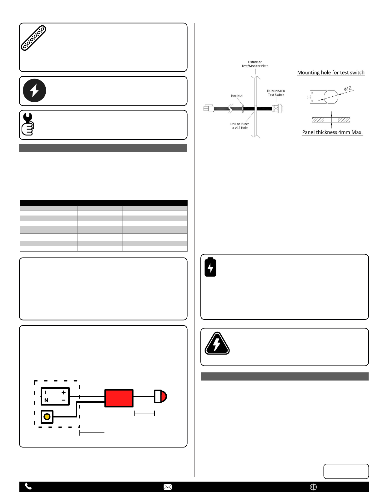
Mount the supplied 4 wire illuminated test switch in a location that is
visible and accessible by maintenance personnel. The switch mounts
through a hole which may need to be added to the luminaire or could
come pre-punched by the luminaire supplier.
Wire the test switch per wiring diagrams provided on this instruction.
5.
If wired correctly, the test switch indicator light should be ON when AC
power is supplied to the fixture, and the battery switch is “ON”
indicating that the emergency battery is charging.
NOTE:
For 10W models, a short term discharge test may be
conducted after the emergency driver has been charged for
one hour. A 24 hour charging period must be performed
before conducting a long term discharge test. For 20W models, a
short term discharge test may be conducted after the emergency
driver has been charged for one hour. A 48 hour charging period
must be performed before conducting a long term discharge test.
Refer to the OPERATION section of specs.
CAUTION:
This unit has more than one power connection point.
To reduce the risk of electric shock, disconnect both the
branch circuit breakers or fuses and emergency power
supplies before servicing.
OPERATION
PAGE 2 OF 4
O.R.-Revision C: 2/24/21
Disconnect AC power from the LED luminaire.
6.
Select the appropriate wiring diagram to connect the emergency
driver to the AC driver and LED load. Make sure all connections are in
accordance with the National Electrical Code and any local
regulations. After installation is complete, supply AC power to the
emergency driver and turn on battery switch/join battery connector. At
this point, power should be connected to both the AC driver and the
emergency driver, and the Charging Indicator Light should illuminate
indicating the battery is charging.
Emergency Part#
Application
Notes
EMG-LED-G2-10W
Integrated Moun�ng
EMG-LED-G2-10W-FLEX
Remote Mounting
Remote mount test switch
EMG-LED-G2-10W-LP
Integrated Moun�ng
EMG-LED-G2-10W-FLEX-CP
Remote Moun�ng
Flex for Chicago Plenum
EMG-LED-G2-10W-INTG-FLEX
Remote Moun�ng
Test Switch is integrated, Power Flex
EMG-LED-G2-20W-INTG-FLEX
Remote Moun�ng
Test Switch is integrated, Power Flex
EMG-LED-G2-20W
Integrated Mounting
EMG-LED-G2-20W-FLEX
Remote Mounting
During normal operation AC power is applied, to the driver, and the
charging indicator light is illuminated, which indicates that the battery
is being charged. When power fails, the emergency LED driver will
automatically switch to emergency power (internal battery), operating
the LED load for a minimum of 90 minutes. When AC power is
restored, the emergency driver returns to the charging mode.
Max
18ft
Contact
Elite
Emergency Test
Switch
Fixture

MAINTENANCE
10W Slim Emergency LED Driver
10W Emergency LED Driver
20W Emergency LED Driver
SYSTEM WIRING DIAGRAM
LED Emergency
Pack
LED Indicator
& Test Switch
Yellow/Black
White Brown
Yellow
Red
Blue
Constant
Hot
Neutral
Battery
Connector
Cap-Off
Cap-Off
*REFER ANY SERVICING INDICATED BY THESE CHECKS TO
QUALIFIED PERSONNEL
TCASE TEST POINT LOCATION
EMERGENCY DRIVER AND AC DRIVER MUST BE FED FROM THE
SAME BRANCH CIRCUIT TYPICALLY. IT MAY BE USED WITH
OTHER DRIVERS. CONSULT THE FACTORY FOR OTHER WIRING
DIAGRAM. PAGE 3 OF 4
O.R.-Revision C: 2/24/21
Although no routine maintenance is required to keep the emergency
driver functional, it should be checked periodically to ensure that it is
working. The following schedule is recommended:
1.
2.
Test the emergency operation of the fixture at 30 day intervals for a
minimum of 30 seconds. The LED load should operate at reduced
illumination.
Visually inspect the charging indicator light monthly. It should be
illuminated. If the charging indicator is off. Contact tech support.
3.
Conduct a 90 minute discharge test once a year. The LED load should
operate at reduced illumination for at least 90 minutes.
0-10V
Dimmer
1 10V
Gray
LED Emergency
Pack
AC LED Driver
LED Indicator
& Test Switch
Yellow/Black
White
White
Black
Red
Blue
Brown
Yellow
Red
Blue
Wall
Switch
Constant
Hot
Neutral
Battery
Connector
Violet
Cap-Off
Overall Wiring Diagram
Switched Hot
Emergency Only Wiring Diagram

Scenario 1: Hipot Test with Emergency LED Driver and
AC Driver
Caution:
PLEASE FOLLOW THE WIRING DIAGRAM BEFORE
DOING HIPOT TEST, OTHERWISE IT MIGHT CAUSE
DAMAGE TO THE EMERGENCY DRIVER OR AC DRIVER.
HIPOT TEST
TECHNICAL SPECIFICATIONS
Ground
Driver must be grounded
Scenario 2: Hipot Test with Emergency LED Driver
without AC Driver
Ground
Driver must be grounded
LED Emergency
Pack
LED Indicator
& Test Switch
Yellow/Black
White Brown
Yellow
Red
Blue
Neutral
Battery
Connector
Fig C: Short two input wires White,
Yellow/Black and open Black wire
Line
Ht terminal
1.5KV
5mA/1 sec
Test Voltage
Leakage Current
PAGE 4 OF 4
O.R.-Revision C: 2/24/21
There are two different scenarios for performing hipot test;
1) With an AC driver
2) Without an AC driver
Wiring diagrams for both scenarios are provided as below. Please
follow the wiring diagram before performing hipot testing. The
recommended setting is 1.5KV, 5mA/1sec
0-10V
Dimmer
1 10V
Gray
LED Emergency
Pack
AC LED Driver
LED Indicator
& Test Switch
Yellow/Black
White
White
Black
Red
Blue
Brown
Yellow
Red
Blue
Wall
Switch
Neutral
Battery
Connector
Violet
Fig B: Short all three input wires White, Yellow/Black,
Black, and cap offBlack from Emergency driver
Optional
ON
Line
Ht terminal
1.5KV
5mA/1 sec
Test Voltage
Leakage Current
In Figure A, we short all the input wires White, Yellow/Black and Black
wires together. Also, the user must ensure the optional wall switch is
“ON”. It is safe to begin hipot testing .
Ground
Driver must be grounded
In Figure B, all three input wires White, Yellow/Black and Black wire
from AC driver are shorted together. Also the user must ensure the
optional wall switch is “ON”. The black wire from Emergency LED driver
should also be "capped off" (left open) It is safe to begin hipot testing.
In Figure C, two input wires White and Yellow/Black are shorted, and
the Black wire is "capped off" (left open). It is safe to begin hipot
testing.
10W Model
20W Model
Input Voltage
120-277VAC
120-277VAC
Input Current
60mA
Input Power
10W Max
20W Max
Frequency
50/60Hz
50/60Hz
Output Voltage
15-55VDC
15-55VDC
Output Current
190mA
380mA
Ambient Temperature
0°C - 55°C
0°C - 55°C
Max Case Temperature
66°C
66°C
Baery Type
LiFePO4
LiFePO4
Installaon Type
Factory or Field
Factory or Field
Min Duraon Time
90min
90min
Recharge Time
24Hrs
Baery Voltage
6.4VDC
Baery Charge Current
185mA
0-10V
Dimmer
1 10V
Gray
LED Emergency
Pack
AC LED Driver
LED Indicator
& Test Switch
Yellow/Black
White
White
Black
Red
Blue
Brown
Yellow
Red
Blue
Wall
Switch
Neutral
Battery
Connector
Violet
Fig A: Short all three input wires White,
Yellow/Black and Black together
Optional
ON
Line
Ht terminal
1.5KV
5mA/1 sec
Test Voltage
Leakage Current
70mA
48Hrs
9.6VDC
210mA
This manual suits for next models
6
Popular Lighting Equipment manuals by other brands

Arcadia
Arcadia LumenIZE LEDBAR Installation and maintenance instructions

TMI Products
TMI Products MH2009231 Assembly instructions

VISICO
VISICO VISICO2 user manual

JB Systems
JB Systems Sirius Operation manual

Grid
Grid BROWS instruction manual

Lightolier
Lightolier Lighting Systems EG2-4 Specification sheet

Vision & Control
Vision & Control LDLF60x420-IR850/UDC installation guide

Focon Showtechnic
Focon Showtechnic Expolite led22385 user manual

Ikan
Ikan PT3700-TK quick start guide

Future light
Future light PRO Slim PAR-12 MK2 CW user manual

Aqua Creek Products
Aqua Creek Products Ranger 2 instruction manual

Philips
Philips Lightstrip Plus 71901/U8 Series user manual