Eliwell EWCFW-08 User manual
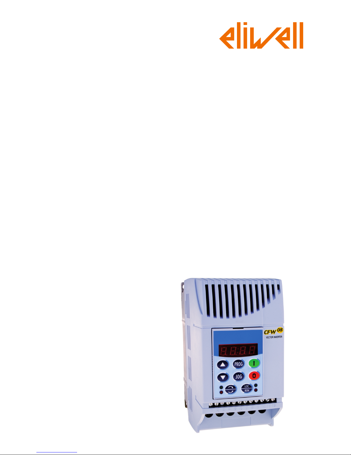
Frequency Inverter
EWCFW-08
User's Manual

07/2010
FREQUENCY
INVERTER
MANUAL
ATTENTION!
It is very important to check if the
inverter software version is the
same as indicated above.
Series: CFW-08
Software:version5.2X
Language:English
Document: 10000891866 / 00

2
Summary of Revisions
Thetablebelowdescribesallrevisionsmadetothismanual.
Revision Description Section
0 First Edition -

Summary
Quick Parameter Reference,
Fault and Status Messages
I Parameters.................................................................... 8
II FaultMessages ........................................................... 16
IIIOtherMessages........................................................... 16
CHAPTER 1
Safety Notices
1.1SafetyNotices intheManual ..................................... 17
1.2 SafetyNotices on the Product................................... 17
1.3PreliminaryRecommendations ................................. 17
CHAPTER 2
General Information
2.1AboutthisManual ...................................................... 19
2.2 Software Version....................................................... 19
2.3AbouttheCFW-08 .................................................... 20
2.4CFW-08 Identification ............................................... 24
2.5Receiving and Storing ............................................... 27
CHAPTER 3
Installation and Connection
3.1MechanicalInstallation .............................................. 28
3.1.1Environment........................................................ 28
3.1.2 Mounting Specifications...................................... 28
3.1.3 PositioningandFixing ........................................ 31
3.1.3.1PanelMounting.......................................... 32
3.1.3.2SurfaceMounting....................................... 33
3.2 ElectricalInstallation................................................. 33
3.2.1Power/ GroundingTerminals.............................. 33
3.2.2 Locationofthe PowerTerminals,Grounding
TerminalsandControlTerminalConnections...... 35
3.2.3 Power/GroundingWiringandCircuitBreakers .. 36
3.2.4 PowerConnections ............................................ 37
3.2.4.1 ACInputConnection................................ 39
3.2.4.2 OutputConnections .................................. 40
3.2.4.3 GroundingConnections............................ 40
3.2.5 Signaland ControlConnections ......................... 42
3.2.5.1 Digital Inputsas LowLevelActive
(S1:1 to OFF) ........................................... 46
3.2.5.2 DigitalInputasHighLevelActive
(S1:1to ON) ............................................. 47
3.2.6TypicalTerminalConnections ............................. 48
3.3 European EMCDirective-Requirements
forConformingInstallations ...................................... 51
3.3.1Installation ........................................................... 51

Summary
3.3.2 Emissionand ImmunityLevelsDescription ........ 52
3.3.3 InverterModels and Filters.................................. 54
3.3.4 EMC Filters Characteristics ............................... 57
CHAPTER 4
Keypad (HMI) Operation
4.1 Keypad (HMI) Description......................................... 67
4.2Useof the Keypad(HMI) ........................................... 68
4.2.1 Keypad Operation .............................................. 69
4.2.2InverterStatus ..................................................... 70
4.2.3Read-OnlyParameters ....................................... 71
4.2.4Parameter Viewingand Programming ............... 71
CHAPTER 5
Start-up
5.1 Pre-Power Checks.................................................... 74
5.2InitialPower-up.......................................................... 74
5.3Start-up...................................................................... 75
5.3.1 Start-up Operationvia Keypad(HMI)-
Type of Control: Linear V/F (P202 = 0)............... 76
5.3.2 Start-upOperationviaTerminals-
Control Mode: Linear V/F (P202 = 0) ................. 77
5.3.3 Start-upOperation via Keypad -
Control Mode: Vector (P202 = 2)........................ 78
CHAPTER 6
Detailed Parameter Description
6.1Symbols .................................................................... 83
6.2Introduction ................................................................ 83
6.2.1 Control Modes (V/F and Vector) ......................... 83
6.2.2 V/F Control ......................................................... 83
6.2.3 Vector Control (VVC).......................................... 84
6.2.4FrequencyReferenceSources ........................... 85
6.2.5 Commands......................................................... 88
6.2.6Local/Remote Operation Modes ........................ 88
6.3 Parameter Listing...................................................... 89
6.3.1 AccessandRead-onlyParameters-
P000 to P099 ..................................................... 90
6.3.2 Regulation Parameters - P100 to P199 ............. 92
6.3.3 Configuration Parameters - P200 to P398 ....... 102
6.3.4 Motor Parameters - P399 to P499 ................... 128
6.3.5 Special Function Parameters- P500 to P599 .. 131
6.3.5.1Introduction .............................................. 131
6.3.5.2 Description .............................................. 131
6.3.5.3PIDStart-up Guide................................... 134

Summary
CHAPTER 7
Diagnosticsand Troubleshooting
7.1 Faults and Possible Causes ................................... 141
7.2Troubleshooting....................................................... 144
7.3Contacting Eliwell.................................................... 145
7.4PreventiveMaintenance.......................................... 145
7.4.1CleaningInstructions......................................... 146
CHAPTER 8
CFW-08 Options andAccessories
8.1HMI-CFW08-P ........................................................ 149
8.1.1InstructionsforInsertionandRemovingof
theHMI-CFW08-P ............................................ 149
8.2TCL-CFW08 ........................................................... 149
8.3HMI-CFW08-RP...................................................... 150
8.3.1HMI-CFW08-RPInstallation.............................. 150
8.4MIP-CFW08-RP...................................................... 151
8.5 CAB-RP-1, CAB-RP-2, CAB-RP-3, CAB-RP-5,
CAB-RP-7.5, CAB-RP-10...................................... 151
8.6HMI-CFW08-RS...................................................... 151
8.6.1HMI-CFW08-RSInstallation.............................. 152
8.6.2HMI-CFW08-RS Start-up .................................. 152
8.6.3KeypadCopyFunction ..................................... 153
8.7MIS-CFW08-RS...................................................... 153
8.8 CAB-RS-1, CAB-RS-2, CAB-RS-3, CAB-RS-5,
CAB-RS-7.5, CAB-RS-10 ...................................... 153
8.9 KDC-24VR-CFW08................................................ 154
8.10 KDC-24V-CFW08................................................. 155
8.11 KCS-CFW08......................................................... 156
8.11.1 InstructionsforKCS-CFW08
InsertionandRemoval..................................... 157
8.12 KSD-CFW08 ........................................................ 157
8.13 KRS-485-CFW08 ................................................. 158
8.14 KFB-CO-CFW08 .................................................. 159
8.15 KFB-DN-CFW08 .................................................. 160
8.16 KAC-120-CFW08, KAC-120-CFW08-N1M1
KAC-120-CFW08-N1M2 ...................................... 162
8.17 KMD-CFW08-M1.................................................. 163
8.18 KFIX-CFW08-M1, KFIX-CFW08-M2 .................... 164
8.19KN1-CFW08-M1,KN1-CFW08-M2...................... 165
8.20RFIFilter ............................................................... 166
8.21 Line Reactor.......................................................... 167
8.21.1Application Criteria ....................................... 167
8.22 Load Reactor ........................................................ 170
8.23 Dynamic Braking................................................... 171
8.23.1ResistorSizing.............................................. 171
8.23.2Installation ..................................................... 172
8.24Serial Communication........................................... 173

Summary
8.24.1Introduction.................................................... 173
8.24.2RS-485 and RS-232Interfaces Description . 174
8.24.2.1RS-485 .............................................. 175
8.24.2.2RS-232 .............................................. 176
8.24.3 Definitions..................................................... 176
8.24.3.1UsedTerms ....................................... 176
8.24.3.2Parameter/Variables Resolution........ 177
8.24.3.3CharacterFormat .............................. 177
8.24.3.4Protocol ............................................. 177
8.24.3.5 Execution and Message Test............. 180
8.24.3.6 Message Sequence .......................... 180
8.24.3.7 Variable Code ................................... 180
8.24.4 Message Examples ...................................... 181
8.24.5 Variables and Errors of the Serial
Communication ............................................ 181
8.24.5.1 Basic Variables ................................. 181
8.24.5.2 Message Examples with Basic
Variables............................................ 184
8.24.5.3ParametersRelatedtotheSerial
Communication ................................... 185
8.24.5.4 ErrorsRelated tothe Serial
Communication ................................. 186
8.24.6Timefor Read/Write of Messages ................ 186
8.24.7PhysicalConnectionRS-232andRS-485.... 187
8.25Modbus-RTU......................................................... 188
8.25.1IntroductiontoModbus-RTUProtocol ........... 188
8.25.1.1Transmission Modes ......................... 188
8.25.1.2MessageStructure in RTUMode ...... 188
8.25.2Operation of the CFW-08 in the
Modbus-RTUNetwork .................................. 191
8.25.2.1RS-232andRS-485Interface
Description ....................................... 191
8.25.2.2 InverterConfigurationinthe
Modbus-RTU Network ..................... 191
8.25.2.3AccesstotheInverterData ............... 192
8.25.3Detailed Function Description ...................... 195
8.25.3.1 Function 01 -Read Coils .................. 195
8.25.3.2Function 03 - Read Holding Register 196
8.25.3.3Function 05- Write Single Coil ......... 197
8.25.3.4 Function 06- Write Single Register .. 198
8.25.3.5 Function15 - Write Multiple Coils...... 198
8.25.3.6Function16 -WriteMultipleRegisters199
8.25.3.7 Function 43 -Read Device
Identification ..................................... 200
8.25.4Modbus-RTUCommunicationErrors............ 202
8.25.4.1 Error Messages ............................... 203

Summary
CHAPTER 9
TechnicalSpecifications
9.1Power Data.............................................................. 204
9.1.1 200-240 V Power Supply.................................. 204
9.1.2 380-480 V Power Supply.................................. 205
9.2Electronics/General Data ........................................ 208
9.3 WEG StandardIV-Pole Motor Data......................... 209

8
CFW-08 - QUICK PARAMETER REFERENCE
Software: V5.2X
Application:
Model:
SerialNumber:
Responsible:
Date: / / .
I.Parameters
QUICK PARAMETER REFERENCE, FAULT AND STATUS MESSAGES
Parameter Function Adjustable Range Factory Unit User Page
Setting Setting
P000 ParameterAccess 0 to 4 = Read 0 - 90
5 = Alteration
6 to 999 = Read
READ ONLY PARAMETERS - P002to P099
P002 FrequencyProportional Value 0 to 6553 - - 90
(P208xP005)
P003 MotorOutputCurrent 0 to 1.5xInom - A 90
P004 DCLink Voltage 0 to 862 - V 90
P005 Motor Output Frequency 0.00 to 300.0 - Hz 90
P007 Motor Output Voltage 0 to 600 - V 90
P008 HeatsinkTemperature 25 to 110 - °C 91
P009 (1) MotorTorque 0.0 to 150.0 - % 91
P014 Last Fault 00 to 41 - - 91
P023 SoftwareVersion x . y z - - 91
P040 PID Process Variable 0 to 6553 - - 91
(Value % x P528)
REGULATION PARAMETERS - P100 to P199
Ramps
P100 Acceleration Time 0.1 to 999 5.0 s 92
P101 DecelerationTime 0.1 to 999 10.0 s 92
P102 Ramp2AccelerationTime 0.1 to 999 5.0 s 92
P103 Ramp2DecelerationTime 0.1 to 999 10.0 s 92
P104 S Ramp 0 = Inactive 0 - 92
1 = 50 %
2 = 100 %
Frequency Reference
P120 Digital ReferenceBackup 0 = Inactive 1 - 93
1 =Active
2 = Backup by P121
P121 KeypadReference P133 to P134 3.00 Hz 93
P122 JOGSpeedReference 0.00 to P134 5.00 Hz 94
P124 Multispeed Reference 1 P133 to P134 3.00 Hz 94
P125 Multispeed Reference 2 P133 to P134 10.00 Hz 94
P126 Multispeed Reference 3 P133 to P134 20.00 Hz 94
P127 Multispeed Reference 4 P133 to P134 30.00 Hz 95
P128 Multispeed Reference 5 P133 to P134 40.00 Hz 95
P129 Multispeed Reference 6 P133 to P134 50.00 Hz 95
P130 Multispeed Reference 7 P133 to P134 60.00 Hz 95
P131 Multispeed Reference 8 P133 to P134 66.00 Hz 95

9
CFW-08 - QUICK PARAMETER REFERENCE
Parameter Function Adjustable Range Factory Unit User Page
Setting Setting
(*) The factory default of parameter P136 depends on the inverter model as follows:
- models 1.6-2.6-4.0-7.0 A/200-240 V and 1.0-1.6-2.6-4.0 A/380-480 V: P136 = 5.0 %;
- models 7.3-10-16 A/200-240 V and 2.7-4.3-6.5-10 A/380-480 V: P136 = 2.0 %;
- models 22-28-33 A/200-240 V and 13-16-24-30 A/380-480 V: P136 = 1.0 %.
Speed Limits
P133 Minimum Frequency(Fmin) 0.00 to P134 3.00 Hz 95
P134 Maximum Frequency (Fmax) P133 to 300.0 66.00 Hz 96
V/F Control
P136 (2) (*) ManualTorqueBoost 0.0 to 30.0 5.0 or % 96
(IxRCompensation) 2.0 or
1.0 (*)
P137 (2) AutomaticTorque Boost 0.00 to 1.00 0.00 - 97
(AutomaticIxRCompensation)
P138 (2) SlipCompensation 0.0 to 10.0 0.0 % 97
P142 (2) (3) Maximum Output Voltage 0 to 100 100 % 98
P145 (2) (3) FieldWeakening P133 to P134 50.00Hzor Hz 98
Frequency(Fnom) 60.00 Hz
depending
on the
market
DC Link Voltage Regulation
P151 DCLinkVoltageRegulation 200 V models: 325 to 410 380 V 99
Level 400 V models: 564 to 820 780
Overload Current
P156 MotorOverloadCurrent 0.2xInom to 1.3xInom 1.2xP401 A 100
Current Limitation
P169 Maximum Output Current 0.2xInom to 2.0xInom 1.5xP295 A 101
Flux Control
P178 (1) Rated Flux 50.0 to 150 100 % 101
CONFIGURATION PARAMETERS - P200 to P398
Generic Parameters
P202 (3) ControlMode 0 = Linear V/F Control 0 - 102
(Scalar)
1 = Quadratic V/F Control
(Scalar)
2 = SensorlessVector Control
P203 (3) Special Function Selection 0 = No function 0 - 103
1 = PID Regulator
P204 (3) Load Factory Setting 0 to 4 = No Function 0 - 104
5 = Loads Factory Default
P205 DisplayDefault Selection 0 = P005 2 - 104
1 = P003
2 = P002
3 = P007
4, 5 = Not Used
6 = P040
P206 Auto-ResetTime 0 to 255 0 s 104
P208 ReferenceScaleFactor 0.00 to 99.9 1.00 - 104
P212 Frequency to Enable the Sleep 0.00 to P134 0.00 Hz 105
Mode
P213 Time Delayto Activate the 0.1 to 999 2.0 s 105
SleepMode
P215 (3) (4) Keypad Copy Function 0 = Not Used 0 - 106
1 = Copy(inverter keypad)
2 =Paste (keypadinverter)
P219 (3) Switching Frequency 0.00 to 25.00 6.00 Hz 107
Reduction Point

10
CFW-08 - QUICK PARAMETER REFERENCE
Parameter Function Adjustable Range Factory Unit User Page
Setting Setting
(**) Only available on the control board A2 (refer to item 2.4). For programming instructions, please, refer to the parameter P235 detailed
description.
Local/Remote Definition
P220 (3) Local/Remote 0 = Always Local 2 - 108
Selection Source 1 = Always Remote
2 = HMI-CFW08-P or
HMI-CFW08-RPKeypad
(default:local)
3 = HMI-CFW08-P or
HMI-CFW08-RPKeypad
(default:remote)
4 = DI2 to DI4
5=SerialorHMI-CFW08-RS
Keypad (default: local)
6=SerialorHMI-CFW08-RS
Keypad(default:remote)
P221 (3) FrequencyLocalReference 0 = Keypad and 0 - 109
Selection 1 = AI1
2, 3 = AI2
4 = E.P.
5 = Serial
6 = Multispeed
7 =Add AI0
8 = Add AI
P222 (3) FrequencyRemoteReference 0 = Keypad and 1 - 109
Selection 1 = AI1
2, 3 = AI2
4 = E.P.
5 = Serial
6 = Multispeed
7 =Add AI0
8 = Add AI
P229 (3) LocalCommand Selection 0 = HMI-CFW08-P or 0 - 109
HMI-CFW08-RPKeypad
1 = Terminals
2 = Serial or
HMI-CFW08-RSKeypad
P230 (3) RemoteCommandSelection 0 = HMI-CFW08-P or 1 - 109
HMI-CFW08-RPKeypad
1 = Terminals
2 = Serial or
HMI-CFW08-RSKeypad
P231 (3) Forward/ReverseSelection 0 = Forward 2 - 110
- Local and Remote 1= Reverse
2 = Commands
3 = DIx
Analog Input (s)
P233 Analog Input DeadZone 0 = Inactive 1 - 110
1 =Active
P234 AnalogInputAI1Gain 0.00 to 9.99 1.00 - 111
P235 (3) (5) Analog InputAI1Function 0 = (0 to 10) V/(0 to 20) mA / 0 - 112
(-10 to +10) V(**)
1 = (4 to 20) mA
2 = DI5 PNP
3 = DI5 NPN
4=DI5 TTL
5 = PTC

11
CFW-08 - QUICK PARAMETER REFERENCE
Parameter Function Adjustable Range Factory Unit User Page
Setting Setting
P236 AnalogInputAI1Offset -999 to +999 0.0 % 113
P238 (6) AnalogInputAI2Gain 0.00 to 9.99 1.00 - 113
P239 (3)(5)(6) Analog InputAI2 Function 0 = (0 to 10) V/(0 to 20) mA/ 0 - 113
(-10 to +10) V(**)
1 = (4 to 20) mA
2 = DI6 PNP
3 = DI6 NPN
4=DI6 TTL
5 = PTC
P240 (6) AnalogInputAI2Offset -999 to +999 0.0 % 113
P248 Analog Inputs Filter 0 to 200 10 ms 113
TimeConstant
Analog Output
P251 (6) AnalogOutput 0 = Output Frequency (Fs) 0 - 114
AO Function 1 = Input Reference (Fe)
2 = Output Current (Is)
3, 5, 8 = Not Used
4 = Motor Torque
6 = Process Variable (PID)
7 =Active Current
9 = PID Setpoint
P252 (6) AnalogOutputAO Gain 0.00 to 9.99 1.00 - 114
P253 Analog OutputAO Signal 0 = (0 to 10) V/(0 to 20) mA 0 - 114
1 = (4 to 20) mA
Digital Inputs
P263 (3) Digital Input DI1 Function 0 = No Function or General 0 - 115
Enable
1 to 7 and 10 to 12 =
GeneralEnable
8 = Forward Run
9 = Start/Stop
13 = FWD Run Using
Ramp2
14 = On
P264 (3) Digital Input DI2 Function 0=Forward/Reverse 0 - 115
1 = Local/Remote
2 to 6 and 9 to 12 = Not Used
7 = Multispeed (MS2)
8= Reverse
13 = REV Run - Ramp 2
14 = Off
P265 (3) (7) Digital Input DI3 Function 0=Forward/Reverse 10 - 115
1 = Local/Remote
2 = General Enable
3 = JOG
4 = No External Fault
5 = Increase E.P.
6 = Ramp 2
7 = Multispeed (MS1)
8 = No Function or
Start/Stop
9 = Start/Stop
10 = Reset
(**) Only available on the control board A2 (refer to item 2.4). For programming instructions, please, refer to the parameter P235 detailed
description.

12
CFW-08 - QUICK PARAMETER REFERENCE
Parameter Function Adjustable Range Factory Unit User Page
Setting Setting
11, 12 = Not Used
13 = Flying Start Disable
14 = Multispeed (MS1)
UsingRamp2
15 = Manual/Automatic (PID)
16 = Increase E.P. with
Ramp2
P266 (3) Digital Input DI4 Function 0=Forward/Reverse 8 - 115
1 = Local/Remote
2 = General Enable
3 = JOG
4 = No External Fault
5 = Decrease E.P.
6 = Ramp 2
7 = Multispeed (MS0)
8 = Not Used or
Start/Stop
9 = Start/Stop
10 = Reset
11, 12, 14and 15 = Not Used
13 = Flying Start Disable
16 = Decrease E.P. with
Ramp2
P267 (3) (5) Function of the Digital 0 = FWD/REV 11 - 115
Input DI5 (onlydisplayed 1 = Local/Remote
when P235 = 2, 3 or 4) 2 = General Enable
3 = JOG
4 = No External Fault
5 = Increase E.P.
6 = Ramp 2
7 = Multispeed (MS2)
8 = No Function or Start/Stop
9 = Start/Stop
10 = Reset
11 and 12 = Not Used
13 = Disables Flying Start
14 and 15 = Not Used
16 = Increase E.P. with
Ramp2
P268 (3) (5) (6) Function of the Digital 0 = FWD/REV 11 - 115
Input DI6 (onlydisplayed 1 = Local/Remote
when P239 = 2, 3 or 4) 2 = GeneralEnable
3 = JOG
4 = No External Fault
5 = Decrease E.P.
6 = Ramp 2
7 = Not Used
8 = No Function or Start/Stop
9 = Start/Stop
10 = Reset
11 and 12 = Not Used
13 = Disables Flying Start
14 and 15 = Not Used
16 = Decrease E.P. with
Ramp2

13
CFW-08 - QUICK PARAMETER REFERENCE
Parameter Function Adjustable Range Factory Unit User Page
Setting Setting
(*) It is not possible to set P297 = 7 (15 kHz) in vector control mode (P202 = 2) or when the external serial keypad (HMI-CFW08-RS) is used.
According
to the
inverter
model
DigitalOutput(s)
P277 (3) RelayOutput RL1 Function 0 = Fs > Fx 7 - 120
1 = Fe > Fx
2 = Fs = Fe
3 = Is>Ix
4 and 6 = Not Used
5 = Run
7 = No Fault
P279 (3) (6) RelayOutput RL2 Function 0 = Fs > Fx 0 - 120
1 = Fe > Fx
2 = Fs = Fe
3 = Is > Ix
4 and 6 = Not Used
5 = Run
7 = No Fault
Fx and Ix
P288 Fx Frequency 0.00 to P134 3.00 Hz 122
P290 IxCurrent 0 to 1.5xInom 1.0xInom A 122
Inverter Data
P295 (3) RatedInverter 300 = 1.0 A - 122
Current(Inom) 301 = 1.6 A
302 = 2.6 A
303 = 2.7 A
304 = 4.0 A
305 = 4.3 A
306 = 6.5 A
307 = 7.0 A
308 = 7.3 A
309 = 10 A
310 = 13 A
311 = 16 A
P297 (3) Switching Frequency 4 = 5.0 4 kHz 122
5 = 2.5
6 = 10
7 = 15 (*)
DC Braking
P300 DCBrakingTime 0.0 to 15.0 0.0 s 124
P301 DC Braking Start Frequency 0.00 to 15.00 1.00 Hz 124
P302 DCBrakingCurrent 0.0 to 130 0.0 % 124
Skip Frequencies
P303 Skip Frequency 1 P133 to P134 20.00 Hz 125
P304 Skip Frequency 2 P133 to P134 30.00 Hz 125
P306 Skip BandRange 0.00 to 25.00 0.00 Hz 125
Serial Communication Interface I
P308 (3) InverterAddress 1 to 30 (Serial Wbus) 1 - 125
1to247(Modbus-RTU)
Flying Start and Ride-Through
P310 (3) Flying Start and Ride-Through 0 = Inactive 0 - 126
1 = Flying Start
2 = Flying Start and
Ride-Through
3=Ride-Through
312 = 22 A
313 = 24 A
314 = 28 A
315 = 30 A
316 = 33 A

14
CFW-08 - QUICK PARAMETER REFERENCE
Parameter Function Adjustable Range Factory Unit User Page
Setting Setting
P311 VoltageRamp 0.1 to 10.0 5.0 s 126
Serial Communication Interface II
P312 (3) SerialInterface Protocol 0 = Serial WBus 0 - 127
1 = Modbus-RTU 9600 bps
without parity
2 = Modbus-RTU 9600 bps
with odd parity
3 = Modbus-RTU 9600 bps
withevenparity
4 = Modbus-RTU 19200 bps
without parity
5 = Modbus-RTU 19200 bps
with odd parity
6 = Modbus-RTU 19200 bps
withevenparity
7 = Modbus-RTU 38400 bps
without parity
8 = Modbus-RTU 38400 bps
with odd parity
9 = Modbus-RTU 38400 bps
withevenparity
P313 Serial InterfaceWatchdog 0 = Disabling by ramp 2 - 127
Action 1 = General disable
2 = Shows only E28
3 = Goes to local mode
P314 SerialInterfaceWatchdog 0.0 = Disables the function 0.0 s 128
Timeout 0.1 to 99.9 = Setvalue
MOTOR PARAMETERS - P399 to P499
Rated Parameters
P399 (1) (3) Rated Motor Efficiency 50.0 to 99.9 % 128
P400(1) (3) RatedMotorVoltage 0 to 600 V 128
P401 Rated MotorCurrent 0.3xP295 to 1.3xP295 A 128
P402(1) RatedMotor Speed 0 to 9999 rpm 129
P403 (1) (3) Rated Motor Frequency 0.00 to P134 Hz 129
P404 (1) (3) RatedMotorPower 0 = 0.16 HP / 0.12 kW - 129
1 = 0.25 HP / 0.18 kW
2 = 0.33 HP / 0.25 kW
3 = 0.50 HP / 0.37 kW
4 = 0.75 HP / 0.55 kW
5 = 1 HP / 0.75 kW
6 = 1.5 HP / 1.1 kW
7 = 2 HP / 1.5 kW
8 = 3 HP / 2.2 kW
9 = 4 HP / 3.0 kW
10 = 5 HP / 3.7 kW
11 = 5.5 HP / 4.0 kW
12 = 6 HP / 4.5 kW
13 = 7.5 HP / 5.5 kW
14 = 10 HP / 7.5 kW
15 = 12.5 HP / 9.2 kW
16 = 15 HP / 11.2 kW
17 = 20 HP / 15.0 kW
According
to the
inverter
model
(motor
matched
to the
inverter-
referto
item 9.3)
and sales
market

15
CFW-08 - QUICK PARAMETER REFERENCE
Parameter Function Adjustable Range Factory Unit User Page
Setting Setting
Notes foundontheQuickParameterReference:
(1) This parameteris onlydisplayed in vector mode (P202 = 2).
(2) This parameter is only displayed in scalar mode P202 = 0 or 1.
(3) This parametercan bechanged onlywhenthe inverteris disabled(stopped motor).
(4) ThisparameterisonlyavailablewithHMI-CFW08-RS.
(5) Theanaloginputvalueisrepresentedbyzerowhenitisnotconnectedtoanexternalsignal.
In order to use an analog input as a digital input with NPN logic (P235 or P239 = 3), it is
necessary to connect a 10 kresistor from terminal 7 to 6 (AI1) or 8 (AI2) of the control
terminalstrip.
(6) ThisparameterisonlyavailableintheCFW-08Plusversion.
(7) TheparametervaluechangesautomaticallywhenP203=1.
P407 (3) RatedMotorPower 0.50 to 0.99 - 130
Factor
Measured Parameters
P408 (1) (3) RunSelf-Tuning 0 = No 0 - 130
1 = Yes
P409 (3) Motor Stator Resistance 0.00 to 99.99 130
SPECIAL FUNCTION - P500 to P599
PID Regulator
P520 PID ProportionalGain 0.000 to 7.999 1.000 - 138
P521 PIDIntegralGain 0.000 to 9.999 1.000 - 138
P522 PIDDifferentialGain 0.000 to 9.999 0.000 - 138
P525 Setpoint (Via Keypad) of the 0.00 to 100.0 0.00 % 138
PIDRegulator
P526 Process Variable Filter 0.01 to 10.00 0.10 s 138
P527 PIDAction 0 = Direct 0 - 138
1= Reverse
P528 ProcessVariable 0.00 to 99.9 1.00 - 139
Scale Factor
P535 Wake up Band 0.00 to 100.00 1.00 % 139
P536 Automatic Setting of P525 0 =Active 0 - 140
1 = Inactive
According to
theinverter
model
(referto
item 9.3)
According to
theinverter
model

16
CFW-08 - QUICK PARAMETER REFERENCE
Display Description Page
E00 Outputovercurrent/short-circuit/outputgroundfault 141
E01 DClinkovervoltage 141
E02 DClinkundervoltage 142
E04 Overtemperature at the power heatsink or in the 142
inverterinternalair
E05 Outputoverload(Ixt function) 142
E06 External fault 142
E08 CPUerror(Watchdog) 142
E09 Programmemoryerror(Checksum) 142
E10 Keypad copy function error 142
E14 Self-tuning routine(estimation of the motor 142
parameters)error
E22,E25, Serialcommunicationerror 142
E26 and E27
E24 Programmingerror 142
E28 Serial interfaceWatchdogtimeouterror 143
E31 Keypadconnectionfault (HMI-CFW08-RS) 143
E32 Motorovertemperature(externalPTC) 143
E41 Self-diagnosisfault 143
II.FaultMessages
III.OtherMessages Display Description
rdy Inverter is readyto be enabled
Sub Power supplyvoltage is too low for the inverter
operation(undervoltage)
dcbr InverterinDCbrakingmode
auto Inverterisrunningself-tuningroutine
copy Keypad copyfunction in progress (onlyavailable in
theHMI-CFW08-RS)-inverterto keypad
past Keypad copyfunction in progress (only available in
theHMI-CFW08-RS)-keypadto inverter
Srdy Inverter in the sleep rdymode
17
CHAPTER1
SAFETYNOTICES
This Manual contains necessary information for the correct
useoftheCFW-08frequencyinverter.
This Manual was developed for qualified personnel with
suitabletrainingandtechnicalqualificationtooperatethistype
ofequipment.
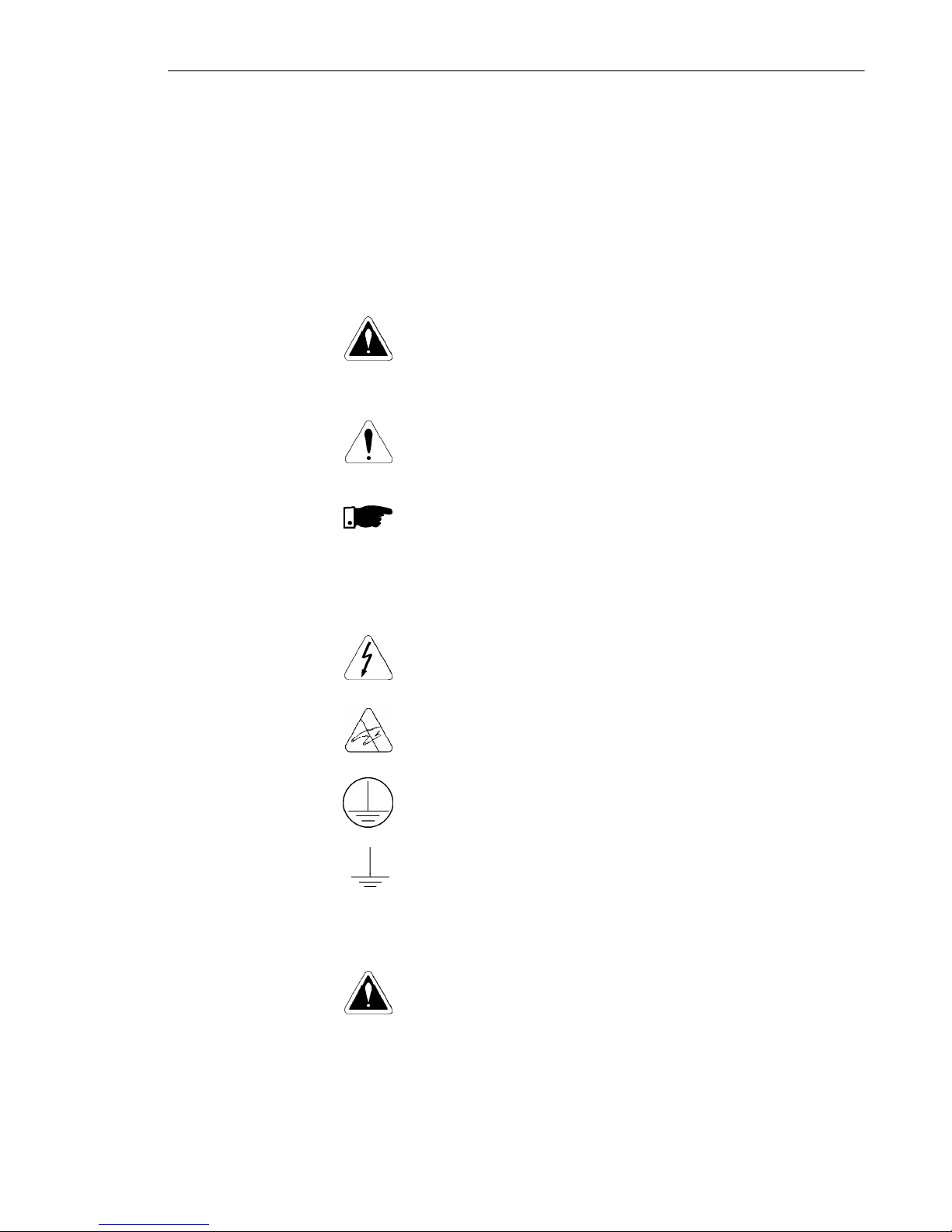
Thefollowingsafetynoticesareusedinthismanual:
DANGER!
Iftherecommendedsafetynoticesarenotstrictlyobserved,it
canleadtoseriousorfatalinjuriesofpersonneland/ormaterial
damage.
ATTENTION!
Failure to observetherecommended safetyprocedurescan
lead to material damage.
NOTE!
This notice provides important information for the proper
understandingandoperationoftheequipment.
Thefollowingsymbolsmaybeattachedtotheproduct,serving
assafetynotice:
High Voltages.
Componentssensitive to electrostaticdischarge. Do not
touch them without proper grounding procedures.
Mandatory connection to ground protection (PE).
Shield connection to ground.
DANGER!
Only qualified personnel should plan or implement the
installation, start- up, operation and maintenance of this
equipment. Personnel must review entire Manual before
attempting to install,operate ortroubleshoot the CFW-08.
Thesepersonnel mustfollowall safetyinstructionsincluded
in this manual and/ordefinedbylocal regulations.
Failure to comply with these instructions may result in
personnelinjuryand/orequipmentdamage.
1.3 PRELIMINARY
RECOMMENDATIONS
1.2 SAFETYNOTICES
ONTHEPRODUCT
1.1 SAFETYNOTICESIN
THEMANUAL

18
CHAPTER 1 - SAFETY NOTICES
NOTE!
Inthismanual,qualifiedpersonnelare definedaspeoplethatare
trainedto:
1. Install,ground,power upandoperatetheCFW-08according
tothismanual andthelocal requiredsafetyprocedures;
2. Useofsafetyequipmentaccordingtothelocalregulations;
3. Administer FirstAid.
DANGER!
Theinvertercontrol circuit(ECC3,DSP)andtheHMI-CFW08-P
arehigh voltagecircuitsand are not grounded.
DANGER!
Always disconnect the supply voltage before touching any
electricalcomponentinside theinverter.
Many components are charged with high voltage and/or in
movement(fans), even afterthe incomingAC powersupplyhas
beendisconnectedorswitchedOFF. Waitatleast10minutesfor
the total dischargeof the powercapacitors.
Alwaysconnecttheframeoftheequipmenttotheground (PE)at
thesuitableconnectionpoint.
ATTENTION!
All electronic boards have components that are sensitive to
electrostatic discharges. Never touch any of the electrical
components or connectors without following proper grounding
procedures. If necessaryto do so, touch the properlygrounded
metallic frame oruse asuitable groundstrap.
NOTE!
Inverterscaninterferewithotherelectronicequipment.Inorderto
reduce this interference, adopt the measures recommended in
chapter3-InstallationandConnection.
NOTE!
ReadthisentiremanualbeforeinstallingoroperatingtheCFW-08.
Do not apply high voltage (high pot) test on the inverter!
If this test is necessary, contact Eliwell.

19
Thischapterdefinesthecontentsandpurposesofthismanu-
al and describes the main characteristics of the CFW-08
frequency inverter. Identification, receiving inspections and
storagerequirements are also provided.
This manualis divided into9 chapters, providinginformation
to the user on how receive, install, start-up and operate the
CFW-08.
Chapter 1 - Safetynotices.
Chapter 2 - GeneralinformationandreceivingtheCFW-08.
Chapter 3 - RFI filters,mechanical and electrical installation
(powerandcontrolcircuit).
Chapter 4 - Using the keypad (Human Machine Interface -
HMI).
Chapter 5 - Start-upand stepstofollow.
Chapter 6 - Setup and read only parameters detailed
description.
Chapter 7 - Solving problems, cleaning instructions and
preventivemaintenance.
Chapter 8 - CFW-08 optional devices description, technical
characteristicsandinstallation.
Chapter 9 - CFW-08ratings,tablesandtechnicalinformation.
This manual provides information for the correct use of the
CFW-08. This frequency inverter is very flexible and allows
the operation in many different modes as described in this
manual.
AstheCFW-08canbeappliedinseveralways,itisimpossible
todescribeherealloftheapplicationpossibilities.Eliwelldoes
not accept any responsibility when the CFW-08 is not used
accordingto this manual.
Nopartofthismanualmaybereproducedinanyform,without
thewrittenpermissionofEliwell.
It is important to note the software version installed in the
CFW-08,sinceitdefinesthefunctionsandtheprogramming
parameters of the inverter.
This manual refers to the software version indicated on the
insidecover.Forexample,theversion3.0Xappliestoversions
3.00 to 3.09, where “X” is a variable that will change due to
minor software revisions. The operation of the CFW-08 with
these software revisions are still covered by this version of
themanual.
The software version can beread in the parameterP023.
GENERALINFORMATION
2.1 ABOUTTHIS
MANUAL
2.2 SOFTWARE
VERSION
CHAPTER2
Other manuals for EWCFW-08
1
Table of contents
Other Eliwell DC Drive manuals


Popular DC Drive manuals by other brands

Siemens
Siemens SINAMICS SM150 6SL3815-7NP41-0AA1 Operating instructions & installation instructions

ABB
ABB ACS880 Series Supplement

Xinje
Xinje DP3F Series user manual

RHINO
RHINO RMCS-3002 operating manual

Unimotion
Unimotion MCE Assembly and maintenance instructions

SEW-Eurodrive
SEW-Eurodrive MOVIMOT D EtherNet/IP Compact manual


