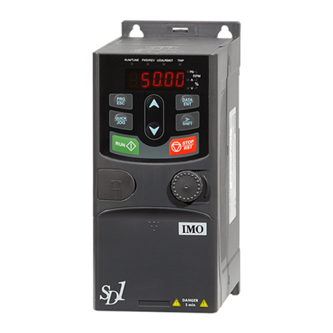
Eliwell V800 Series User manual

V800
/P1 /P2 /P3 /P4
Driver for electronic expansion valve
Driver per valvola espansione elettronica
Controlador para válvula de expansión electrónica
EN
IT
ES

2 - ENV800
AVAILABLE MODELS, COMPONENTS & ACCESSORIES .......3-EN
COMPATIBLE VALVE LIST ................................................5-EN
MECHANICAL ASSEMBLY................................................6-EN
ELECTRICAL CONNECTIONS ..........................................7-EN
Wiring diagram description ...........................................7-EN
WIRING DIAGRAM............................................................9-EN
V800 with door open .........................10-EN
TECHNICAL DATA ...........................................................11-EN
CONDITIONS OF USE - PERMITTED USE ..................13-EN
PROHIBITED USE .............................................................13-EN
LIABILITY AND RESIDUAL RISKS .................................13-EN
USER INTERFACE .............................................................14-EN
IWK/V Keys ...........................................14-EN
LED Table ...............................................15-EN
DipSwitch Table ...................................15-EN
ACCESSING AND USING THE MENUS .......................17-EN
STATES MENU .................................................................17-EN
Setting the overheating Setpoint ....17-EN
Active alarm ..........................................17-EN
Probe display ........................................17-EN
USB COPY CARD .............................................................18-EN
USB Copy Card DipSwitch ................18-EN
USB Copy Card DipSwitch LED ........19-EN
SUPERVISION .................................................................19-EN
DipSwitch Protocol Selection...........20-EN
ALARMS ............................................................................21-EN
FUNCTIONING..................................................................24-EN
REGULATION.....................................................................25-EN
APPLICATIONS..................................................................26-EN
Stand-Alone ..........................................26-EN
Typical application ..............................26-EN
Application with multiple V800
drivers / ID985/V controllers ...........27-EN
Application with 2 V800 drivers -
1 ID985/V controller ..........................28-EN
PARAMETERS TABLE ......................................................29-EN
DISCLAIMER......................................................................33-EN

3 - EN V800
AVAILABLE MODELS, COMPONENTS & ACCESSORIES
Code Model Valve control RS485 Notes
EVD2A43BSC000 V800/P1 Imax = 300mA@230VaYes AC Output • on-board RS485
EVD2A43BXC000 V800/P2 Imax = 300mA@230VaNo AC Output
EVD2A53BSC000 V800/P3 Imax = 300mA@230VcYes DC Output • on-board RS485
EVD2A53BXC000 V800/P4 Imax = 300mA@230VcNo DC Output
Code Model Description Notes
ID34DR4SCDH00 ID985/V
Electronic controller for ventilated refrigeration units with V800 driver management via LAN
serial connection See 9MAX0017 manual
WK1400100N000 IWK/V Remote terminal for parameter conguration, I/O display, alarms etc. See 9IS60000 instructions
See User Interface

4 - ENV800
Code Model Description Notes
EVK2A43BXC010 Standard Kit
includes
1 x ID985/V
1 x V800/P2
SN8P0X3002 1 x NTC ‘FAST’
probe
TD400030 1 x ratiometric probe
EVK2A43BXC020 Starter Kit
includes
1 x ID985/V
1 x V800/P2
SN8P0X3002 1 x NTC ‘FAST’
probe
TD400030 1 x ratiometric probe
CCA0BUI02N000 1 x USB
Copy Card
DMP1000002000 1 x Device
Manager CD
1 x Device Manger interface
DMI100x002000 Device Manager
Interface USB/TTL hardware interface for use in conjunction with the Device Manager software
x=1: End User
x= 2: Service
x= 3: Manufacturer

5 - EN V800
COMPATIBLE VALVES LIST
Eliwell guarantees electrical compatibility with following PULSE valves
Brand Model Brand Model
Eliwell manufactured
by Castel PXV ALCO EX2
Danfoss AKV10 PARKER HP130
Danfoss AKV15 PARKER DS1120
Danfoss AKV20
Danfoss AKV20
Danfoss AKVA (NH3)
Note : V800 Driver delivers to the valve the same voltage as its own supply voltage
Select carefully the suitable valve coil depending on the local power distribution network
For use with different valves please contact Eliwell Technical Customer Support

MECHANICAL ASSEMBLY
The device is designed for mounting on DIN guides.
The admissible ambient temperature range for correct operation is between –10 and 55 °C.
Also avoid tting the device in places where there is high humidity and/or dirt; it is suitable for use in environ-
ments with an ordinary or normal level of pollution. Keep the area around the instrument cooling slots adequately
ventilated.
Access to dip switches and connector for USB Copy Card / IWK/V
Remove the door (see gure below right) using a slotted screwdriver or the nail of your index nger.
Congure the dip switches and/or connect the USB Copy Card or connect IWK/V.
After having made the congurations, close the front panel of the keypad by pressing it with your ngers.
ID 985/V
56.4mm
5.2mm
87mm
70.2mm
61.6mm
43.6mm

7 - EN V800
ELECTRICAL CONNECTIONS
Important! Make sure the machine is switched off before working on the electrical connections. The instru-
ment is equipped with screw-on terminal boards for connection of electrical cables with a diameter of 2.5 mm2
(one conductor only per terminal for power connections): for the capacity of the terminals, see the label on the
instrument. The relay outputs are voltage free. Do not exceed the maximum permitted current; for higher loads, use
a contactor with sufcient power capacity.
Make sure that power supply is of the correct voltage for the instrument. NTC probes have no connection polar-
ity and can be extended using a normal bipolar cable (note that if the probes are extended this inuences the
device's electromagnetic compatibility - EMC: take great care with the wiring). Probe cables, power supply cables
and serial cables should be routed separately from power cables. The pressure/ratiometric probe has a connection
polarity which must be observed.
Wiring diagram description
Terminal Label Description Notes Par. / Notes
2-3-4 RS485 Televis/Modbus serial port models /P1 /P3 only models /P1 /P3 only
6-7-8 DO1 Relay output (6= C; 7= NC; 8= NO) H21
9-10 Supply Power Supply 100...240Va (9= L; 10= N)
11-12 Valve Output Valve Output (11= VO; 12= VO) AC Valve Output models /P1 /P2
DC Valve Output models /P3 /P4

8 - ENV800
Terminal Label Description Notes Par. / Notes
14 DI1 Digital input 1 it is strictly prohibited
to connect the Digital
Input to a power source
H11, H30
15 DI2 Digital Input 2 H12, H30
16 DO2 Open Collector Output H22
17 GND Ground
18 AO1 Analogue Output repeat in 0-10V scale VO valve output (terminals 11-12)
19 AI1 Analogue Input 1 overheating probe H00 congurable NTC/4...20mA*
20 5VcProbes Power Supply **Power supply for ratiometric probe (terminal 21)
21 AI2 Analogue Input 2 saturation probe H01 congurable NTC/4...20mA*/0-5V (ratiomet-
ric)**/ LAn (remote, shared pressure transducer)
22 12VcProbes Power Supply *Power supply for 4...20mA current input (terminals 19/ 21)
23-24 LAN Powered serial port ID985/V connection
DMI/CC Serial port for connection to
• USB Copy Card / • IWK/V See DipSwitch
TTL Serial port for connection
to Televis / Modbus PtS, dEA, FAA, PtY, Ptb

9 - EN V800
DO1
V800
NONC
CVOVO
N
L
RS-485
/P1 /P3 Models
only
Supply
100...240Vac
Televis/
Modbus
(use BusAdapter)
Televis/
Modbus
(direct connection)
7 8
9 10 11 12
6
19 20 21 22 23 2418
-+
G
3 42
5VcAI1
AO1 GNDLAN
12Vc
AI2
15 16 1714
DO2DI2
DI1 GND
Valve Output
AC output /P1 /P2
DC output /P3 /P4
Check carefully
ON
12
ON
34
ON
56
ON
78
ON
910
DMI/CC
Keyb
A
B
C
20 21 22 23 24
12Vc
AI2
I
SIG +
20 21 22 23 24
5VcGND
AI2
V
SIG + -
NTC
4...20mA
ratiometric
0-5V
19 20 21 22 23 24
AI1 GND
AI2
15 16 1714
DI2
default configuration
DI1 GND
19 20 21 2218
12Vc
16 17
DO2
Open Collector
LOAD
max 35mA
I
SIG +
‘Stand-Alone’ mode alone
repeats
Valve Output
scale 0-10V
WIRING DIAGRAM

10 - ENV800
ON
12
ON
34
ON
56
ON
78
ON
910
TTL
A
B
CTTL
IWK/V rear
Supply from V800
1 2 3 4 5 6 7 8 9
+
14 15 16 17 18 19 20
A B C D
LAN
SUPPLY
100...240Va 2.5W max
TTL
LAN
GND
+-
-
12 13
ID985/V
+-
set
f nc
IWK/V
%T1 T2 ∆T
DO1
V800
NONC
CVOVO
N
L
RS-485
/P1 /P3 Models
only
Supply
7 8
9 10 11 12
6
19 20 21 22 23 2418
-+
G
3 42
5VcAI1
AO1 GNDLAN
12Vc
AI2
15 16 1714
DO2DI2
DI1 GND
Valve Output
ON
12
ON
34
ON
56
ON
78
ON
910
Keyb
A
B
C
CIRCUIT DIAGRAM - V800 with open door
USB Copy Card connection
• Display DipSwitch and use of DMI/CC
connector for USB/Copy Card
IWK/V / LAN connection
• Display DipSwitch and use of Keyb connector for IWK/V.
• Display LAN connection with ID985/V

11 - EN V800
TECHNICAL DATA
Container: PC+ABS UL94 V-0 plastic resin casing
Dimensions: front 70.2x87 mm, depth 61.6 mm
Mounting: on DIN guide
Terminals: screw-on for cables with a diameter of 2.5 mm2
Serials: • TTL (DMI/CC) for connection to USB Copy Card or IWK/V remote terminal.
• TTL for Televis / Modbus connection
models /P1 /P3 only: RS485 for direct connection to Televis / Modbus
LAN: for connection to powered 3-wire interface. Max. distance 100m
Temperature: • Operating: –10 … +55 °C
• Storage: –30 … +85 °C
Ambient operating and storage humidity: 10…90% RH (non-condensing).
Analogue inputs: 2 • 1 NTC congurable input / 4...20mA
• 1 NTC congurable input / 4...20mA / 0-5V / LAn (remote,shared pressure transducer)
Digital inputs: 2 2 congurable voltage-free inputs
Digital outputs: 2
• 1 SPDT relay: N.O. 5A 250Va, N.C. 2A 250Va
• 1 Open Collector, max current 35mA. Load shall be siupplied through 12V available
on terminal 22.
Analogue output: 1 output 0-10V max. load 20mA.
Resolution 0.1%; Accuracy 1% e.o.s.
Measurement range: from –55 to 140 °C.
Accuracy: better than 0.5% of full-scale +1 digit.
Resolution: 1 or 0.1 °C.
Power draw: 3 VA coil consumption excluded.
Power supply: 100...240Va ±10% 50/60 Hz

12 - ENV800
•
For each circuit, type of disconnection or interruption : disconnection microswitch
•
PTI of materials used for insulation : PTI 250V
•
Period of electrical stress on the insulating parts : long period
The device is classied as follows :
•
According to the manufacturing type : integrated temperature-sensitive automatic electronic control device
•
According to the automatic operation characteristics : action type 1B control device
•
Relating to software class and structure : Class A device
•
Relating to the pollution control : class 2 (normal) device
•
Relating to the re and heat resistance : category D
•
According to over voltage category : class II device

13 - EN V800
CONDITIONS OF USE - PERMITTED USE
For safety reasons, the device must be installed and used according to the instructions provided. In particular,
parts carrying dangerous voltages must not be accessible in normal conditions.
The device must be adequately protected from water and dust with regard to the application, and must only be
accessible using tools (with the exception of the front panel).
The device is suitable for use in household refrigeration appliances and/or similar equipment and has been tested
for safety aspects in accordance with the harmonised European reference standards. It is rated:
• according to its construction, as an independently mounted automatic electronic control device;
• in terms of automatic operating characteristics, as a type 1B controller;
• in terms of software class and structure, as a Class A controller.
PROHIBITED USE Any use other than that expressly permitted is prohibited.
Note that the relay contacts provided are of a functional type and subject to failure: any protection devices
required by product standards, or suggested by common sense for obvious safety requirements, must be installed
externally to the instrument.
LIABILITY AND RESIDUAL RISKS
ELIWELL CONTROLS SRL declines any liability for damage due to:
• installation/uses other than those expressly specied and, in particular, failure to comply with the safety require-
ments of established standards and/or instructions specied in this document;
• use on panels that do not provide adequate protection against electric shocks, water or dust when assembled;
• use on panels allowing access to dangerous parts without having to use tools;
• tampering with and/or modication of the product;
• installation/use on panels which are not compliant with current standards and regulations.

14 - ENV800
USER INTERFACE
To operate on V800 use a IWK/V remote terminal connected to the TTL connector (DMI/CC) and supplied directly
from V800.
Connect the cable supplied with the IWK/V to the connector housed inside the door on the front panel.
IWK/V Keys
Key Description Key Description
UP
Scrolls through menu items fnc fnc Exits the menu (ESC)
Increases values
Displays values:
• %: valve opening percentage
• DT: overheating
• T2: saturation temperature
• T1: overheating temperature
LED ON when the corresponding
value appears on the display set set
Displays alarms - if alarms active
DOWN
Scrolls through menu items Accesses menus
Decreases values press for at least 5 secs.
Opens the programming menu
Displays values - See UP key Conrms commands

15 - EN V800
LED Table
LED colour ON blinking OFF Notes
EEV (PXV) green valve control valve closed
setpoint reached /
EEV (PXV)
LED OFF
means no power supply
Defrost yellow defrost ON
(valve closed) /no serial
connection
/ Defrost
Alarm red NA Alarm / Alarm
DipSwitch Table
Dip1 2 3 4 5 6 7 8 9 10
Function Upload / Download parameters from Copy Card
Upload ON OFF /
Download OFF ON /
Protocol Protocol Selection
LAN OFF /
Televis*/Modbus
*Set Ptb parameter = 96 (96000 baud) ON /

16 - ENV800
Dip1 2 3 4 5 6 7 8 9 10
Refrigerant Refrigerant selection
0 R404A OFF OFF OFF /
1 R22 ON OFF OFF /
2 R410A OFF ON OFF /
3 R134A ON ON OFF /
4 R744 (CO
2
) OFF OFF ON /
5 R507A ON OFF ON /
6
refrigerant customisable via USB
Copy Card / Device Manager
Default setting R717(NH3)
OFF ON ON /
7 set from parameter H10 ON ON ON /
Slave address Network address selection
1 OFF OFF OFF /
2 ON OFF OFF /
3 OFF ON OFF /
4 ON ON OFF /
5 OFF OFF ON /
6 ON OFF ON /
7 reserved DO NOT use OFF ON ON /
8 reserved DO NOT use ON ON ON /
Note: Dip10 is NOT used

17 - EN V800
ACCESSING AND USING THE MENUS
Resources are organised into menus and viewed by briey tapping the ‘set’ key (‘Machine state’ menu) or by
keeping the ‘set’ key pressed for more than 5 seconds (‘Programming’ menu). Press the ‘set’ key once to view the
contents of any folder highlighted by the corresponding label.
At this point it will be possible to scroll through the contents of the folder and edit it or use the functions it con-
tains. Either do not press any keys for 15 seconds (time-out) or press the ‘fnc’ key once, to conrm the last value
displayed and return to the previous screen.
STATES MENU (SETPOINTS / PROBES / ALARMS)
To access the ‘States’ menu press and release the ‘set’ key.
If no alarms are active, the ‘SEt’ label appears. Use the ‘UP’ and ‘DOWN’ keys to scroll through the other resources
in the menu.
Setting the Overheating Setpoint
Press and release the ‘set’ key. The ‘SEt’ folder label appears. To display the Setpoint value press the ‘set’ key once
again. The Setpoint value appears on the display. To change the Setpoint value, press the ‘UP’ and ‘DOWN’ keys
within 15 seconds. If the parameter LOC = y the Setpoint cannot be modied.
Active alarm
Press and release the ‘set’ key. If there is an active alarm condition, the ‘AL’ folder label will appear (see ‘Alarms’
section).
Probe display
When the corresponding label is displayed, pressing ‘set’ displays the value of the probe on the associated label.

18 - ENV800
USB COPY CARD
The USB Copy Card is an accessory connected to the DMI/CC serial port and is used for quick programming of the
device parameters (upload and download a parameter map to one or more devices of the same type). The opera-
tions are performed as follows:
• insert USB Copy Card in the suitable connector with device ON
• set DipSwitch 1 and 2, which are housed inside the door, as described in the following table
• wjen completed remove the USB Copy Card
• set DipSwitch to OFF position
Dip Switch USB Copy Card
Upload / Download parameters from USB Copy Card
Function Dip1 2
Upload ON OFF
Download OFF ON
UPLOAD: device --> USB Copy Card This operation
uploads the programming parameters to the USB
Copy Card.
NOTE: USB Copy Card will be formatted before use
DOWNLOAD: USB Copy Card --> device This opera-
tion downloads the programming parameters to the
device.

19 - EN V800
USB Copy Card Dip Switch LED
LED UPLOAD DOWNLOAD
colour in progress completed correctly failed in progress completed correctly failed
A green blinking ON ON / / /
B green / / / blinking ON ON
C yellow / / blinking / / blinking
NOTE:
• after the parameters have been downloaded, the device uses the downloaded parameter map settings.
SUPERVISION
The protocol can be modied without using the IWK/V remote terminal by positioning DipSwitch 3, which is
housed inside the door, as described in the next page table:
LAN
The LAN function makes it possible to link up to 4 ID985/V devices connected to V800 in a network (see ID985/V
manual, code 9MAX0017). The maximum distance between one device and the other must not exceed 7 metres,
while the maximum distance between the rst and the last device in the network must be approximately 50m.
Televis/Modbus
The connection to TelevisSystem / Modbus RTU can take place:
• via TTL serial port. It is necessary to use the TTL/RS485 converter BusAdapter 130 or 150
• models /P1 /P3 only directly via RS485 serial port.

20 - ENV800
(To congure the device for this purpose, open the folder identied by the ‘Add’ label and use parameters:
• PtS to select the TelevisSystem / Modbus RTU protocol
• TelevisSystem: dEA and FAA.
• Modbus RTU: dEA / FAA / PtY for the parity / Ptb for the baud rate.
NOTE: the connection serial port between the devices is powered.
Dip Switch Protocol Selection
Protocol Selection LED C
Protocol 3 yellow
LAN OFF OFF
Televis/Modbus ON ON
LAN
DipSwitch3=OFF only for use with IWK/V
NOTE: TTL port shall NOT be connected to any
device
Televis/Modbus
DipSwitch3=ON per Televis/Modbus supervision or use
with DMI/CC
NOTA: IWK/V shall NOT be connected
This manual suits for next models
4
Table of contents
Languages:
Other Eliwell DC Drive manuals
