TLV SJHX Series User manual

SJHX / SJH SERIES (OPTION: SJHB)
SJHX / SJH SERIE (OPTION: SJHB)
GAMME SJHX / SJH (OPTION : SJHB)
INSTRUCTION MANUAL
EINBAU- UND BETRIEBSANLEITUNG
MANUEL D UTILISATION
Keep this manual in a safe place for future reference
Gebrauchsanleitung leicht zugänglich aufbewahren
Conserver ce manuel dans un endroit facile d'accès
SJH3VX / SJH5VX / SJH7VX
SJH3V / SJH5V / SJH7V
SJH3NX / SJH5NX / SJH6NX / SJH7NX
SJH3N / SJH5N / SJH6N / SJH7N
Copyright (C) 2020 by TLV CO., LTD. All rights reserved.
FREE FLOAT TYPE STEAM TRAPS
FREI-SCHWIMMER-KONDENSATABLEITER
PURGEURS DE VAPEUR À FLOTTEUR FERMÉ LIBRE
Deutsch
Français
English

Introduction
Before beginning installation or maintenance, please read this manual to ensure correct usage of
the product. Keep the manual in a safe place for future reference.
The inline repairable SJHX / SJH Series steam traps with thermostatic air vent
(SJHX: X-element, SJH: bimetal) are suitable for a wide range of applications with small-to-large
capacities and pressures up to 32 barg (46 barg for SJH with PN 63 flange), such as heat
exchangers, tank heaters, dryers and process equipment. The traps discharge condensate
continuously and automatically, at a temperature slightly lower than saturation temperature.
1 MPa = 10.197 kg/cm2, 1 bar = 0.1 MPa
For products with special specifications or with options not included in this manual, contact
TLV for instructions.
The contents of this manual are subject to change without notice.
Einführung
Bitte lesen Sie die Betriebsanleitung vor Einbau und Inbetriebnahme sorgfältig durch und
bewahren Sie sie für späteren Gebrauch an einem leicht zugänglichen Ort auf.
Die in der Leitung wartbaren Schwimmerkugel-Kondensatableiter der SJHX / SJH Serie, mit
thermischem Entlüfter (SJHX mit X-Element, SJH mit Bimetall) können für alle Anlagengrößen und
mit Betriebsdrücken bis 32 bar ü eingesetzt werden (SJH mit PN 63 Flansch bis 46 bar ü). Sie
eignen sich besonders für Anwendungen, bei denen Kondensat mit geringer Unterkühlung unter
Sattdampftemperatur abgeleitet werden soll, insbesondere für Wärmetauscher,
Behälterbeheizungen, Tockner und Prozessanlagen aller Art.
1 bar = 0,1 MPa
Wenden Sie sich an TLV für Sonderausführungen, die nicht in dieser Einbau- und Betriebs-
anleitung enthalten sind.
Wir behalten uns vor, den Inhalt dieser Betriebsanleitung ohne Ankündigung zu ändern.
Introduction
Veuillez lire attentivement ce manuel afin de vous assurer d'utiliser correctement le produit. Nous
vous recommandons de le garder dans un endroit sûr pour de futures consultations.
Les purgeurs vapeur de la gamme SJHX/SJH avec purge d'air thermostatique (SJHX : élément X,
SJH : bimétallique) peuvent être utilisés pour une large variété d'applications jusqu'à 32 bar (46
bar pour SJH avec bride PN 63). Par exemple : traceurs, process de chauffage, serpentins,
échangeurs de chaleur, etc. Les purgeurs évacuent le condensât en continu et automatiquement,
légèrement sous la température de saturation.
1 bar = 0,1 MPa
Pour tout produit aux spécifications particulières ou comportant des options non reprises dans ce
manuel, veuillez contacter TLV.
Le contenu de ce manuel est sujet à modifications sans préavis.
Deutsch
Français
English
1

1. Safety Considerations
• Read this section carefully before use and be sure to follow the instructions.
• Installation, inspection, maintenance, repairs, disassembly, adjustment and valve
opening/closing should be carried out only by trained maintenance personnel.
• The precautions listed in this manual are designed to ensure safety and prevent equipment
damage and personal injury. For situations that may occur as a result of erroneous handling,
three different types of cautionary items are used to indicate the degree of urgency and the
scale of potential damage and danger: DANGER, WARNING and CAUTION.
• The three types of cautionary items above are very important for safety; be sure to observe
all of them, as they relate to installation, use, maintenance, and repair. Furthermore, TLV
accepts no responsibility for any accidents or damage occurring as a result of failure to
observe these precautions.
Indicates an urgent situation
which poses a threat of
death or serious injury.
Indicates that there is a
potential threat of death
or serious injury.
WARNING
CAUTION
WARNING
DANGER CAUTION
Indicates that there is a
possibility of injury or equip-
ment/product damage.
NEVER apply direct heat to the float. The float may explode due to
increased internal pressure, causing accidents leading to serious injury
or damage to property and equipment.
Install properly and DO NOT use this product outside the recommended
operating pressure, temperature and other specification ranges.
Improper use may result in such hazards as damage to the product or
malfunctions, which may lead to serious accidents. Local regulations may
restrict the use of this product to below the conditions quoted.
Take measures to prevent people from coming into direct contact
with product outlets. Failure to do so may result in burns or other injury
from the discharge of fluids.
Use hoisting equipment for heavy objects (weighing approximately
20 kg or more). Failure to do so may result in back strain or other injury
if the object should fall.
DO NOT use this product in excess of the maximum operating pressure
differential. Such use could make discharge impossible (blocked).
When disassembling or removing the product, wait until the internal
pressure equals atmospheric pressure and the surface of the
product has cooled to room temperature. Disassembling or removing
the product when it is hot or under pressure may lead to discharge of
fluids, causing burns, other injuries or damage.
Be sure to use only the recommended components when repairing
the product, and NEVER attempt to modify the product in any way.
Failure to observe these precautions may result in damage to the product
or burns or other injury due to malfunction or the discharge of fluids.
Do not subject this product to condensate loads that exceed its
discharge capacity. Failure to observe this precaution may lead to
condensate accumulation upstream of the trap, resulting in reduced
equipment performance or damage to the equipment.
Use only under conditions in which no freeze-up will occur. Freezing
may damage the product, leading to fluid discharge, which may cause
burns or other injury.
Use under conditions in which no water hammer will occur. The
impact of water hammer may damage the product, leading to fluid
discharge, which may cause burns or other injury.
2
English
1. Sicherheitshinweise
• Bitte lesen Sie dieses Kapitel vor Beginn der Arbeiten sorgfältig durch und befolgen Sie die
Vorschriften.
• Einbau und Ausbau, Inspektion, Wartungs- und Reparaturarbeiten, Öffnen/Schließen von
Armaturen, Einstellung von Komponenten, dürfen nur von geschultem Wartungspersonal
vorgenommen werden.
• Die Sicherheitshinweise in dieser Einbau- und Betriebsanleitung dienen dazu, Unfälle,
Verletzungen, Betriebsstörungen und Beschädigungen der Anlagen zu vermeiden.
Für Gefahrensituationen, die durch falsches Handeln entstehen können, werden drei
verschiedene Warnzeichen benutzt: GEFAHR; WARNUNG; VORSICHT.
• Diese drei Warnzeichen sind wichtig für Ihre Sicherheit. Sie müssen unbedingt beachtet werden,
um den sicheren Gebrauch des Produktes zu gewährleisten und Einbau, Wartung und
Reparatur ohne Unfälle oder Schäden durchführen zu können. TLV haftet nicht für Unfälle oder
Schäden, die durch Nichtbeachtung dieser Sicherheitshinweise entstehen.
Bedeutet, dass eine unmittel-
bare Gefahr für Leib und
Leben besteht.
Bedeutet, dass die
Möglichkeit der Gefahr für
Leib und Leben besteht.
VORSICHT
WARNUNG
GEFAHR
WARNUNG
VORSICHT
Bedeutet, dass die Möglichkeit
von Verletzungen oder Schäden an
Anlagen oder Produkten besteht.
Die Schwimmerkugel darf NICHT ERHITZT werden, da sie infolge
erhöhten Innendruckes platzen kann, was schwere Unfälle und
Verletzungen oder Beschädigung von Anlagen zur Folge hat.
Die Einbauhinweise beachten und die spezifizierten Betriebsgrenzen
NICHT ÜBERSCHREITEN. Nichtbeachtung kann zu Betriebsstörungen
oder Unfällen führen. Lokale Vorschriften können zur Unterschreitung der
angegebenen Werte zwingen.
In sicherer Entfernung von Auslassöffnungen aufhalten und andere
Personen warnen, sich fernzuhalten. Nichtbeachtung kann zu
Verletzungen durch austretende Fluide führen.
Nur in frostsicherer Umgebung einsetzen. Einfrieren kann das Produkt
beschädigen, was zu Verbrennungen oder Verletzungen durch
austretende Fluide führt.
Nur an Stellen einbauen, an denen kein Wasserschlag eintreten
kann. Wasserschlag kann das Produkt beschädigen und zu
Verbrennungen oder Verletzungen durch austretende Fluide führen.
Für schwere Werkstücke (ca. 20 kg oder mehr) werden Hebezeuge
dringend empfohlen. Nichtbeachtung kann zu Rückenverletzungen oder
Verletzungen durch das herunterfallende Werkstück führen.
Das Product nicht bei Durchsatzmengen über der Nenn-
durchsatzleistung betreiben. Nichtbeachtung kann zu Kondensatrück-
stau führen wodurch die Leistung der Anlage beeinträchtigt, oder deren
Beschädigung verursacht wird.
Maximalen Differenzdruck NICHT ÜBERSCHREITEN,
da sonst die Kondensatableitung unmöglich werden kann (Blockage).
Vor Öffnen des Gehäuses und Ausbau von Teilen warten, bis der
Innendruck sich auf Atmosphärendruck gesenkt hat und das
Gehäuse auf Raumtemperatur abgekühlt ist. Nichtbeachtung kann zu
Verbrennungen oder Verletzungen durch austretende Fluide führen.
Zur Reparatur nur Original-Ersatzteile verwenden und NICHT
VERSUCHEN, das Produkt zu verändern. Nichtbeachtung kann zu
Beschädigungen führen, die Betriebsstörungen, Verbrennungen oder
andere Verletzungen durch austretende Fluide verursachen.
Deutsch
3
1. Règles de sécurité
• Lire attentivement cette notice avant l'utilisation et suivre les instructions.
• Tout installation, inspection, entretien, réparation, démontage, réglage et ouverture/fermeture
de vanne doit être fait uniquement par une personne formée à l’entretien.
• La liste des précautions à prendre est établie afin d'assurer votre sécurité et de prévenir des
dégâts matériels et/ou des blessures sérieuses. Dans certaines situations causées par une
mauvaise manipulation, trois indicateurs sont utilisés afin d'indiquer le degré d'urgence,
l'échelle du dommage potentiel et le danger : DANGER, AVERTISSEMENT et ATTENTION.
• Ces 3 indicateurs sont importants pour votre sécurité ; observez les précautions de sécurité
énumérées dans ce manuel pour l'installation, l'utilisation, l'entretien et la réparation du produit.
TLV n'accepte aucune responsabilité en cas d'accident ou de dommage survenant à la suite
d'un non-respect de ces précautions.
Indique une situation
d'urgence avec risque de
mort ou de blessure grave.
Indique une situation
pouvant entraîner la mort ou
des blessures graves.
AVERTISSEMENT
ATTENTION
AVERTISSEMENT
DANGER
ATTENTION
Indique un risque de blessure
ou de dégât matériel au
produit et/ou aux installations.
Installer le produit correctement et NE PAS l’utiliser en dehors de la
pression et de la température maximales de fonctionnement, ni en
dehors des autres plages spécifiées. Une telle utilisation peut entraîner
des dommages au produit ou des dysfonctionnements, ce qui peut
provoquer des brûlures ou autres blessures. Il se peut que des règlements
locaux limitent l'utilisation du produit en deçà des spécifications indiquées.
NE JAMAIS exposer le flotteur à la chaleur directement. Il pourrait
exploser suite à une pression interne accrue et causer des accidents
pouvant entraîner des blessures sérieuses ou des dégâts matériels.
Prendre les mesures appropriées afin d’éviter que des personnes
n’entrent en contact direct avec les ouvertures du produit. Le
non-respect de cette règle peut provoquer des brûlures ou autres
blessures sérieuses dues à l'écoulement des fluides.
Ne pas soumettre
ce produit
à des charges de condensât supérieures
à sa capacité d'expulsion. Le non-respect de cette consigne peut
engendrer une accumulation de condensât en amont du purgeur et réduire
les performances des installations, voire les endommager.
En cas de démontage ou de manipulation du produit, attendre que
la pression interne soit égale à la pression atmosphérique et que la
surface du produit soit complètement refroidie. Le non-respect de
cette règle peut provoquer des brûlures ou autres dommages dus à
l'écoulement des fluides.
S'assurer en cas de réparation d'utiliser les pièces recommandées
et NE JAMAIS ESSAYER de modifier le produit. Le non-respect de
cette règle peut entraîner des dommages au produit, ou des brûlures et
autres blessures sérieuses dues au dysfonctionnement du produit ou à
l'écoulement des fluides.
N’utiliser que dans des conditions où le gel ne se produit pas. Le gel
peut endommager le produit et provoquer l'écoulement des fluides, et
causer des brûlures ou autres blessures sérieuses.
Utiliser le produit dans des conditions où il n'y a aucun coup de
bélier. L'impact d'un coup de bélier peut endommager le produit et
provoquer l’écoulement des fluides, ainsi que des brûlures ou des
blessures graves.
Utiliser du matériel de levage adéquat pour les objets lourds (20 kg
et plus). Le non-respect de cette règle peut provoquer des douleurs
dans le dos ou des blessures si le produit venait à tomber.
NE PAS utiliser ce produit avec une pression différentielle
supérieure au maximum indiqué. Le non-respect de cette consigne
pourrait empêcher toute expulsion du condensât (blocage).
Français
4
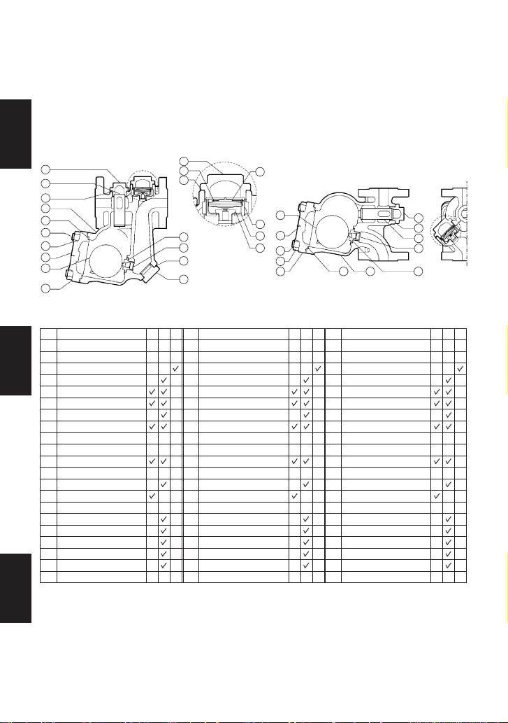
2. Configuration Aufbau Configuration
For horizontal installation
Für waagerechten Einbau
Pour installation horizontale
1
2
3
4
5
6
7
8
9
10
11
12
13
14
15
16
17
18
19
20
21
1
2
3
4
5
6
7
8
9
10
11
12
13
14
15
16
17
18
19
20
21
Body
Cover
Float
Orifice
Orifice Gasket
Orifice Plug Gasket*
Orifice Plug*
Cover Gasket
Cover Bolt
Cover Nut
Screen Holder Gasket
Screen Holder
Main Screen
X-element Cover Gasket
X-element Cover
Spring Clip
Air Vent (X-element)
Air Vent Valve Seat
X-element Guide
Air Vent Screen
Gehäuse
Gehäusedeckel
Schwimmerkugel
Ventilsitz
Ventilsitzdichtung
Ventilsitz-Stopfendichtung*
Ventilsitzstopfen*
Gehäusedichtung
Gehäuseschraube
Gehäusemutter
Haltestopfendichtung
Siebhaltestopfen
Gehäuseschmutzsieb
X-Elementgehäusedichtung
X-Elementgehäuse
Spannbügel
Entlüfter (X-Element)
Entlüfterventilsitz
X-Element-Führung
Entlüfter-Schmutzsieb
Corps
Couvercle
Flotteur
Orifice
Joint d'orifice
Joint de bouchon d'orifice*
Bouchon d'orifice*
Joint de couvercle
Boulon de couvercle
Écrou de couvercle
Joint porte-crépine
Porte-crépine
Crépine principale
Joint couvercle élément X
Couvercle élément X
Clip à ressort
Purge d'air (élément X)
Siège purge d'air
Guide élément X
Crépine purge d'air
Description Bauteil Désignation
M R F W R S E R FNo. Nr.
1
2
3
4
5
6
7
8
9
10
11
12
13
14
15
16
17
18
19
20
21
N°
For vertical installation
Für senkrechten Einbau
Pour installation verticale
* SJHNX only * Nur SJHNX * SJHNX uniquement
Erhältliche Ersatzteile:
(W) Wartungssatz,
(R) Reparatursatz,
(S) Schwimmerkugel
Jeux de pièces de rechange
disponibles :
(E) pièces d'entretien,
(R) pièces de réparation,
(F) flotteur
Replacement kits available:
(M) maintenance parts,
(R) repair parts,
(F) float
SJHX series
SJHX Serie
Gamme SJHX
SJHNX
SJHVX
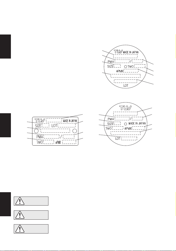
Nameplate Typenschild
Plaquette nominative
3
8 1 5
4
13
11
12
21
9
10
2
12
13
11
1
8
9
10
21
3
2
5
4
6
7
15
14
16 17
18
19
20
5
Deutsch
Français
English

Screw with Spring Washer Vis et rondelle de ressort
Schraube mit Federring
1
2
3
4
5
6
7
8
9
10
11
12
13
14
15
16
17
18
19
1
2
3
4
5
6
7
8
9
10
11
12
13
14
15
16
17
18
19
Body
Cover
Float
Orifice
Orifice Gasket
Orifice Plug Gasket*
Orifice Plug*
Cover Gasket
Cover Bolt
Cover Nut
Screen Holder Gasket
Screen Holder
Main Screen
Plug Cover Gasket
Plug Cover
Plug
Guide
Air Vent Strip (Bimetal)
Gehäuse
Gehäusedeckel
Schwimmerkugel
Ventilsitz
Ventilsitzdichtung
Ventilsitz-Stopfendichtung*
Ventilsitzstopfen*
Gehäusedichtung
Gehäuseschraube
Gehäusemutter
Haltestopfendichtung
Siebhaltestopfen
Gehäuseschmutzsieb
Gehäusedichtung
Stopfen-Gehäuse
Stopfen
Führung
Bimetallstreifen
Corps
Couvercle
Flotteur
Orifice
Joint d'orifice
Joint de bouchon d'orifice*
Bouchon d'orifice*
Joint de couvercle
Boulon de couvercle
Écrou de couvercle
Joint porte-crépine
Porte-crépine
Crépine principale
Joint couvercle
Couvercle de bouchon
Bouchon
Guide
Purge d'air (Bilame)
Description Bauteil Désignation
No. Nr.
1
2
3
4
5
6
7
8
9
10
11
12
13
14
15
16
17
18
19
N°
* SJHN only * Nur SJHN * SJHN uniquement
For horizontal installation
Für waagerechten Einbau
Pour installation horizontale
For vertical installation
Für senkrechten Einbau
Pour installation verticale
SJH series
SJH Serie
Gamme SJH
SJHN SJHV
20 Nameplate 20 Typenschild 20 Plaquette nominative
12
13
11
1
8
9
10
20
3
2
15
17
14
16
5
4
6
7
18
19
18
19
Contact TLV for availability of
replacement parts
Veuillez contacter TLV pour la
disponibilité de pièces de rechange
Zur Verfügbarkeit von Ersatzteilen
bitte TLV kontaktieren
3
20
9
10
2815
4
13
11
12 15
17
14
16
6
Deutsch
Français
English
Die Einbauhinweise beachten und die spezifizierten Betriebsgrenzen NICHT
ÜBERSCHREITEN. Nichtbeachtung kann zu Betriebsstörungen oder Unfällen führen.
Lokale Vorschriften können zur Unterschreitung der angegebenen Werte zwingen.
VORSICHT
Installer le produit correctement et NE PAS l’utiliser en dehors des plages
spécifiées. En cas de dépassement des limites données, des dysfonc-
tionnements ou accidents pourraient survenir. Il se peut que des règlements
locaux limitent l'utilisation du produit en deçà des spécifications indiquées.
ATTENTION
To avoid malfunctions, product damage, accidents or serious injury, install
properly and DO NOT use this product outside the specification range. Local
regulations may restrict the use of this product to below the conditions quoted.
CAUTION
3. Specifications Technische Daten Données techniques
Refer to the product nameplate for detailed specifications.
Die technischen Daten stehen auf dem Typenschild.
Les données techniques sont inscrites sur la plaquette nominative.
* Maximum allowable pressure (PMA) and maximum allowable temperature (TMA) are
PRESSURE SHELL DESIGN CONDITIONS, NOT OPERATING CONDITIONS.
** "Valve No." is displayed for products with options. This item is omitted from the
nameplate when there are no options.
* Maximal zulässiger Druck (PMA) und maximal zulässige Temperatur (TMA) sind
AUSLEGUNGSDATEN, NICHT BETRIEBSDATEN.
** Die „Valve No.“ wird angegeben bei Typen mit Optionen. Bei Typen ohne Optionen bleibt
diese Stelle frei.
* Pression maximale admissible (PMA) et température maximale admissible (TMA) sont les
CONDITIONS DE CONCEPTION, PAS LES CONDITIONS DE FONCTIONNEMENT.
** Le "Valve No." est indiqué pour des modèles avec options. Ce numéro ne figure pas sur les
modèles sans options.
G Production Lot No.
Fertigungslos-Nr.
Lot de production n°
H Valve No.**
C Maximum Allowable Pressure*
Maximal zulässiger Druck*
Pression maximale admissible*
F Maximum Operating Temperature
Maximale Betriebstemperatur
Température de fonctionnement maximale
D Maximum Allowable Temperature* TMA
Maximal zulässige Temperatur* TMA
Température maximale admissible* TMA
A Model
Typ
Modèle
E Maximum Differential Pressure
Maximaler Differenzdruck
Pression différentielle maximale
B Nominal Diameter
Größe/DN
Dimension/DN
SJH3NX / SJH3VX / SJH3N / SJH3V
SJH5NX / SJH5VX / SJH5N / SJH5V
SJH6NX / SJH6N
SJH7NX / SJH7VX / SJH7N / SJH7V
A
D
E
H
C
B
F
G
A
D
E
H
C
B
F
G
B
A
G
D
E
H
C
F
7
Deutsch
Français
English

4. Proper Installation
1. Before installation, be sure to remove all protective seals.
2. Before installing the trap, blow out the inlet piping to remove all dirt and oil.
3. Install the trap in the lowest part of the pipeline or equipment so the condensate flows
naturally downward into the trap by gravity. The inlet pipe should be as short and have as
few bends as possible.
4. Install the trap within the allowable inclination, as shown below. Also make sure that the
arrow mark on the body corresponds with the direction of flow.
5. When completing the piping, support the pipes properly within 800 mm (2.5 ft) on either side
of the trap.
6. Install a bypass valve to discharge condensate, and inlet and outlet valves to isolate the trap
in the event of trap failure or when performing maintenance.
7. Install a check valve at the trap outlet whenever the condensate discharge pipe leads to a
tank or recovery line, or whenever the condensate collection pipeline is connected with more
than one trap.
• Installation, inspection, maintenance, repairs, disassembly, adjustment
and valve opening/closing should be carried out only by trained
maintenance personnel.
• Take measures to prevent people from coming into direct contact with
product outlets.
• Use hoisting equipment for heavy objects.
• Install for use under conditions in which no freeze-up will occur.
• Install for use under conditions in which no water hammer will occur.
CAUTION
5˚
5˚
5˚
5˚
5˚
5˚
5˚
5˚
Maximum Allowable Inclination
Horizontal Model
Vertical Model
8
English

Check to make sure that the pipes connected to the trap have been installed properly.
1. Is the pipe diameter suitable?
2. Has the trap been installed within the allowable inclination and with the arrow on the body
pointing in the direction of flow?
3. Has sufficient space been secured for maintenance?
4. Have maintenance valves been installed at the inlet and outlet? If the outlet is subject to
back pressure, has a check valve been installed?
5. Is the inlet pipe as short as possible, with as few bends as possible, and installed so that the
condensate will flow naturally down into the trap?
6. Has the piping work been done correctly, as shown in the table below?
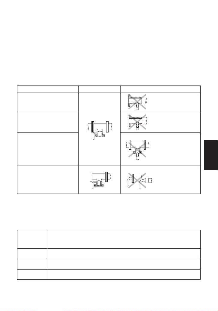
5. Piping Arrangement
Requirement
Diameter is too
small.
Diameter is too small
and inlet protrudes
into pipe.
Rust and scale
flow into the trap
with the condensate.
Condensate
collects in the
pipe.
Correct Incorrect
Install a catchpot of the
proper diameter.
Make sure the flow of
condensate is not
obstructed.
To prevent rust and scale
from flowing into the trap,
connect the inlet pipe
25 - 50 mm (1 - 2 in) above
the base of the T - pipe.
When installing on the blind
end, make sure nothing
obstructs the flow of
condensate.
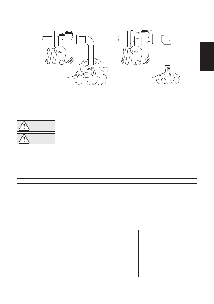
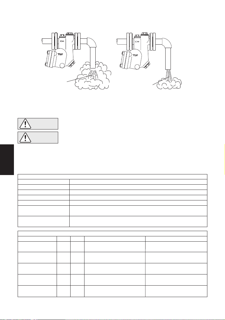
6. Operational Check
Normal: Condensate is discharged continuously with flash steam and the sound of
flow can be heard. If there is very little condensate, there is almost no
sound of flow.
Blocked: No condensate is discharged. The trap is quiet and makes no noise,
and the surface temperature of the trap is low.
Blowing: Live steam continually flows from the outlet and there is a continuous
metallic sound.
Live steam is discharged through the trap outlet together with the
condensate and there is a high-pitched sound.
A visual inspection can be carried out to aid in determining the necessity for immediate
maintenance or repair, if the trap is open to atmosphere. If the trap does not discharge to
atmosphere, use diagnostic equipment such as TLV TrapMan or TLV Pocket TrapMan (within its
pressure and temperature measuring range).
(When conducting a visual inspection, flash steam is sometimes mistaken for steam leakage. For
this reason, the use of a steam trap diagnostic instrument such as TLV TrapMan is highly
recommended.)
Steam
Leakage:
Continued on the next page
9
English
Operational inspections should be performed at least twice per year, or as called for by trap
operating conditions. Steam trap failure may result in temperature drop in the equipment, poor
product quality or losses due to steam leakage.
7. Inspection and Maintenance
WARNING
NEVER apply direct heat to the float. The float may explode due to
increased internal pressure, causing accidents leading to serious injury or
property and equipment damage.
• Installation, inspection, maintenance, repairs, disassembly, adjustment
and valve opening/closing should be carried out only by trained
maintenance personnel.
• Before attempting to open the trap, close the inlet and outlet isolation
valves and wait until the trap has cooled completely. Failure to do so
may result in burns.
• Be sure to use the proper components and NEVER attempt to modify
the product.
CAUTION
Body, Cover(s)
Gaskets
X-element (SJHX)
Screen(s)
Float
Air Vent Valve Seat (SJHX), Orifice
Air Vent Strip (SJH)
Check inside for damage, dirt, grease, oil film, rust or scale
Check for warping or damage
Check for damage
Check for clogging, corrosion or damage
Check for deformation, damage, oil film or water inside
Check for rust, scale, oil film, wear or damage
Avoid touching or distorting the air vent strip; unscrew it
only if damaged or if the orifice must be removed
Parts Inspection Procedure
Flash Steam
White jet
containing
water droplets
Live Steam Leakage
Clear, slightly
bluish jet
ReassemblyDisassembly
SJHX SJH
Disassembly/Reassembly (to reassemble, follow procedures in reverse)
Use a wrench to remove
Remove
Remove gasket and clean
sealing surfaces
Remove, being careful not to
scratch its polished surface
Coat threads with anti-seize and
tighten to the proper torque
Reattach with writing in the
proper orientation
Replace with a new gasket, do
not apply anti-seize
Insert into body, being careful not
to scratch its polished surface
Cover Nut 10
Cover 2
Cover Gasket 8
Float 3
Part & No.
Continued on the next page
◯ ◯
◯ ◯
◯ ◯
◯ ◯
"◯" indicates which models contain which parts
10
English

* SJHX only ** SJH only *** SJHNX, SJHN only
Note: Coat all threads with anti-seize
Model
Cover Nut 10
Orifice 4
X-element Cover 15*
Plug Cover 15**
Screen Holder 12
Air Vent Valve Seat 18*
Plug 16**
Orifice Plug 7***
Screw with Spring Washer 19**
Tightening Torque and Distance Across Flats
SJH3NX / SJH3N
SJH3VX / SJH3V
60
70
140
140
140
35
35
200
0.3
17
17
32
32
24
19
19
38
+
SJH5NX / SJH5N
SJH5VX / SJH5V
110
80
140
140
140
35
35
200
0.3
22
19
32
32
24
19
19
38
+
SJH6NX
SJH6N
130
200
140
140
400
35
35
400
0.3
22
30
32
32
50
19
19
50
+
SJH7NX / SJH7N
SJH7VX / SJH7V
mm
210
200
140
140
400
35
35
400
0.3
24
30
32
32
50
19
19
50
+
ReassemblyDisassembly
Screw with Spring
Washer 19
Air Vent Strip 18
Orifice Plug 7
Orifice Plug Gasket 6
Orifice 4
Orifice Gasket 5
Screen Holder 12
Screen Holder
Gasket 11
Main Screen 13
X-element Cover 15
Plug Cover 15
X-element Cover
Gasket 14
Plug Cover Gasket 14
Spring Clip 16
X-element 17
Air Vent Valve Seat 18
Plug 16
X-element Guide 19
Guide 17
Air Vent Screen 20
Remove with a Philips
screwdriver only if necessary
to remove the air vent strip
Remove without bending
only if necessary
Use a wrench to remove
Remove gasket and clean
sealing surfaces
Use a wrench to remove
Remove gasket and clean
sealing surfaces
Use a wrench to remove
Remove gasket and clean
sealing surfaces
Remove being careful not to
bend
Use a wrench to remove
Remove gasket and clean
sealing surfaces
Use appropriate pliers,
squeeze and remove
Remove from the guide
Use a wrench to remove
Remove without bending
Remove without bending
Tighten screw to the proper
torque
Carefully reattach without
bending
Coat threads with anti-seize
and tighten to the proper torque
Replace with a new gasket,
coat surfaces with anti-seize
Coat threads with anti-seize
and tighten to the proper torque
Replace with a new gasket, do
not coat surfaces with anti-seize
Coat threads with anti-seize
and tighten to the proper torque
Replace with a new gasket,
coat surfaces with anti-seize
Insert closed end first so the open
end is at the opening in the body
Coat threads with anti-seize
and tighten to the proper torque
Replace with a new gasket,
coat surfaces with anti-seize
Squeeze and insert securely
into the groove
Make sure the X-element is
not upside down
Coat threads with anti-seize
and tighten to the proper torque
Insert securely without bending
Insert securely without bending
Part & No.
SJHX
SJH
- ◯
- ◯
◯* ◯*
◯* ◯*
◯ ◯
◯ ◯
◯ ◯
◯ ◯
◯ ◯
◯ -
- ◯
- ◯
- ◯
◯ -
◯ -
◯ -
- ◯
◯ -
◯ -
◯ -
"◯" indicates which models contain which parts * SJHNX and SJHN only
N·m
mm
N·m
mm
N·m
mm
N·m
If drawings or other special documentation were supplied for the product, any torque given there
takes precedence over values shown here.
11
English
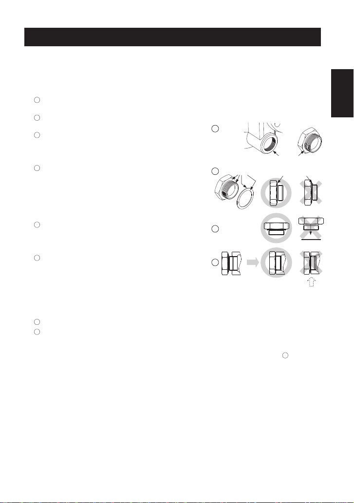
Instructions for Plug / Holder Disassembly and Reassembly
The seal on the threaded plugs/holders found on TLV products is formed by a flat metal
gasket. There are various installation orientations for the gaskets, such as horizontal,
diagonal and downward, and the gasket may be pinched in the thread recesses during
assembly.
Instructions for Disassembly and Reassembly
1Remove the plug/holder using a tool of the specified
size (distance across flats).
2The gasket should not be reused. Be sure to
replace it with a new gasket.
3Clean the gasket surfaces of the plug/holder and the
product body using a rag and/or cleaning agents, then
check to make sure the surfaces are not scratched or
deformed.
4Coat both the gasket surface of the plug/holder and
the threads of the plug/holder with anti-seize, then
press the gasket onto the center of the gasket
surface of the plug/holder, making sure the
anti-seize affixes the gasket tightly to the
plug/holder. Check to make sure the gasket is not
caught in the recesses of the threads.
5Hold the plug/holder upside down to make sure that
the anti-seize makes the gasket stick to the
plug/holder even when the plug/holder is held
upside down.
6Screw the plug/holder by hand into the product body
while making sure that the gasket remains tightly
affixed to the center of the gasket surface of the
plug/holder. Make sure the entire gasket is making
contact with the gasket surface of the product body.
It is important at this point to make sure the gasket
is not pinched in the thread recesses of the
plug/holder.
7Tighten the plug/holder to the proper torque.
8 Next, begin the supply of steam and check to make sure there is no leakage from the part
just tightened. If there is leakage, immediately close the inlet valve and, if there is a bypass
valve, take the necessary steps to release any residual pressure. After the surface of the
product cools to room temperature, repeat the procedure beginning from step 1.
3
5
6
Gasket
Do not pinch gasket
in thread recesses
4Coat with anti-seize
Gasket Surface
12
English
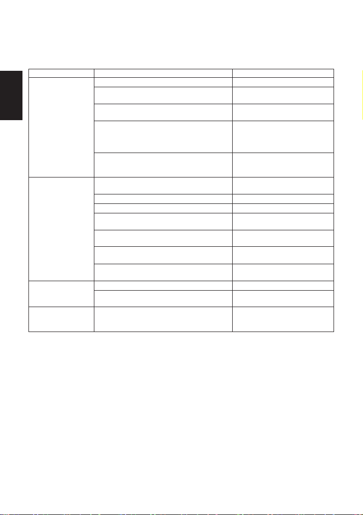
8. Troubleshooting
If the expected performance is unachievable after installation of the steam trap, read chapters 4
and 5 again and check the following points for appropriate corrective measures.
Problem Cause Remedy
Float is damaged or filled with condensate
Orifice, screen or piping is clogged with
rust or scale
X-element* or air vent strip** is damaged
The trap operating pressure exceeds the
maximum specified pressure, or there is
insufficient pressure differential between
the trap inlet and outlet
Steam-locking has occurred
Orifice is clogged, or rust and scale have
accumulated under the float
Orifice is damaged
Float is deformed or coated with scale
Trap is installed above the maximum
allowable inclination angle
Vibration of trap occurs
The X-element or air vent valve seat is
damaged, or clogged with rust or scale*
Air vent strip does not return to its proper
shape or is damaged**
Deterioration of or damage to gaskets
Improper tightening torque for cover was
used
Water hammer occurs
No condensate is
discharged
(blocked) or
discharge is poor
Steam is
discharged or
leaks from the trap
outlet
(blowing)
(steam leakage)
Steam leaks from a
place other than
the trap outlet
Float is frequently
damaged
Replace the float
Clean
Replace the X-element or air
vent strip
Compare specifications and
actual operating conditions
Blow down through the bypass
or close the trap inlet valve
and allow the trap to cool
Clean
Replace the orifice
Clean or replace the float
Correct the installation
Lengthen inlet piping, then
fasten it securely
Clean or replace the X-element
or air vent valve seat
Replace with new air vent strip
Replace the gaskets
Tighten to the proper torque
Examine the piping for
problems that can cause water
hammer
* SJHX only ** SJH only
13
English
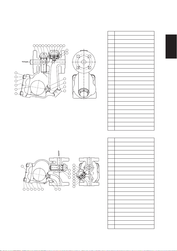
9.1 Configuration
9. Option (Integral Plate-type Bimetal Air Vent Unit)
SJH3NB/SJH5NB/SJH6NB/SJH7NB
SJH3VB/SJH5VB/SJH7VB
NameNo.
Body
Cover
Float
Orifice
Orifice Gasket
Orifice Plug Gasket
Orifice Plug
Cover Gasket
Cover Bolt
Cover Nut
Screen Holder Gasket
Screen Holder
Main Screen
Element Cover Gasket
Element Cover
Element Guide
Air Vent Valve Seat
Bimetal Plate
Snap Ring
Air Vent Valve
Spring Clip
Air Vent Screen
Nameplate
1
2
3
4
5
6
7
8
9
10
11
12
13
14
15
16
17
18
19
20
21
22
23
NameNo.
Body
Cover
Float
Orifice
Orifice Gasket
Element Cover
Element Cover Gasket
Cover Gasket
Cover Nut
Cover Bolt
Screen Holder
Screen Holder Gasket
Screen
Element Guide
Air Vent Valve Seat
Bimetal Plate
Snap Ring
Air Vent Valve
Spring Clip
Air Vent Screen
Nameplate
1
2
3
4
5
6
7
8
9
10
11
12
13
14
15
16
17
18
19
20
21
NOTE: Installation and maintenance of the product is identical to the SJHNX/VX type.
23
10
11
8
9
3
2
5
4
6
22
112 13
7
14 1915 21 20 18 17
16
10
11
254
6
1
13
7
14
19
21
20
18
16
15
17
12
89 3
English
14

Use the following procedures to remove components. Use the same procedures in reverse to
reassemble.
(Installation, inspection, maintenance, repairs, disassembly, adjustment and valve
opening/closing should be carried out only by trained maintenance personnel.)
NOTE: This section explains disassembling and reassembling of the bimetal unit only. For other
parts, refer to page 10 to page 11.
9.2 Disassembly/Reassembly
CAUTION When disassembling or removing the product, wait until the internal
pressure equals atmospheric pressure and the surface of the product
has cooled to room temperature. Disassembling or removing the product
when it is hot or under pressure may lead to discharge of fluids, causing
burns, other injuries or damage.
WARNING
NEVER apply direct heat to the float. The float may explode due to
increased internal pressure, causing accidents leading to serious injury or
damage to property and equipment.
CAUTION Use hoisting equipment for heavy objects (weighing approximately 20 kg
(44 lb) or more). Failure to do so may result in back strain or other injury if
the object should fall.
Disassembly/Reassembly of the Bimetal Section
ReassemblyPart Disassembly
Element Cover Consult the table of
tightening torques and
tighten to the proper
torque
Remove with a
socket wrench
Element Cover
Gasket Replace with a new
gasket
Remove the gasket
and clean sealing
surfaces
Spring Clip Insert it securely into
the groove
Pinch the insides
together and
remove from the
element guide
Bimetal Unit Insert the bimetal unit
into the element guide
with "T" mark on the
bimetal facing towards
the air vent valve seat.
-
Air Vent Valve
Seat
(for Bimetal)
Consult the table of
tightening torques and
tighten to the proper
torque
Remove with a
socket wrench
Spring Clip
Bimetal Unit
Air Vent Valve
Seat
Element Guide
English
15

Table of Tightening Torques
NOTE: Only for parts related to the bimetal unit. (For other parts, refer to page 11.)
NOTE: - Coat all threaded portions with anti-seize.
- If drawings or other special documentation were supplied for
the product, any torque given there takes precedence over
values shown here.
Torque
N·m
Distance Across
Flats
mm
Model
Torque
N·m
Distance Across
Flats
mm
35 19140 32
SJH3NB
SJH5NB
SJH6NB
SJH7NB
SJH3VB
SJH5VB
SJH7VB
Part Element Cover Air Vent Valve Seat
(1 N·m ≈10 kg·cm)
10. Product Warranty
1) Warranty Period: one year after product delivery.
2) TLV CO., LTD. warrants this product to the original purchaser to be free from defective
materials and workmanship. Under this warranty, the product will be repaired or replaced at
our option, without charge for parts or labor.
3) This product warranty will not apply to cosmetic defects, nor to any product whose exterior
has been damaged or defaced; nor does it apply in the following cases:
1. Malfunction due to improper installation, use, handling, etc., by other than TLV CO., LTD.
authorized service representatives.
2. Malfunctions due to dirt, scale, rust, etc.
3. Malfunctions due to improper disassembly and reassembly, or inadequate inspection and
maintenance by other than TLV CO., LTD. authorized service representatives.
4. Malfunction due to disasters or forces of nature.
5. Accidents or malfunctions due to any other cause beyond the control of TLV CO., LTD.
4) Under no circumstances will TLV CO., LTD. be liable for consequential economic loss or
damage or consequential damage to property.
English
16

4. Einbauhinweise
1. Vor dem Einbau die Transport-Schutzkappen entfernen.
2. Vor Einbau Leitung durchblasen, um Öl und Verschmutzungen zu entfernen.
3. Die Zuführleitung sollte kurz sein, so wenig Krümmer wie möglich aufweisen und ist so zu
verlegen, dass das Kondensat durch Schwerkraftwirkung dem Kondensatableiter zufließen
kann.
4. Der Kondensatableiter ist so einzubauen, dass die nachfolgend gezeigten
Schräglagentoleranzen nicht überschritten werden und der Pfeil auf dem Gehäuse in
Durchflussrichtung zeigt.
5. Die Kondensatleitung muss im Abstand von maximal 800 mm vor und hinter dem
Kondensatableiter abgestützt werden.
6. Um Wartung und Inspektion zu erleichtern, wird der Einbau von Absperrorganen vor und
hinter dem Kondensatableiter empfohlen. Auch sollte eine Umgehungsleitung zur
Notentwässerung vorgesehen werden.
7. Falls die Auslassleitung in einen Tank oder eine Kondensatrückführleitung mündet, oder falls
mehrere Kondensatableiter an eine gemeinsame Leitung angeschlossen sind, muss ein
Rückschlagventil hinter jedem Kondensatableiter eingebaut werden.
• Einbau und Ausbau, Inspektion, Wartungs- und Reparaturarbeiten,
Öffnen/Schließen von Armaturen, Einstellung von Komponenten dürfen
nur von geschultem Wartungspersonal vorgenommen werden.
• In sicherer Enfernung von Auslassöffnungen aufhalten und andere
Personen warnen, sich fernzuhalten.
• Für schwere Werkstücke müssen geeignete Hebezeuge verwendet
werden.
• Kondensatableiter in frostsicherer Umgebung einbauen, oder
entsprechende Frostschutzeinrichtungen vorsehen.
• Kondensatableiter nur an Stellen einbauen, an denen kein Wasserschlag
eintreten kann.
VORSICHT
5˚
5˚
5˚
5˚
Schräglagentoleranz
Horizontaler Typ
Vertikaler Typ
5˚
5˚
5˚
5˚
17
Deutsch
Stellen Sie sicher, dass die Rohrleitungsarbeiten richtig ausgeführt wurden und dass der
Kondensatableiter wie beschrieben, eingebaut wurde.
1. Ist die Nennweite groß genug?
2. Wurde der Kondensatableiter horizontal, bzw. innerhalb der Schräglagentoleranz und mit
dem Pfeil in Durchflussrichtung eingebaut?
3. Ist genügend Platz für Wartungsarbeiten vorhanden?
4. Wurden vor und hinter dem Kondensatableiter Absperrarmaturen eingebaut? Falls
Gegendruck besteht, wurde ein Rückschlagventil eingebaut?
5. Ist die Zuleitung so kurz wie möglich, hat sie so wenig Krümmer wie möglich und kann das
Kondensat durch Schwerkraft zufließen?
6. Wurden die Rohrleitungen so ausgeführt, wie unten beschrieben?
5. Rohrleitungsführung
Vorschrift
Durchmesser zu klein.
Durchmesser zu klein
und Abflussrohr ragt in
Rohrleitung hinein.
Rost und sonstige
Ablagerungen gelangen
mit dem Kondensat in
den Kondensatableiter.
Kondensat sammelt
sich in Rohrleitung an.
Richtig Falsch
Kondensatstutzen mit
ausreichendem Durchmesser
einbauen.
Für ungehinderten
Kondensatzufluss sorgen.
Um Rost und sonstige Ab-
lagerungen vom Kondensatab-
leiter fernzuhalten muss die
Zuleitung 25-50 mm über dem
Deckel des Stutzens
angeschlossen werden.
Bei Einbau an Leitungsenden
ist die nebenstehende
Anschlussart vorzusehen,
damit das Kondensat
ungehindert abfließen kann.
6. Funktionsprüfung
Normal: Kondensat wird kontinuierlich unter Bildung von Entspannungsdampf
abgeleitet. Ein entsprechendes Fließgeräusch ist zu hören. Bei geringer
Kondensatmenge ist dieses Geräusch ebenfalls geringer, oder kaum noch
wahrnehmbar.
Blockiert:
KA bläst:
Dampfverlust:
Blockiert: Kondensatabfluss nicht feststellbar. Der KA macht kein Geräusch und seine
Oberflächentemperatur ist niedrig.
KA bläst: Sattdampf tritt kontinuierlich an der Auslassseite aus und ein metallisch
klingendes Geräusch ist hörbar.
Dampfverlust: Sattdampf, vermischt mit Kondensat tritt mit einem pfeifenden Geräusch
an der Auslassseite aus.
Falls der Kondensatableiter das Kondensat ins Freie abführt, können visuelle Inspektionen einen
Hinweis geben, ob sofortige Wartung oder Reparatur notwendig ist. An Kondensatrückführ-
leitungen angeschlossene Kondensatableiter können mit geeigneten Messgeräten, z. B. TLV
Pocket TrapMan oder TLV TrapMan (innerhalb ihrer Messwertgrenzen) geprüft werden.
(Bei visueller Inspektion wird oft Entspannungsdampf mit Dampfverlust verwechselt. Daher wird
empfohlen, im Zweifel Messgeräte, z. B. TLV TrapMan zu verwenden.)
Normal: Kondensat wird kontinuierlich unter Bildung von Entspannungsdampf
abgeleitet. Ein entsprechendes Fließgeräusch ist zu hören. Bei geringer
Kondensatmenge ist dieses Geräusch ebenfalls geringer, oder kaum noch
wahrnehmbar.
Fortsetzung auf der nächsten Seite
18
Deutsch
Gehäuse, Deckel
Dichtungen
X-Element (SJHX)
Schmutzsiebe
Schwimmerkugel
Entlüfterventilsitz (SJHX),
Ventilsitz
Bimetallstreifen (SJH)
Auf Ablagerungen, Rost, Schmutz, Ölfilm prüfen
Auf Verformung oder Beschädigung prüfen
Auf Beschädigung prüfen
Auf Verstopfung, Ablagerungen, Beschädigung prüfen
Auf Verformung, Beschädigung oder Wasser in der Kugel prüfen
Auf Ablagerungen, Rost, Schmutz, Ölfilm prüfen
Bimetallstreifen nicht verbiegen. Nur abschrauben wenn er
beschädigt ist, oder wenn der Ventilsitz abgenommen werden muss
Überprüfung der Einzelteile
Entspannungsdampf
Weißer
Strahl mit
Wassertröpfchen
Dampfverlust
Klarer, leicht
bläulicher Strahl
Es wird empfohlen, mindestens zweimal pro Jahr oder, je nach Betriebsweise, in kürzeren
Zeitabständen eine Inspektion durchzuführen.
7. Inspektion und Wartung
WARNUNG
Um Unfälle und Verletzungen zu vermeiden, darf die Schwimmerkugel
NICHT ERHITZT WERDEN, da sie infolge erhöhten Innendrucks platzen
kann.
• Einbau und Ausbau, Inspektion, Wartungs- und Reparaturarbeiten,
Öffnen/Schließen von Armaturen, Einstellung von Komponenten dürfen nur
von geschultem Wartungspersonal vorgenommen werden.
• Vor dem Öffnen des Kondensatableiters sind die Absperrarmaturen auf
beiden Seiten zu schließen. Gehäuse auf Raumtemperatur abkühlen
lassen. Nichtbeachtung kann zu Verbrennungen führen.
• Zur Reparatur nur Original-Ersatzteile verwenden und NICHT
VERSUCHEN, das Produkt zu verändern.
VORSICHT
EinbauAusbauSJHX SJH
Ausbau und Einbau der Teile (Einbau erfolgt in umgekehrter Reihenfolge)
Gabel- oder Steckschlüssel
verwenden
Abheben
Dichtung abnehmen,
Dichtflächen reinigen
Herausnehmen, feingeschliffene
Oberfläche nicht zerkratzen
Nur abschrauben falls Bimetall-
streifen ersetzt werden muss
Mit Schmiermittel bestreichen,
Anzugsmoment beachten
Deckel so ausrichten dass das
Typenschild lesbar ist
Dichtung erneuern, nicht mit
Schmiermittel bestreichen
Einsetzen, feingeschiffene
Oberfläche nicht zerkratzen
Einschrauben, Anzugsmoment
beachten
Gehäusemutter 10
Gehäusedeckel 2
Gehäusedichtung 8
Schwimmerkugel 3
Schraube mit
Federring 19
Bauteil & Nr.
Fortsetzung auf der nächsten Seite
◯ ◯
◯ ◯
◯
◯◯
-
◯
◯
Die für die jeweiligen Typen zutreffenden Bauteile sind mit „◯“ bezeichnet
19
Deutsch
This manual suits for next models
15
Table of contents
Languages:
Other TLV Water Filtration System manuals


