Filters itm FL Series User manual
www.itmfilters.com
Metallic manual filters
User manual
FL / FY / FL-PP / FY-EC
Serial number:
_________________
Purchase date:
_________________
YFILTER (FY)
LFILTER PIVOT FOOT
(FL-PP)
YFILTER
CYCLONIC EFFECT (FY-EC)
LFILTER (FL)

www.itmfilters.com
Index
User Manual FY/FL/FL-PP/FY-EC
Introduction ...................................................................................................................... 1
1.1 Filter identification.................................................................................................... 1
1.2 Basic concepts ........................................................................................................... 1
Data Sheet......................................................................................................................... 2
2.1 Metallic L Filter (FL-M) .............................................................................................. 2
2.2 Metallic Y Filter (FY-M).............................................................................................. 3
2.3 L Filter - Metallic Pivot Foot (FL-PPM)....................................................................... 4
2.4 Y Filter - Metallic Cyclonic Effect (FY-EC)................................................................... 4
2.5 Y Filter - Cyclonic Effect –Flow rates as a function of plugged orifices.................... 5
2.6 Manufacturing technical characteristics ................................................................... 7
Installation......................................................................................................................... 7
Operation and maintenance ............................................................................................. 7
Spare parts ........................................................................................................................ 8
5.1 Exploded view Metallic Y Filter (FY-M)...................................................................... 8
5.2 Exploded view Metallic L Filter (FL-M) ...................................................................... 9
5.3 Exploded view L Filter –Metallic Pivot Foot (FL-PPM)............................................ 10
5.4 Exploded view Y Filter –Cyclonic Effect (FY-EC)...................................................... 11
Product warranty ............................................................................................................ 12
USER MANUAL FY /FL /FL-PP /FY-EC
www.itmfilters.com
Introduction
First of all, we want to thank you for purchasing this filter, the result of the work of a group of
people committed to offering the correct solution to each filtration process. All products
designed and manufactured by ITM Filters meet self-imposed requirements for quality,
efficiency and durability. This philosophy is accredited through certification by external bodies.
The highest efficiency of the system is obtained with correct operation and maintenance, please
properly follow the indications in this manual throughout the life of the product. We invite you
to visit our website: www.itmfilters.com for more information about our products and our
company policies.
1.1 Filter identification
The filter is identified with the following decal:
1.2 Basic concepts
Filtration surface: Area that allows water to pass while retaining suspended particles.
Recommended flow rate: The optimal filtration must take into account the quality of the source
water and the application it has. The application of water is divided into 2 sectors, which have
maximum theoretical flows. The sectorization corresponds to the type of irrigation:
●Sector 1: Drip irrigation - Mesh 125 µm.
●Sector 2: Sprinkler irrigation - Mesh ø2 mm.
Loss of pressure (HEAD LOSS): It is the difference in load produced between two points of the
same flow. The friction of the water with the filter medium produces a loss of energy. The diluted
substances are trapped in the mesh generating a decrease in the porosity of the filter medium,
which causes an increase in the pressure drop.
The pressure drop measurement is carried out by means of a pressure tap on the inlet manifold
and another one on the outlet manifold.
USER MANUAL FY /FL /FL-PP /FY-EC
1
IMAGE 1
www.itmfilters.com
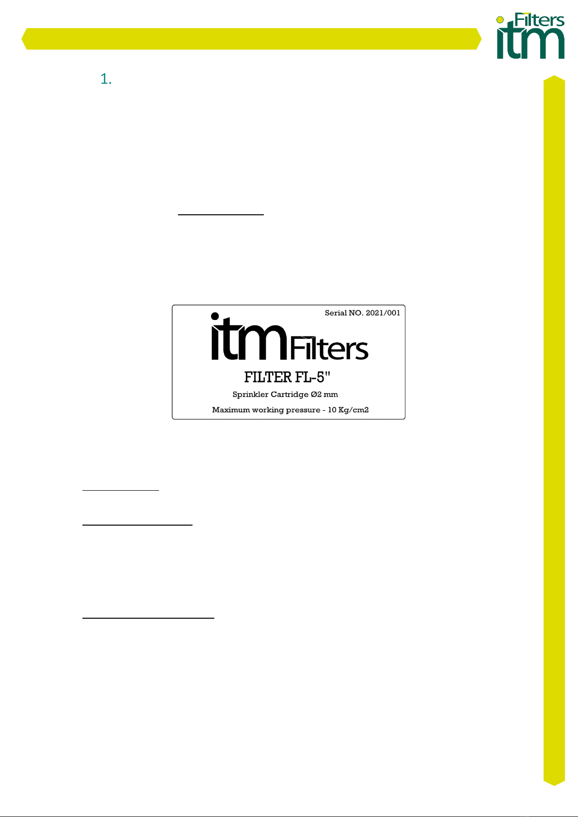
Data Sheet
2.1 Metallic L Filter (FL-M)
MODEL
ØI/ØO
Flows (m³/h)
Filtration
Surface
(cm²)
Net
Weight
(kg)
Filter opening
Dimensions (mm)
Mesh Cartridge
(Drip)
ø2 mm
Cartridge
(Sprinkler)
ØD
L
H
W
FL-2"-M
Male
Thread 2"
21
26
1500
12
Wing Nut
165
350
605
140
FL-3"-M
Flange 3"
42
51
2006
20
Wing Nut
165
365
746
145
FL-4"-165-M
Flange 4"
83
97
3007
24
Wing Nut
165
500
1025
150
FL-4"-220-M
Flange 4"
104
121
3160
33
Screws
220
500
797
175
FL-5"-M
Flange 5"
128
155
3160
36
Screws
220
500
797
175
FL-6"-M
Flange 6"
152
185
5579
63
Screws
323
840
1086
265
TABLE 1
USER MANUAL FY /FL /FL-PP /FY-EC
2
Water inlet
Working pressure = 10 kg/cm²*
Water inlet
CHART 1
CHART 2
IMAGE 2
Flow (m3/h)
Flow (m3/h)
Pressure loss - Kg/cm2
Pressure loss - Kg/cm2
FL-M load loss, 125 microns pass
FL-M load loss Ø2 mm pass
*Ask about other pressures

www.itmfilters.com
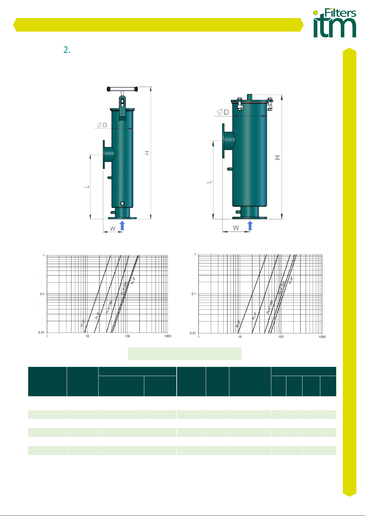
2.2 Metallic Y Filter (FY-M)
MODEL
ØI/ØO
Flows (m³/h)
Filtration
Surface
(cm²)
Net
Weight
(kg)
Filter opening
Dimensions (mm)
Mesh Cartridge
(Drip)
ø2 mm
Cartridge
(Sprinkler)
ØD
L
H
W
FY-2"-M
Male
Thread 2"
21
26
1500
12
Wing Nut
165
450
470
613
FY-3"-M
Flange 3"
42
51
2006
21
Wing Nut
165
495
542
757
FY-4"-165-M
Flange 4"
83
97
3007
25
Wing Nut
165
695
678
1096
FY-4"-220-M
Flange 4"
104
121
3160
36
Screws
220
695
580
801
FY-5"-M
Flange 5"
128
155
3160
38
Screws
220
695
595
801
FY-6"-M
Flange 6"
152
185
5579
66
Screws
323
725
924
990
FY-8"-M
Flange 8"
301
365
11040
135
Screws
355
1000
1137
1323
FY-10"-M
Flange
10"
402
485
13700
163
Screws
355
1000
1356
1515
TABLE 2
Water
inlet
Water
inlet
Working pressure = 10 kg/cm²*
USER MANUAL FY /FL /FL-PP /FY-EC
3
CHART 3
CHART 4
IMAGE 3
Flow (m3/h)
Flow (m3/h)
Pressure loss - Kg/cm2
Pressure loss- Kg/cm2
FY-M load loss, 125 microns pass
FY-M load loss, Ø2 mm pass
*Ask about other pressures

www.itmfilters.com
2.3 L Filter - Metallic Pivot Foot (FL-PPM)
MODEL
ØI/ØO
Flow (m³/h)
Filtration
Surface
(cm²)
Net
Weight
(kg)
Filter
opening
Dimensions (mm)
ø2 mm Cartridge
(Sprinkler)
ØD
L
H
W
FL-PPM-6"
Flange 6"
285
8550
94
Flange
323
1415
1690
265
FL-PPM-8"
Flange 8"
340
11350
112
Flange
323
1640
1940
265
FL-PPM-10"
Flange 10"
515
15630
176
Flange
406
1610
1934
300
FL-PPM-12"
Flange 12"
605
18000
199
Flange
406
1800
2257
300
TABLE 3
2.4 Y Filter - Metallic Cyclonic Effect (FY-EC)
MODEL
ØI/ØO
Flow (m³/h)
Filtration
Surface
(cm²)
Net
Weight
(kg)
Filter opening
Dimensions (mm)
Mesh Cartridge
(Drip)
ØD
L
H
W
FY-EC-2"-M
Male Thread 2"
39
1500
12
Wing Nut
165
450
503
672
FY-EC-3"-M
Flange 3"
57
2006
21
Wing Nut
165
495
577
830
FY-EC-4"-M
Flange 4"
66
3160
38
Screws
220
695
710
1139
FY-EC-5"-M
Flange 5"
66
3160
39
Screws
220
695
685
1005
FY-EC-6"-M
Flange 6"
120
5579
66
Screws
323
725
924
990
TABLE 4
Working pressure = 10 kg/cm²*
USER MANUAL FY /FL /FL-PP /FY-EC
4
Water
inlet
Working pressure = 10 kg/cm²*
*Ask about other pressures
Water
inlet
Water
inlet
IMAGE 5
IMAGE 4
*Ask about other pressures

www.itmfilters.com
2.5 Y Filter - Cyclonic Effect –Flow rates as a function of plugged orifices
•Flows FY-2’’ – CIC Differential pressure 0,5 kg/cm²
10 PLUGS
Q = 26.8 m³/h
11 PLUGS
Q = 21.6 m³/h
12 PLUGS
Q = 18.5 m³/h
13 PLUGS
Q = 14.7 m³/h
14 PLUGS
Q = 12 m³/h
15 PLUGS
Q = 8.5 m³/h
16 PLUGS
Q = 6 m³/h
17 PLUGS
Q = 2.5 m³/h
TABLE 5
•Flows FY-3’’ – CIC Differential pressure 0,5 kg/cm²
0 PLUGS
Q = 52.5m³/h
1 PLUGS
Q = 50.5 m³/h
2 PLUGS
Q = 49 m³/h
3 PLUGS
Q = 46.8 m³/h
4 PLUGS
Q = 42.9 m³/h
5 PLUGS
Q = 40.3 m³/h
6 PLUGS
Q = 36.6 m³/h
7 PLUGS
Q = 34.2 m³/h
8 PLUGS
Q = 30.7 m³/h
9 PLUGS
Q = 28.5 m³/h
TABLE 6
USER MANUAL FY /FL /FL-PP /FY-EC
5

www.itmfilters.com
•Flows FY-4’’ and FY-5’’– CIC Differential pressure 0,5 kg/cm²
0 PLUGS
Q=65m³/h
1 PLUGS
Q=63m³/h
2 PLUGS
Q=60m³/h
3 PLUGS
Q=56.8m³/h
4 PLUGS
Q=54.3m³/h
5 PLUGS
Q=51.5m³/h
6 PLUGS
Q=49m³/h
7 PLUGS
Q=46.5m³/h
8 PLUGS
Q=43.4m³/h
9 PLUGS
Q=41.3m³/h
10 PLUGS
Q=39m³/h
11 PLUGS
Q=36m³/h
12 PLUGS
Q=33.8m³/h
TABLE 7
•Flows FY-6’’ – CIC Differential pressure 0,5 kg/cm²
0 PLUGS
Q=112m³/h
1 PLUGS
Q=107m³/h
2 PLUGS
Q=103.5m³/h
3 PLUGS
Q=101m³/h
4 PLUGS
Q=98m³/h
5 PLUGS
Q=94.8m³/h
6 PLUGS
Q=92m³/h
7 PLUGS
Q=90m³/h
8 PLUGS
Q=86.3m³/h
9 PLUGS
Q=83.8m³/h
10 PLUGS
Q=80.9m³/h
11 PLUGS
Q=77.3m³/h
12 PLUGS
Q=75.8m³/h
13 PLUGS
Q=72.9m³/h
14 PLUGS
Q=70m³/h
15 PLUGS
Q=68.9m³/h
16 PLUGS
Q=66.5m³/h
17 PLUGS
Q=63.8m³/h
18 PLUGS
Q=61.5m³/h
19 PLUGS
Q=58.5m³/h
20 PLUGS
Q=57m³/h
21 PLUGS
Q=54m³/h
22 PLUGS
Q=51.8m³/h
23 PLUGS
Q=49m³/h
TABLE 8
USER MANUAL FY /FL /FL-PP /FY-EC
6

www.itmfilters.com
2.6 Manufacturing technical characteristics
-Materials:
oCarbon steel metal components.
oZinc plated screws 6.8.
oMesh cartridge : PVC structure with AISI-316 Stainless Steel. Filtration degree:
125 microns.
oGrinding cartridge: AISI-304 Stainless Steel. Ø2 mm pass.
oEDPM gaskets: 60 SHORE.
-Superficial treatment:
oSurface shot blasting up to SA ½ grade.
oTwo-layer EPOXY-POLYESTER powder paint finish, oven-polymerized RAL 6004.
-Working characteristics:
oMaximum operating temperature 50ºC.
Installation
1. Make sure the filter flow direction is correct.
2. Place the inlet and outlet manifolds, fixing the flanges with their corresponding gaskets.
3. Place the pressure gauges, one on the inlet manifold and the other on the water outlet
manifold.
4. Carry out a first manual cleaning of the filter mesh.
5. Check that the unions are tight, turn on the water supply and verify that there are no leaks.
6. Filtering. Open the water flow at the recommended flow rate and at a working pressure of
10 kg/cm².
7. Clean the filter when the pressure gauges indicate a pressure difference equal to or greater
than 0.5 kg/cm².
8. Cleaning. Disconnect the water flow and open the filter, depending on the model, by
loosening the handle or the Screws. Remove the cap and then the filter, clean it by applying
high pressure water to its outer surface and use a bristle brush on the inside if necessary.
Replace and close the filter ensuring that the cap fits tightly
Operation and maintenance
Mesh filtering consists in the physical separation between water and the substances that are
suspended in it. When the mesh filter becomes clogged, it produces a pressure difference
between the water inlet and outlet. The manual cleaning cycle is necessary when reaching a
pressure difference of 0,5 kg/cm². The water passes from the internal area of the filter to the
external one causing the accumulation of dirt in the internal part of the mesh.
Maintenance necessary for proper operation: review of joints and review of paint.
USER MANUAL FY /FL /FL-PP /FY-EC
7
www.itmfilters.com
Spare parts
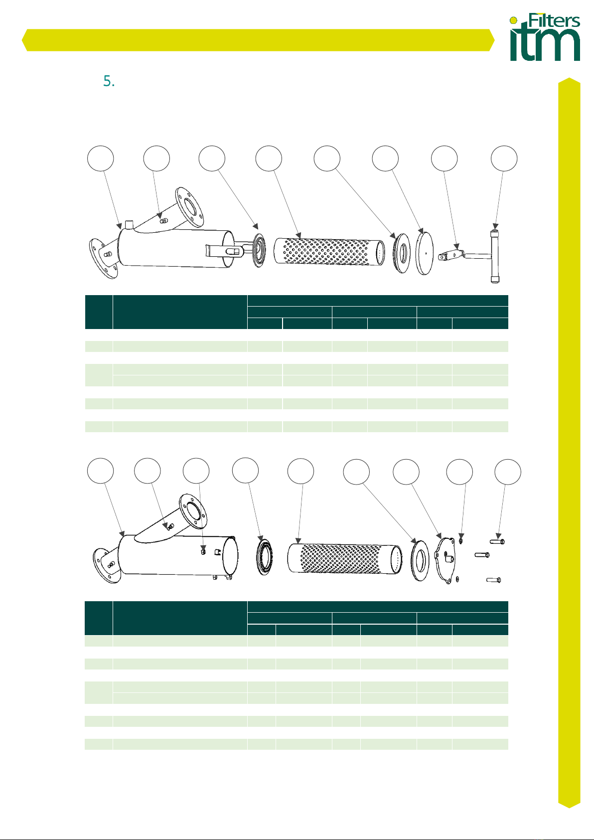
5.1 Exploded view Metallic Y Filter (FY-M)
Nº
DENOMINATION
FY MODELS
FY2
FY3
FY4-165
U.
Code
U.
Code
U.
Code
1
Body
1
FY-2-02
1
FY-3-02
1
FY-4-165-02
2
Plug
2
-
2
-
2
-
3
Lower Gasket
1
FY-2-08
1
FY-2-08
1
FY-2-08
4
Mesh Cartridge-Drip
1
FY-2-04
1
FY-3-04
1
FY-3-165-04
Cartridge ø2 - Sprinkler
1
FY-2-03
1
FY-3-03
1
FY-3-165-03
5
Upper Gasket
1
FY-2-09
1
FY-2-09
1
FY-2-09
6
Cap
1
FY-2-05
1
FY-2-05
1
FY-2-05
7
Crossbar
1
FY-2-07
1
FY-2-07
1
FY-2-07
8
Wing Nut
1
FY-2-06
1
FY-2-06
1
FY-2-06
TABLE 9
Nº
DENOMINATION
FY MODELS
FY4-220
FY5
FY6
U.
Code
U.
Code
U.
Code
1
Body
1
FY-4-220-02
1
FY-5-02
1
FY-6-02
2
Plug
2
-
2
-
2
-
3
Hex nut. M16
3
DIN934
3
DIN934
6
DIN934
4
Lower Gasket
1
FY-4-220-08
1
FY-4-220-08
1
FY-6-08
5
Mesh Cartridge-Drip
1
FY-4-220-04
1
FY-5-04
1
FY-6-04
Cartridge ø2 -Sprinkler
1
FY-4-220-03
1
FY-5-03
1
FY-6-03
6
Upper gasket
1
FY-4-220-09
1
FY-4-220-09
1
FY-6-09
7
Cap
1
FY-4-220-05
1
FY-4-220-05
1
FY-6-05
8
Flat washer D16
3
DIN125
3
DIN125
6
DIN125
9
Hex screw. M16
3
DIN933
3
DIN933
6
DIN933
TABLE 10
1
2
3
4
5
6
7
8
1
2
3
4
5
7
8
9
6
USER MANUAL FY /FL /FL-PP /FY-EC
8
www.itmfilters.com
5.2 Exploded view Metallic L Filter (FL-M)
Nº
DENOMINATION
FL MODELS
FL2
FL3
FYL-4-165
U.
Code
U.
Code
U.
Code
1
Body
1
FL-2-02
1
FL-3-02
1
FL-4-165-02
2
Plug
2
-
2
-
2
-
3
Lower Gasket
1
FY-2-08
1
FY-2-08
1
FY-2-08
4
Mesh Cartridge-Drip
1
FY-2-04
1
FY-3-04
1
FY-4-165-04
Cartridge ø2 -Sprinkler
1
FY-2-03
1
FY-3-03
1
FY-4-165-03
5
Upper gasket
1
FY-2-09
1
FY-2-09
1
FY-2-09
6
Cap
1
FY-2-05
1
FY-2-05
1
FY-2-05
7
Crossbar
1
FY-2-07
1
FY-2-07
1
FY-2-07
8
Wing Nut
1
FY-2-06
1
FY-2-06
1
FY-2-06
TABLE 11
Nº
DENOMINATION
FL MODELS
FL4-220
FL5
FL6
U.
Code
U.
Code
U.
Code
1
Body
1
FL-4-220-02
1
FL-5-02
1
FL-6-02
2
Plug
2
-
2
-
2
-
3
Hex nut. M16
3
DIN934
3
DIN934
6
DIN934
4
Lower Gasket
1
FY-4-220-08
1
FY-4-220-08
1
FY-6-08
5
Mesh Cartridge-Drip
1
FY-4-220-04
1
FY-5-04
1
FY-6-04
Cartridge ø2 -Sprinkler
1
FY-4-220-03
1
FY-5-03
1
FY-6-03
6
Upper gasket
1
FY-4-220-09
1
FY-4-220-09
1
FY-6-09
7
Cap
1
FY-4-220-05
1
FY-4-220-05
1
FY-6-05
8
Flat washer D16
3
DIN125
3
DIN125
6
DIN125
9
Hex screw. M16
3
DIN933
3
DIN933
6
DIN933
TABLE 12
1
2
3
4
5
6
7
8
1
2
3
4
5
7
8
9
6
USER MANUAL FY /FL /FL-PP /FY-EC
9
www.itmfilters.com
5.3 Exploded view L Filter –Metallic Pivot Foot (FL-PPM)
Nº
DENOMINATION
FL-PPM MODELS
FL-PPM-6
FL-PPM-8
FL-PPM-10
FL-PPM-12
U.
Code
U.
Code
U.
Code
U.
Code
1
Body
1
FL-PPM-6-02
1
FL-PPM-8-02
1
FL-PPM-10-02
1
FL-PPM-12-02
2
Plug
2
-
2
-
2
-
2
-
3
Hex nut. M16
3
DIN934
3
DIN934
6
DIN934
6
DIN934
4
Lower Gasket
1
FY-PPM-6-08
1
FL-PPM-6-08
1
FL-PPM-10-08
1
FL-PPM-10-08
5
Mesh Cartridge-Drip
1
FY-PPM-6-04
1
FL-PPM-8-04
1
FL-PPM-10-04
1
FL-PPM-12-04
Cartridge ø2 -Sprinkler
1
FY-PPM-6-03
1
FL-PPM-8-03
1
FL-PPM-10-03
1
FL-PPM-12-03
6
Upper gasket
1
FY-PPM-6-09
1
FL-PPM-6-09
1
FL-PPM-10-09
1
FL-PPM-10-09
7
Cap
1
FY-PPM-6-05
1
FL-PPM-6-05
1
FL-PPM-10-05
1
FL-PPM-10-05
8
Flat washer D16
3
DIN125
3
DIN125
6
DIN125
6
DIN125
9
Hex screw. M16
3
DIN933
3
DIN933
6
DIN933
6
DIN933
TABLE 13
1
2
3
4
5
7
8
9
6
USER MANUAL FY /FL /FL-PP /FY-EC
10

www.itmfilters.com
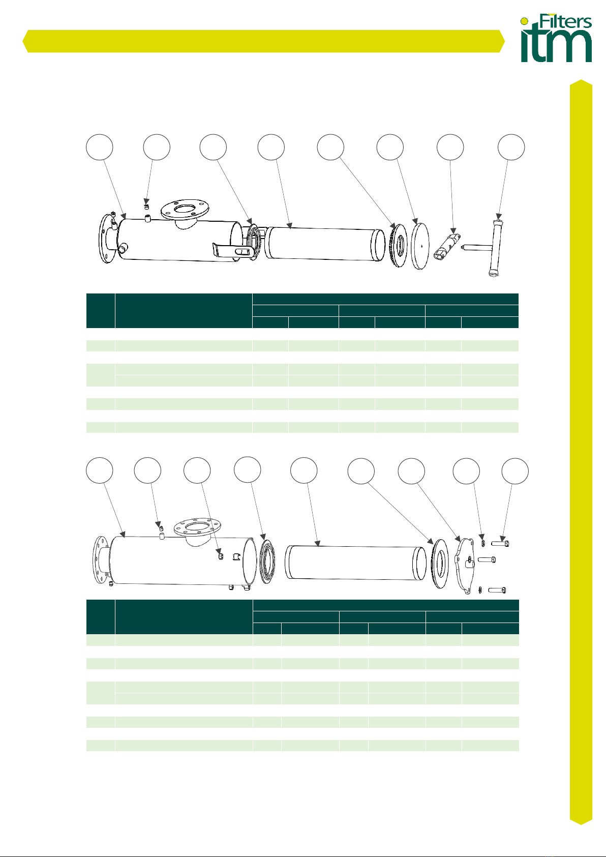
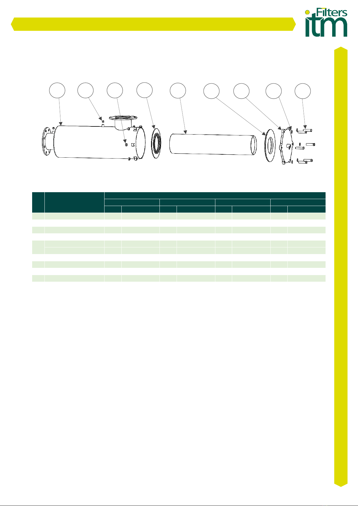
5.4 Exploded view Y Filter –Cyclonic Effect (FY-EC)
Nº
DENOMINATION
FL MODELS
FY-EC-2
FY-EC-3
U.
Code
U.
Code
1
Body
1
FY-EC-2-02
1
FY-EC-3-02
2
Plug ¼ ‘’
2
-
2
-
3
Lower Gasket
1
FY-2-08
1
FY-2-08
4
Plug
-
FY-EC-2-08-01
-
FY-EC-2-08-01
5
Cyclonic Effect Disc
1
FY-EC-2
FY-EC-2
6
Mesh Cartridge-Drip
1
FY-EC-2-04
1
FY-EC-3-04
Cartridge ø2 -Sprinkler
1
FY-EC-2-03
1
FY-EC-3-03
7
Upper gasket
1
FY-2-09
1
FY-2-09
8
Cap
1
FY-EC-2-05
1
FY-EC-2-05
9
Crossbar
1
FY-2-07
1
FY-2-07
10
Wing Nut
1
FY-2-06
1
FY-2-06
TABLE 14
Nº
DENOMINATION
FL MODELS
FY-EC-4-220
FY-EC-5
FY-EC-6
U.
Code
U.
Code
U.
Code
1
Body
1
FL-4-220-02
1
FL-5-02
1
FL-6-02
2
Plug
2
-
2
-
2
-
3
Hex nut. M16
3
DIN934
3
DIN934
6
DIN934
4
Lower Gasket
1
FY-4-220-08
1
FY-4-220-08
1
FY-6-08
5
Plug
-
FY-EC-2-08-
01
-
FY-EC-2-08-
01
6
Cyclonic Effect Disc
1
FY-EC-2
FY-EC-2
7
Mesh Cartridge-Drip
1
FY-4-220-04
1
FY-5-04
1
FY-6-04
Cartridge ø2 -Sprinkler
1
FY-4-220-03
1
FY-5-03
1
FY-6-03
8
Upper gasket
1
FY-4-220-09
1
FY-4-220-09
1
FY-6-09
9
Flat washer D16
3
DIN125
3
DIN125
6
DIN125
10
Hex screw M16
3
DIN933
3
DIN933
6
DIN933
11
Cap
1
FY-4-220-05
1
FY-4-220-05
1
FY-6-05
TABLE 15
USER MANUAL FY /FL /FL-PP /FY-EC
11
1
2
3
4
5
7
8
9
6
10
1
2
3
4
5
7
8
9
6
10
11

www.itmfilters.com
Product warranty
1. All ITM FILTERS products are guaranteed for 1 year from the date of invoice.
2. The replacement of defective parts is covered by the warranty, being necessary to
indicate the serial number and allow the verification by our staff.
3. Take into account the user manual for the installation of the product and check the
operating parameters in the technical tables.
4. To obtain a correct filtration, the size of the filter element must be smaller than that of
the substances suspended in the water to be filtered.
5. This warranty will not apply in the event of damage or defects produced in the product
as a result of or related to:
i. Tearing, elimination or manipulation of the identifying label of the product.
ii. Improper or unauthorized use of the product by the buyer.
iii. An improper assembly or installation that does not correspond to that established
by ITM FILTERS.
iv. The pertinent periodic cleanings.
v. The use of water that does not meet the established quality or is outside the
specifications indicated in the technical tables.
vi. A use of flow discordant with the water quality according to the parameters defined
in the technical tables.
vii. Pressures that differ from the established working pressure.
viii. The wear of materials caused by fatigue, abrasion or high temperatures.
ix. Any external alteration, modification or repair of the products, except by ITM
FILTERS and its technical representatives.
x. Damages produced during the transport of the product.
xi. Third party damage, theft or vandalism.
6. At ITM FILTERS we are committed to quality, which is why we have the ISO 9001, ISO
14001, ISO 45001 and EN 1090 certifications. In addition, during the manufacture of our
filters we have established our own quality control in which we ensure that the product
meets all quality requirements optimally. If you notice any defects, please contact your
dealer.
7. For any claim, it is essential to present this document, the serial code of the
corresponding product and the purchase invoice.
USER MANUAL FY /FL /FL-PP /FY-EC
12
This manual suits for next models
3
Table of contents
Other Filters itm Water Filtration System manuals


Popular Water Filtration System manuals by other brands


Eco Pure
Eco Pure ECOP20 Installation and operation manual

Puretec
Puretec MaxiPlus MP Series user guide

Aqua Medic
Aqua Medic Marin 1000 Operation manual

Aquapure
Aquapure 3MFF100 Installation and operating instructions

AQUA FORTE
AQUA FORTE Tank UV-C manual

Abus
Abus Security-Center ProfiLine TV8727 installation guide


