Elk Products ELK-PD9 User manual

PO Box 100 • Hildebran, NC 28637 USA • 828-397-4200 Voice • 828-397-4415 Fax
http://www.elkproducts.com • email: info@elkproducts.com
PowerDistributionModule ELK-PD9
APPLICATION
The Power Distribution Module(ELK-PD9) conveniently converts a single A.C. or D.C. input into nine individual
outputstocentrallypowerVideoCameras,PIRs,Photobeams,etc. Eachoutputisprotectedwith250mAauto-
resettingPTCstoprotectanyshortedoutputfromdisablingtheotheroutputs. ThemodulehasvisualLEDpower
indicators on each output and a Master Power On/Off Switch with LED on the input. The module requires a 6
to 30 Volt A.C. or D.C. power source (not included) which connects either to a terminal block or a 2.1mm D.C.
power jack located on the module. Note: Refer to Fig 1 for suggested power sources.
FEATURES
!Auto-Resetting (PTC) Overload Protection (NO FUSES to REPLACE).
!Master Power On/Off Switch.
!Visual LED Power Indicators on Input and each Output.
!Convenient Test Points for measuring Total Current Draw.
!Lifetime Limited Warranty.
SPECIFICATIONS
!Max Current Draw from each output: 250mA.
!Max Combined Current Draw: Not to exceed Input Power Source or 2.3A.
!Input/Output Voltage: 6 to 30 Volts A.C. or D.C.
!Input Connection: Screw Terminals or 2.1mm Plug-In DC Jack.
!Output Connection: Screw terminals(POS and NEG) for each output.
!Paintable Plastic Enclosure Size: 6.5" x 4.3" x 2" .
Features and Specifications subject to change without notice.
Low
Cost!
LIFETIMELIMITEDWARRANTY
ElkProducts,Inc.(“Manufacturer”)warrantstotheoriginalpurchaser(the“Customer”)thattheproductsitmanufactures(“Product”)shallbefreefromdefectsinmaterialandworkmanshipattimeofshipment.
Manufacturer’sobligationsunderthisLimitedWarrantyshallbelimitedtorepairingorreplacing,atitsoption,freeofcharge,anyproductreturnedtoManufacturerfreightprepaid.Manufacturershallhavenoobligation
underthisLimitedWarrantyorotherwiseif(1)theProducthasbeendamagedbynegligence,accident,mishandling,lightningorflood,orotherActsofGod,(2)theProducthasnotbeenoperatedinaccordancewith
itsoperatinginstructions,(3)theProducthasbeenalteredorrepairedbyanyoneoutsideManufacturer’sauthorizedfacilities(4)adaptationsoraccessorieshavebeenmadeorattachedtotheProductwhich,in
Manufacturer’ssoledetermination,haveadverselyaffecteditsperformance,safetyorreliability.Productssuchasbatteriesandfusedtransformershavetheirownwarranties,andarenotincludedinthisLimited
Warranty.
IfaProductshouldmalfunctionorfail,contactManufactureroroneofitsauthorizeddistributorsforaReturnAuthorization(RA)number.ReturnedProductsmustincludeacompletedescriptionoftheproblem,along
withtheRAnumberclearlymarkedonoutsideofthepackage.ManufacturerwillnotberesponsibleforanyunnecessaryitemsincludedwithanyreturnedProduct.
THISWARRANTYISTHEEXCLUSIVEWARRANTYFORANYPRODUCT.MANUFACTURERSPECIFICALLYDISCLAIMSANYANDALLOTHERWARRANTIESOFANYKIND,EXPRESSORIMPLIED,
INCLUDINGANYWARRANTIESOFFITNESSFORAPARTICULARPURPOSEOROFMERCHANTABILITY.MANUFACTURERSHALLNOTBELIABLEINTORT,INCLUDINGNEGLIGENCEORSTRICT
LIABILITY,ANDSHALLHAVENOLIABILITYATALLFORINJURYTOPERSONSORPROPERTY.MANUFACTURER’SLIABILITYFORFAILURETOFULFILLITSOBLIGATIONUNDERTHISLIMITED
WARRANTY OR ANY OTHER LIABILITY IN CONNECTION WITH A PRODUCT SHALL BE LIMITED TO THE AMOUNT OF THE PURCHASE PRICE RECEIVED BY MANUFACTURER FOR THE
PRODUCT. THE REMEDIES STATED IN THIS LIMITED WARRANTY ARE THE CUSTOMER’S EXCLUSIVE REMEDIES AGAINST MANUFACTURER REGARDING ANY PRODUCT. UNDER NO
CIRCUMSTANCESSHALLMANUFACTURERBELIABLEFORANYINDIRECT,INCIDENTAL,SPECIALORCONSEQUENTIALDAMAGES,INCLUDINGLOSTPROFITSANDREVENUES,INCONVE-
NIENCE OR INTERRUPTIONS IN OPERATIONS, OR ANY OTHER COMMERCIAL OR ECONOMIC LOSSES OF ANY KIND. THESE LIMITATIONS AND DISCLAIMERS ARE NOT MADE BY
MANUFACTURERWHERE PROHIBITEDBY LAW.SOME STATESPROHIBIT LIMITATIONSOF WARRANTIESAND THECUSTOMER MAYHAVE ADDITIONALRIGHTS IN THOSE STATES.
FormoreinformationcontactyourlocalDistributoror: ELKProducts,Inc. - POBox100 - 3266USHwy.70 West - Hildebran,NC, - 28637 - USA - 828-397-4200
05/02
ELK-PD9 INSTALLATION INSTRUCTIONS
1. ToremovethecoverfromthePowerDistributionModule(ELK-PD9),useasmallobjectlikeascrewdrivertopressintothe
slots located on the end of the cover. Insure that the power switch is off.
2. UsingTable1orTable2below,selectanA.C.orD.C.PowerSource thatprovidesenoughcurrenttopowerthe numberof
devicestobeused.ThePowerSourcevoltagemustalsomatchthedevice'svoltagerequirements.
MountthePower DistributionModulenear thePowerSource thatwillbe used topower the devices.
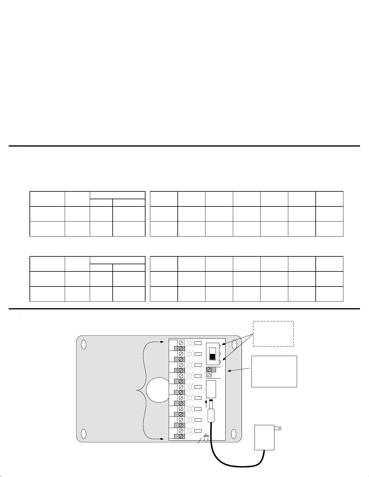
3. Connect thePowerSourcetothePowerDistributionModuleviatheInputPowerTerminalsorthe2.1mmDCjack(J1)located
to the right of the terminals.
4. ConnectatwoconductorcablefromthePowerDistributionModule'sOutputterminalstothedevicestobepowered. Ifdesired,
the total current draw can be measured at the Master Power Switch using an Ammeter while the switch is off. (figure 2)
5. Turn the Master Power Switch on, ensure all leds are on.
6 Replacethe plasticcoveronthePower DistributionModule.
ELK-PD9
POWER DISTRIBUTION
9 OUTPUTS
PTCLED
LED
LED
LED
LED
LED
LED
LED
LED
POS
24VAC or
24VDC or
12VDC
NEG
PTC
PTC
PTC
PTC
PTC
PTC
PTC
PTC
POS NEG POS
POWER 1
NEG POS NEG
POWER 3POWER 2
POS NEG POS
POWER 4
NEG POS
POWER 6POWER 5
POS NEG POS
POWER 7
NEG POS
POWER 9POWER 8
NEG NEG
SW1
J1
CENTER
PIN +
OFF
ON
-
+
CONNECT INPUT
POWER HERE
12 or 24 VOLTS
AC or DC
(30 VOLTS MAX)*
IF DESIRED, USE A CURRENT
METER TO TEST THE TOTAL
CURRENT DRAW AT THESE TEST
POINTS LOCATED ON SW1 LEADS
TURN SW1 OFF BEFORE
MEASURING
* THE INPUT POWER SOURCE
CURRENT MUST BE RATED
FOR THE TOTAL OUTPUT
CURRENT NEEDED
INPUT
POWER ON
LED
OPTIONAL:
12 VOLT DC
PLUG-IN
POWER
SUPPLY
(ELK-T1216)
CONNECT DEVICES TO BE
POWERED TO THESE
TERMINALS
Observe Polarity
if using DC Voltage
* THE INPUT POWER SOURCE
VOLTAGE MUST MATCH THE
DEVICE'S OPERATING
VOLTAGE SPECIFICATIONS
Figure 2: Power Distribution Module(ELK-PD9)
ELK-624
ELK-P1216
ELK-624
12 VDC
12 VDC
24 VDC
1 A
1.5A
.8A
12
18
19
5
7
4
10
15
8
13
20
10
Model # Voltage
Output Amps VA / Watts
Table 2: Quick Power Supply Selection by Number of Devices
Select a column that closely approximates the power consumption of each device. For the
desired voltage, select the row that meets or exceeds the number of desired devices. The
appropriate Power Supply Model # is shown at left. NOTE: If a device consumes more than the
max. rating of a single PD9 output (250 mA), then parallel two or more outputs together to
achieve the desired capacity. Use additional PD-9's for every 9 devices or as required.
@200mA
(2.4W) @100mA
(1.2W) @75mA
(.9W)
Max. Available Power
6
10
5
@150mA
(1.8W)
8
12
6
@125mA
(1.5W)
5
8
4
@175mA
(2.1W)
@200mA
(4.8W) @100mA
(2.4W) @75mA
(1.8W)
@150mA
(3.6W) @125mA
(3W)
@175mA
(4.2W)
4
6
3
@225mA
(2.7W)
@225mA
(5.4W)
Table 1: Sizing the Power Supply
Calculate the total combined power consumption of all
devices. Select a Power Supply which has a Max.
Available Power capacity that meets or exceeds the
calculated total.
Model # Voltage
Output Current VA / Watts
Max. Available Power
ELK-T2440
Transformer 24 VAC 1.7A 40 817 2110 1297
Table of contents
Other Elk Products Control Unit manuals


Popular Control Unit manuals by other brands

Festo
Festo Compact Performance CP-FB6-E Brief description

Elo TouchSystems
Elo TouchSystems DMS-SA19P-EXTME Quick installation guide

JS Automation
JS Automation MPC3034A user manual

JAUDT
JAUDT SW GII 6406 Series Translation of the original operating instructions

Spektrum
Spektrum Air Module System manual

BOC Edwards
BOC Edwards Q Series instruction manual

KHADAS
KHADAS BT Magic quick start

Etherma
Etherma eNEXHO-IL Assembly and operating instructions

PMFoundations
PMFoundations Attenuverter Assembly guide

GEA
GEA VARIVENT Operating instruction

Walther Systemtechnik
Walther Systemtechnik VMS-05 Assembly instructions

Altronix
Altronix LINQ8PD Installation and programming manual


