Elka TERRA 180 User manual
Installation and operating instructions
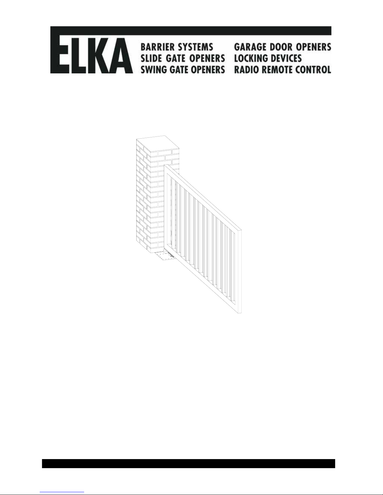
Swing Gate Opener
TERRA 180/182 – TERRA 250/252 –
TERRA 320/322

© 14.11.2005 ELKA-Torantriebe GmbH u. Co. Betriebs KG Page 2 TERRA 180/182 - 250/252 – 320/322
Safety relevant rules and regulations _____________________________________________________________3
General notes of safety _________________________________________________________________________4
1. Usage _____________________________________________________________________________________5
2. Technical Data ______________________________________________________________________________5
3. Installation dimensions (example) ______________________________________________________________6
4. Installation__________________________________________________________________________________7
4.1. Tools needed ______________________________________________________________________________8
4.2. Installation at the gate and gate post __________________________________________________________9
4.2.1. Installation atthegatepost____________________________________________________________________9
4.2.2. Emergency release_______________________________________________________________________10
4.2.3. Emergency releasing _____________________________________________________________________10
4.2.4. Engaging of emergency release ____________________________________________________________10
4.2.5. Installation at the gate ____________________________________________________________________11
4.3. Checking of the movement _________________________________________________________________12
4.4. Adjusting of the internal stops with the MO36__________________________________________________13
4.5. Removing of adjustment clip ________________________________________________________________18
4.6. Mounting of cover plate ____________________________________________________________________19
4.7. Re-adjusting of internal stops _______________________________________________________________20
5. Installation example_________________________________________________________________________21
6. Electrical installation ________________________________________________________________________21
7. Connection plan of the controller MO36 ________________________________________________________22
8. Programming MO36 _________________________________________________________________________25
8.1. Learning sequence ________________________________________________________________________25
8.1.1. Sequence P1: Learning of the running distance_______________________________________________26
8.1.2. Sequence P2: Adjusting of force and speed__________________________________________________27
8.1.3. Sequence P3: Time lag of the pedestrian wing (closing)________________________________________27
8.1.4. Sequence P4: Time lag of the main wing (opening) ____________________________________________27
8.1.5. Sequence P5: Learning and deleting of code for radio remote control for BT, BTG and MULTI________28
8.1.6. Sequence P6: Automatic closure for complete opening ________________________________________28
8.1.7. Sequence P7: Automatic closure for pedestrian wing__________________________________________29
8.1.8. Sequence P8: Warning prior to opening and closing___________________________________________30
8.1.9. Sequence P9: Photo-cell function __________________________________________________________30
8.1.10. Sequence PA: Photo-cell testing __________________________________________________________31
8.1.11. Sequence PB: Lockage function for the photo-cells __________________________________________33
8.1.12. Sequence PC: Pressure relief of electromechanical bolt_______________________________________34
8.1.13. Sequence PD: Wind blast suppression _____________________________________________________34
8.1.14. Sequence PE: Multi-functional relay _______________________________________________________34
8.1.15. Sequence PF: Return to original settings ___________________________________________________35
9. Safety contact profiles for gate open (SLA) and close (SLZ)________________________________________35
10. Additional functions and additional modules ___________________________________________________36
11. Power failure______________________________________________________________________________37
12. Fault diagnosis ____________________________________________________________________________37
13. Technical data MO36 _______________________________________________________________________38

© 14.11.2005 ELKA-Torantriebe GmbH u. Co. Betriebs KG Page 3 TERRA 180/182 - 250/252 – 320/322
Safety relevant rules and regulations
The swing gate controller MO36 has been developed and manufactured according to EN12453 Industrial
commercial and garage doors and gates – Safety in use of power operated doors - Requirements. All notes
in this instruction have to be obeyed by the user. All work and repairs on electrical appliances must be
carried out by qualified persons only. They have to be knowledgeable about the relevant regulations. They
have to be able to recognise possible safety hazards and take necessary safety actions. The operational
safety of the controller MO36 is only guaranteed during usage as intended.
During installation, initial operation phase, maintenance and testing of the controller the individually relevant
regulations for safety and accident prevention have to be obeyed.
These are the following directives and standards: (list is not necessarily complete):
- EN12445: Industrial commercial and garage doors and gates – Safety in use of power operated
doors – Test methods
- EN12453: Industrial commercial and garage doors and gates – Safety in use of power operated
doors - Requirements
- EN60335-1: Household and similar electrical appliances – Safety –Part 1: General requirements
Power supply: 230Vac, 50Hz, single phase.
Connection: By fixed wiring and main switch (on site) or flexible wiring with cable stress relief device
according European standards.
Symbols:
WARNING! Danger of harm to people and objects
INFORMATION! Important information for installation and operation
REMARK! Remarks for the installation

© 14.11.2005 ELKA-Torantriebe GmbH u. Co. Betriebs KG Page 4 TERRA 180/182 - 250/252 – 320/322
General notes of safety
These operating instructions must be available on site at all times. It should be read thoroughly by all
persons who use, or service the appliances. Improper usage or servicing or ignoring the operating
instructions can be a source of danger for persons, or result in material damage. If the meaning of any part
of these instructions isn’t clear, then please contact ELKA Torantriebe GmbH u. Co. Betriebs KG before you
use the appliance.
This applies to all setup procedures, fault finding, disposal of material, care and servicing of the appliance.
The accident prevention regulations and applicable technical regulations (e.g. safety or electrical) and
environment protection regulations of the country in which the appliance is used also apply.
All repairs on the appliances must be carried out by qualified persons. ELKA Torantriebe GmbH u. Co.
Betriebs KG accepts no liability for damage which is caused by using the appliance for purposes other than
those for which it is built.
ELKA Torantriebe GmbH u. Co. Betriebs KG cannot recognise every possible source of danger in advance.
If the appliance is used other than in the recommended manner, the user must ascertain that no danger for
himself or others will result from this use. He should also ascertain that the planned use will have no
detrimental effect on the appliance itself. The appliance should only be used when all safety equipment is
available and in working order. All faults which could be a source of danger to the user or to third persons
must be eliminated immediately. All warning and safety notices on the appliances must be kept legible.
All electrical periphery equipment which is connected to the appliance must have a CE Mark, which ensures
that it conforms to the relevant EEC regulations. Neither mechanical nor electrical alterations to the
appliance, without explicit agreement of the manufacturer, are allowed. All alterations or extensions to the
appliance must be carried out with parts which ELKA Torantriebe GmbH u. Co. Betriebs KG have defined as
suitable for such alterations, and be carried out by qualified personnel.
Any contravention of these conditions revokes the manufacturer’s guarantee and also the CE Mark and the
user is alone responsible for the consequences.
Our service department is available to answer all queries about these conditions and, of course, about our
appliances.
We reserve the right to make technical improvements without prior notice.
The operation of the system within CEN countries must also be conformant with the European safety-relevant
directives and standards.

© 14.11.2005 ELKA-Torantriebe GmbH u. Co. Betriebs KG Page 5 TERRA 180/182 - 250/252 – 320/322
1. Usage
The TERRA is suitable for one or two-winged gates moving horizontally and having low
wind resistance. For max. width and weight of gate wing see table below.
When usage is different from the above samples, please contact your
supplier.
2. Technical Data
TERRA 180/182
one winged gate /
two winged gate
TERRA 250/252
one winged gate /
two winged gate
TERRA 320/322
one winged gate /
two winged gate
Maximum width of wing * 1.800mm / wing 2.500mm / wing 3.200mm / wing
Maximum weight of wing * 500kg 500kg 500kg
Electromagnetic bolt No No
Yes, required for
wings from 2.500mm
Emergency release on current failure Yes Yes Yes
Opening angle max. 180° 180° 180°
Running time (opening angle 90°) **
(each wing) approx. 12s approx. 12s approx. 16s
Limit stoppers at opened and closed
positions *** Position CLOSE recommended (required for wings from2.500mm)
Position OPEN not required (required for wings from2.500mm)
Power supply 230V, 50Hz 230V, 50Hz 230V, 50Hz
Operating voltage 24 V = 24 V = 24 V =
Duty cycle 50% 50% 50%
Blocking when open / closed Yes Yes Yes
Soft-Start and Soft-Stop Yes, with ramp
function
Yes, with ramp
function
Yes, with ramp
function
Pedestrian opening Yes Yes Yes
Controller, separately (WxHxL) MO36
(
175x260x100mm
)
MO36
(
175x260x100mm
)
MO36
(
175x260x100mm
)
Traffic light Module (optional) Module (optional) Module (optional)
Safety contact profile Separately for OPEN
and CLOSE
Separately for OPEN
and CLOSE
Separately for OPEN
and CLOSE
Weight approx. 47kg / 92kg approx. 48kg / 93kg approx. 49kg / 94kg
Degree of protection IP 44 IP 44 IP 44
Temperature range -20°C up to +70°C -20°C up to +70°C -20°C up to +70°C
Maintenance The maintenance intervals must be decided individually as they are
dependent on the frequency of use. We recommend maintenance at least
once every 12 months.
* gates with low wind resistance Table 1
** depending on the installation dimensions
*** end stops at the main wing are not necessarily required for a gate width up to
2,500mm, but are recommended for position CLOSED.
This manual suits for next models
5
Table of contents
Other Elka Gate Opener manuals


Popular Gate Opener manuals by other brands

Nortek Security & Control
Nortek Security & Control Mighty Mule HD272 installation manual

tousek
tousek TURN 10 Installation and operating instructions

SOMFY
SOMFY AXOVIA 220B RTS installation instructions

Nice HySecurity
Nice HySecurity CBOX1050 Installation and programming manual

CAME
CAME FROG-PM4 installation manual

Aprimatic
Aprimatic ONDA 500 installation instructions


