manuals.online logo
Brands
  1. Home
  2. •
  3. Brands
  4. •
  5. Nice
  6. •
  7. Gate Opener
  8. •
  9. Nice Slight Technical specifications

Nice Slight Technical specifications

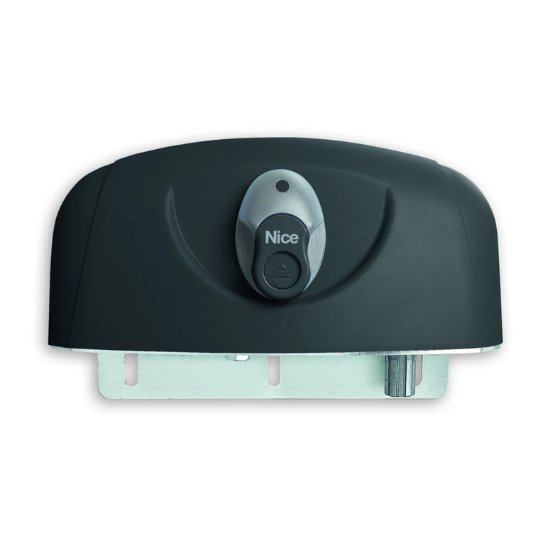
Slight
Instructions and warnings for installation and use
Sliding gate opener
194 0 ÷ 10
191 0 ÷ 50
194 0 ÷ 10
1910 ÷ 50
20÷30
198 191
408
85
1
3 4 5
b
d c cg
i
b
f
h lea
EC FD C F AB
2
6 7
10
8 9
1
2
11
1:2
TX
24V 4W
S.C.A
MOFB
CLOSE
MOSE
LUCYB
OPEN
RX
NC NO CC NO NC
FLASH S.C.A
BLUEBUS
STOP P.P. OPEN CLOSE
14
13
12
15 16
19
18
TX
12
24V 4W
S.C.A
24V 4W
S.C.A
MOFB
CLOSE
MOSE
LUCYB
MASTER SLAVE
OPEN STOP
RX
NC NO CC NO NC
FLASHS.C.A
BLUEBUS
STOP P.P. OPEN CLOSE FLASHS.C.A
BLUEBUS
STOP P.P. OPEN CLOSE
LUCYB
BLUEBUS
12
BLUEBUS
17
20
21
EN
English – 1
ENGLISH
1.1 - Safety warnings
-
 Incorrect installation could lead to serious injury.
Before starting, please read all sections of the manual carefully. If in any

-

Particular warnings concerning the suitable use of this product in relation to the
98/37CE “Machine Directive” (2006/42/CE):
-
fore manufactured to be integrated to a machine or assembled with other
machines in order to create “a machine”, under the directive 2006/42/CE,
only in combination with other components and in the manner described in

use of this product is not admitted until the manufacturer of the machine on

the directive 2006/95/CE.
Particular warnings concerning the suitable use of this product in relation to the
73/23/EEC “Low Voltage” Directive and 2006/95/CE:
-

manual and in combination with the articles present in the Nice S.p.a. prod-

other unforeseen products, the requirements may not be guaranteed; the
use of the product is prohibited in these situations until compliance with the

Particular warnings concerning the suitable use of this product in relation to the
2004/108/CE “Electromagnetic Compatibility” Directive:


instructions manual and in combination with the articles present in the Nice

or with other unforeseen products, the electromagnetic compatibility may not
be guaranteed; the use of the product is prohibited in these situations until

by the installers.


controlling your gate or doorway (see Cahpter 3 and the “Product technical


 If the
power disconnection device cannot be seen from where the automation sys-



-


-

the Nice Support Service.



If the gate being automated has a pedestrian gate, then the system must
include a control device that will inhibit the operation of the motor when the
pedestrian gate is open.

with a contact opening distance that permits complete disconnection under
the conditions dictated by overvoltage category III.


-
nism, far away from its moving parts, at a minimum height of 1.5 m from the
ground and in a location which is not accessible to the public. If it is used in
-
tion mechanism.


are, provide protection for these parts.
-
tem. If you wish to have effective protection, combine the automation mecha-
nism with other security devices.

-



before resetting it.
-

1
Contents

1.1 - Safety warnings ...........................................1
1.2 - Warnings about installation ...................................1
1.3 - Warnings about use ........................................2

 ............................................. 2

 .....................................2
 ...........................................2
3.2.1 - Product durability ...................................... 3
 ............................3
3.4 - Installation of the gear motor . . . . . . . . . . . . . . . . . . . . . . . . . . . . . . . . 4
3.5 - Adjusting the mechanical limit switches . . . . . . . . . . . . . . . . . . . . . . . . .4
 ................... 4

4.1 - Description of the electrical connections .........................4
 ..................... 5

6.1 - Selecting the direction ..................................... 5
6.2 - Connecting to the power supply .............................. 5
6.3 - Recognition of the devices ...................................5
6.4 - Recognition of the length of the leaf ............................5
 .................................. 6
6.6 - Connecting other devices ....................................6

 ................................................. 6
7.2 - Commissioning ...........................................6
 ............................. 6
 ................................. 6

8.1 - Preset functions .......................................... 7
 .........................................7
8.3 - Programming ............................................ 7
 ....................... 8
8.5 - Level 2 programming (adjustable parameters) . . . . . . . . . . . . . . . . . . . 8

9.1 - Adding or removing devices .................................10
9.1.1 - BlueBUS ........................................... 10
  ......................................... 10
9.1.3 - Photocells .......................................... 10
  ................................. 11
9.1.5 - Slight in “Slave” mode . . . . . . . . . . . . . . . . . . . . . . . . . . . . . . . . . 11
9.1.6 - Recognition of other devices . . . . . . . . . . . . . . . . . . . . . . . . . . . . 11
9.1.7 - Radio receiver ....................................... 12
9.1.8 - Connection and installation of the buffer battery .............. 12
9.1.9 -  .................... 12
9.1.10 - Connecting the Solemyo solar energy system . . . . . . . . . . . . . . 12
9.2 - Special functions ........................................ 12
  ............................. 12
  ............................ 12
 . . . . . . . . . . . . . . . . . . . . . . . . . . . . . . . . 12
9.2.4 - Control of the number of manoeuvres performed ............. 13
9.2.5 - Manoeuvre counter reset . . . . . . . . . . . . . . . . . . . . . . . . . . . . . . 13
 .......14
 ......................................... 14
10.2 -Malfunctions archive ..................................... 14
 ................................... 14
10.4 -Signals on the control unit ................................. 15
 ............. 17
 ................................... 18
 ......................... 19
 .............................................. I - VII
EN
2 – English


of wear or damage to electrical cables and mechanical parts. Do not use the
automation mechanism if adjustment or repair is required.



local regulations.

-
-
edge, unless supervised or trained in the use of the product by a person
responsible for their safety.

ensure that they do not play with it.

control devices out of their reach as well.

water; do not use cleaning products or solvents.

premises. 


-

technique permitting connection of multiple devices with only 2 wires.
If powered from the grid, Slight can host a buffer battery (mod. PS124, optional
accessory) which permits the automation mechanism to continue to perform
 In the event of a

 (see paragraph 3.7); or you may use the optional accessory:
the PS124 buffer battery that permits a number of manoeuvres even in the
absence of grid power.

functions and improve security.

2


-

Before proceeding with the installation of 


that they conform to the standards currently in force.





movement is less than half the “nominal torque”. Compare the resulting val-
-
facturers recommend a 50% margin on the force, as unfavourable climatic
conditions may cause an increase in the friction.




to insert the gearmotor and to pass the cables through and connect them.


compliance with local legislation and guarantees a protection of at least IP44
when the lid is closed.

phases of the gate leaves.

guides.



any position.
-
ing; iff necessary, mount the gearmotor raised from the ground.

that it is safe and easy to release it manually.





malfunctions or dangerous situations.





-

device must have contacts with an opening distance large enough to per-
mit complete disconnection under the conditions sanctioned by overvoltage

-
fore be positioned in view of the automation mechanism. If, on the other
hand, it is located in a position which is not visible, there must be a system





needed to determine whether the products are suitable for the intended appli-
cation.

leaves in conformity with the limits indicated in tables 1 and 2.

on the friction as well as other correlated factors, such as ice, that could inter-
fere with the movement of the leaf.

move the leaf throughout its entire run and ensure that this is less than half

50% margin on the force is recommended, as unfavourable climatic conditions

consideration the data indicated in tables 1 and 2 to establish the number of

-
-



-




ambient temperature reducing the manoeuvre further when the temperature is
particularly high.

3

   
  
Up to 4 35
14
4 ÷ 6 23
11


   
  
Up to 200 100%
  
200 - 400 50%
V5 = Very fast

EN
English – 



factors that contribute to product wear, see .

 Add the values of the items in  regarding the system conditions;
 In  from the value obtained above, trace a vertical line until it inter-

estimated life
span of your product.

-
mation of durability is made on the basis of design calculations and the results
of tests performed on prototypes. As it is only an estimation, it does not repre-
sent any form of guarantee on the effective life span of the product.



15% (“Door weight”) and 15% (“Presence of dust, sand or salt”).


-
vre cycles” our product will be able to perform in its life span, about 105,000 cycles.

  
 2 30 m ()
  2 20m
   
 2 30m ()
 2 () 50m
 2 () 30m
 2 () 30m ()
 – 2, and that a safety earthing system is provided
near the automation unit.
 – 2 cable is needed.
 – 22 cables.
 – 
 – special devices which enable connection even when the leaf is moving must be used to connect movable edges to sliding leaves.

0
10 20 30 40 50 60 70 80 90 100
20.000
40.000
60.000
80.000
100.000
120.000
140.000
160.000
180.000
200.000
220.000
240.000
260.000






























La 
:
a 
 Photocells on post
 Photocells
 
e Main movable edge
f 
g 
 
i Slight
 Secondary movable edge (optional)
-
ence to -
ponent envisaged in the system.  – Before installation, prepare the
electric cables required for the system, with reference to  and to “
”.

into account that due to possible deposits of water in the routing ducts, the
connection pipelines might create condensate in the control unit, with conse-
quent damage to the electronic circuits.
EN
 – English





.

-
erwise, in order to mount the gear motor:
 
as a reference the values indicated in ;
 Prepare one or two tubes for the passage of the electricity cables as in 
;
 Assemble the two anchoring devices onto the foundation plate, placing
one nut under and one over the plate; the bolt must be tightened as in 
 so that the threaded part emerges about 25-35 mm above the plate;
 Pour in the concrete and before it starts to set, place the foundation plate

perfectly level, . Wait for the concrete to set fully;
 Remove the 2 nuts above the plate;
 Before proceeding with installation, you should position the door halfway
along its travel and then anchor the gear motor to the foundation plate.

(Paragraph 3.6) and then rest the gear motor on it.
 
tighten the 2 nuts and washers as shown in ;
 
as described in paragraph 3.6.
 
 Release the gear motor as shown in the “Release and manual move-
ment” paragraph in chapter “Instructions and Warnings for users of the
Slight gear motor”.
 Position the leaf in a closing position, leaving it at least 50cm from the


.











throughout the length.




 
 
permit automatic adjustment of the mechanical limit switches. 


();
 

 
-
ual opening and closing of the gate.

failure, malfunctions or during the installation procedures.
 Insert the release wrench ();
 );
 It is now possible to move the leaf into the desired position manually.

4
-
.
 Insert all the connecting cables to the various devices, leaving them 20 to

2 for connections.
 Use a clamp to hold together all the cables that enter the gear motor, and
place the clamp underneath the hole through which the cables enter.
 

 

 

the aerial cable to the other cables.

in Slave mode”.



-
nected. It can also be programmed for other functions; see paragraph “8.4
Level two functions”.

are connected in parallel using two conductors only, through which both the
-
mation about BlueBUS see also paragraph “9.1.1 BlueBUS”.


resistance devices can be connected up using special procedures on the


 = input for devices which control Step-by-Step movement.

 = input for devices which control only the opening movement. It is

 = input for devices which control only the closing movement. It is

 = connection input for the radio receiver aerial (the aerial is incorpo-
rated in LUCY B).
EN
English – 

S.C.A. output on the control unit. In order to program these functions, refer to
paragraph “8.5 Level 2 programming”.
-

ensure the leaf is free to move both during opening and closure.


position of the gear motor with respect to the leaf. If the leaf must move left

alternatively, if the leaf has to move right during opening, the selector must be

 





 
per second.
 

 



carefully.
-
ing for and diagnosing failures.
 
After connecting up the power supply, the control unit must be made to rec-


must be carried out.
    [] and
[Set].
 

around 3s).
 Wait a few seconds until the con-
trol unit has completed the device
recognition procedure.
 When the recognition stage is

remain on, while the L1 and L2
LEDs must go off (LEDs L3 and


6


please see paragraph “9.1.6 Recognition of other devices” in order to per-
form a new recognition.
 


-
urement is required to calculate the deceleration points and the partial opening
point.
    [] and
[Set]
    

s).
     -
gress is an opening manoeuvre.

   
“6.1 Selecting the direction”; then
repeat the process from point 1.
 Wait for the control unit to fully
open the gate by reaching the
opening limit switch; the closing
manoeuvre will start immediately
afterwards.
 Wait for the control unit to fully
close the gate.

-

-
and) in ther gear motor, as follows:
 Press the  or 

 ).
 
limit switch to be adjusted and turn it half a turn (equal to about 3 cm of
movement of the gate) .
 again to open or close the
leaf to register the new position. Repeat as necessary until the leaf reaches
the desired limit switch.


or closing commands ( or ) on the control unit and then send the command

 – If you have already performed manual adjustment and need to repeat
the entire procedure, you can return the limit switches to their initial condition
” sign until the microswitches
are tripped (
 – If, at the start of the installation phase, the leaf is not in the correct
position midway along its travel when the motor is anchored in place and the

the limit switch on one side.
In this case, if the leaf opens until it hits the retainer, without complying with

the direction in which the door moves) toward the “-” sign until the limit switch
is tripped. After this, oversee adjustment of the unit again and use precision
adjustment if necessary.
If necessary, adjust the door length again.
 


Press the 

when it is between 70 and 50 cm from the opening limit switch, and stop,
as a result of the limit switch, at 2-3 cm from the mechanical opening stop.
Press the 

when it is between 70 and 50 cm from the closing limit switch, and stop, as
a result of the limit switch, at 2-3 cm from the mechanical closing stop.






adjustments.


accelerates or decelerates sharply.

5
EN
 – English




switch, it is possible to tap power as shown in


100mA.
- +
24Vcc
-


are functioning correctly.
 – -
-

-


 
Each component of the system, e.g. safety edges, photocells, emergency
-

proceed as follows:
 Ensure that the instructions outlined in this manual and in particular in

 Release the gear motor as indicated in the paragraph “Manually releasing


-



buttons or radio transmitter) test the opening, closing and stopping of the

-
-
forms as it should. In particular, each time a device is activated the “Blue-


 If the dangerous situations caused by the movement of the leaf have
been safeguarded by limiting the impact force, the user must measure the
impact force according to the EN 12445 standard. If the adjustment of the


best results.
 

and the other devices have been terminated successfully. It is not permissible

conditions.
 Prepare and store the technical documentation for the automation for at
-


-
mation system instruction manual and maintenance schedule.
 Post a label on the door providing at least the following data: type of auto-
mation, name and address of manufacturer (person responsible for the

 Post a permanent label or sign near the gate detailing the operations for the
release and manual manoeuvre.
 Prepare the declaration of conformity of the automation system and deliver
it to the owner.
-
tem and deliver it to the owner.
 Prepare the maintenance schedule of the automation system and deliver it
to the owner; it must provide all instructions regarding the maintenance of
the single automation devices.
Before commissioning the automation system, inform the owner in writ-



7



manoeuvre counter and maintenance warning system; see paragraph “9.2.3

 – 


-
sponding maintenance schedules.
1.

2. Disconnect all power supplies (including any buffer batteries).


parts which are below the required standard.

components; if necessary replace them.
 Connect the electric power sources up again, and carry out all the tests




-

-

disposal methods envisaged by the local regulations in your area for this prod-
uct category.
-
stances which, if disposed of into the environment, may cause serious damage
to the environment or physical health.
As indicated by the symbol alongside, disposal of this product
with domestic waste is strictly prohibited. Separate the waste
into categories for disposal, according to the methods estab-
lished by current legislation in your area, or return the product
to the retailer when purchasing a new version.

event of unlawful disposal of this product.
EN
English – 

  
L1  
-
tioning will be “semi-automatic”.
L2  
automatic closure with a pause time of 5s (regardless of the programmed value).

When -

When : the opening manoeuvre stops immediately after the photocells have disen-
gaged. After 5 seconds, the gate will begin to close automatically.

If the “Close after photo” function is inactive the pause time is that which has been programmed or there is no auto-
matic closing if the function is inactive.
  

supply returns, the gate will remain still.
  It is particularly useful in cases when the buffer battery is being used. If this function is active, the control unit will
switch the BLUEBUS output (and consequently the devices) and all the LEDs off one minute after the end of the
-
mand arrives, the control unit will reset to complete functioning. If this function is inactive, there will be no reduction in
the consumption.
  If this function is activated, the gradual acceleration at the beginning of each manoeuvre will be disconnected. It ena-

inactive, the manoeuvre will start with a gradual acceleration.
  


 
 
manoeuvre (see LED L6 on table 7).
 

motors on opposite leaves where one motor functions as Master and the other as Slave; for further information see

 
-

most automations.
 

control unit during tests and programming:
 
gate
 or to move the programming point upwards.
 
Set for if pressed for more than 5 seconds, it enables users to enter
programming
 
 or move the programming point downwards

8 
 control unit, a number of programmable functions are available.
[] [Set] [] and
are used by means of 8 LEDs: .


In this case, each of the LEDs  indicates one function; if it is lit the func-

 the parameters can be adjusted on a scale of values (from 1 to 8).In
this case, each of the LEDs  indicates the set value (there are 8 pos-

L1 will
be on if “Automatic Closing” is active.
EN
 – English

       
  
L2 L1
L2











Step-by-Step 2 (less than 2” causes partial opening)

“Semi-automatic” opening, “Man present “ closing
Manages the sequence of controls
associated to the Step-by-Step input
or to the 1st radio command.



L1 L1
L2






5 seconds
15 seconds
30 seconds
45 seconds
60 seconds
80 seconds
120 seconds
180 seconds
Adjusts the pause time, namely the
time which lapses before automatic
closure. Is effective only if automatic
closure is enabled.


 L1
L2






Very slow
Slow
Medium

Very fast



Adjusts the speed of the motor during
normal travel.


 L1
L2









Active with 2nd radio output
Active with 3rd radio output
Active with 4th radio output
Maintenance indicator

Adjusts the function associated with
S.C.A. output. (whatever the associ-
ated function may be, the output
supplies a voltage of 24V –30 +50%

active).


 L1
L2






Super light gate
“Very light” gate
“Light” gate
“Average” gate
“Averageheavy” gate

“Very heavy” gate
“Super heavy” gate
Adjusts the system which controls
the motor force in order to adapt it

control system also measures the
ambient temperature, automatically
increasing the force in the event of
particularly low temperatures.


 - 
 Press and hold the “Set
 Release the “SetL1
 ” or “  
 Press the “Set
 

SET
SET
SET
L1
or
3 s
10 s
 



-
es made up to that time.
 
 ”
-

-
matically memorising the changes made up to that time.
EN
English – 
 - 
 Press and hold the “Set
 L1
 ” or “ 
changed;
 Press and hold the “SetSet
  
 ” or “” to move the LED representing the parameter value;
 Release the “Set
 
 – Points 3 to 7 can be repeated during the same programming phase in order to set other parameters
SET
SET
SET
SET
L1
or
or
3 s
10 s

 the sequence to follow in order to change the factory settings of the functions for activating “” (L1) and “”

 Press and hold the “Set
 L1
 Press the SetL1 (Automatic closing).
LED L1
 Press the ;
 Press the Set (Always close).
LED 
 
L1 and
 LEDs must remain on.
SET
L1
L3
SET 3 s
L1
SET
L3
SET
10 s
 L1
L2






0.5 mt
1 mt
1.5 mt
2 mt
2.5 mt
3 mt
3.4 mt
4 mt
Adjusts the measurement of the par-
tial opening. Partial opening can be
controlled with the 2nd radio com-

function is present, this becomes



Note: “ ” represents factory settings
All the parameters can be adjusted as required without any contraindication; only the adjustment of the “motor force” could require special care:




occurred in the last 8 manoeuvres
can be established (see paragraph
“10.2 Malfunctions archive”).
 L1
L2






Automatic (depending on the severity of the manoeuvre)
1000
2000
4000
7000
10000
15000
20000
Adjusts the number of manoeuvres
after which it signals the mainte-
nance request of the automation
-
cation”).
-

warning
 L1
L2






Result of 1st manoeuvre (most recent)
Result of 2nd manoeuvre
Result of 3rd manoeuvre
Result of 4th manoeuvre
Result of 5th manoeuvre
Result of 6th manoeuvre
Result of 7th manoeuvre
Result of 8th manoeuvre
-

EN
 – English
 ” to 60 seconds (input on L1
and level on L5) and reducing the “
 Press and hold the “Set
 L1
 Press and hold the “SetSet
 
 Press the 
 Release the “Set
 Press the ;
 Press and hold the “SetSet
 
 Press the L2
11. Release the “Set
12. 
L5
L2
10 s
SET
3 s
L5
SET
SET
L1
L5
SET 3 s
SET
L3 3 s
SET

9
 

any time. In particular, various device types can be connected to “BlueBUS”


-


BlueBUS technology allows you to connect compatible devices using only two
wires which carry both the power supply and the communication signals. All
the devices are connected in parallel on the 2 wires of the BlueBUS itself. It is

because a univocal address is assigned to it during the installation. Photocells,
-

through a suitable recognition process, and can detect all the possible abnor-

to BlueBUS is added or removed the control unit must go through the recogni-




, such as safety
edges can be connected to this input.





suitable arrangements are made.
 
 
  constant resistance output can be con-
nected in parallel; if needed, multiple devices must be connected “in cas-
terminal resistance.
 
 resistance in series


-



By means of addressing using special jumpers, the “BlueBUS” system enables



couples of photocells with the same address.

 
 
 
activated when gate closes
 

closes
 
Internal photocell h = 50 activated when gate
closes
 
Internal photocell h = 100 activated when gate
closes
 

 
Internal photocell activated when gate opens
 
Single photocell for the entire automation system


with the provisions contained in the photocell instruction manual.
EN
English – 11
-

Each time a photocell is added or removed the control unit must go through



C in accordance with the EN1245 standard) and a presence detector which
-


means of the photocell beam, integrating the two systems in a single device.
-
tery thereby eliminating unsightly connection systems; the consumption of the
battery is reduced by special circuits guaranteeing a duration of up to 15 years
(see the estimation details in the product instructions).

level of security of the “main edge”, required by the EN12453 standard for all
“types of use” and “types of activation”, can be attained.

is safe with single faults (class 3 per EN 954-1). It is equipped with a special
anti-collision circuit to prevent interference with other detectors, even not syn-

of transit of heavy vehicles where a second photocell is normally positioned at
1 m from the ground.
-
nection and addressing methods.


this type of function is used when 2 opposite gates need to be automated with



when leaving the factory).


-
BUS.

-

 in the Master e Slave modes, you must follow these opera-
tions:

is to function as Slave or Master; when choosing, one must consider the con-
venience of the connections and the fact that the Step-by-Step command of
the Slave only allows the Slave leaf to be opened fully.


paragraph “6.1 Selecting the direction”).

5).
 Slave (see paragraph “9.1.6
Recognition of the devices”).
 Master (see paragraph “9.1.6
Recognition of the devices”).
 Master (see para-
graph “6.4 Recognition of the length of the leaf”).

16) including
the radio receiver




 
Stand-by Motor speed
 
 
Error list


An open gate light (S.C.A.)
A sensitive edge (Stop)
A command device (Step by Step) that controls the complete opening of
the Slave leaf only




old ones removed, the recognition process can be gone through again by proceed-

 - 
 Press and hold “” and “Set
 L1” and “L2
 Wait a few seconds until the control unit has completed the device recognition procedure.
   

 -

L1
SET
SET L2
L1 L2
EN
12 – English



a distance.


is a description of the association between the radio receiver output and the

 - 
 
 
 
 

  


 .


permitting complete, rapid management of installation, maintenance and diag-

as shown in  and connect up the connector in the housing provided.

particular precautions, up to 60 with the warnings stated) and may be left con-
nected up to the unit during regular operation of the automation mechanism.
In this case, it may be used to send commands directly to the unit using the






  


Refer to the instruction manual provided with the Solemyo system for more
information.
.



to control an opening manoeuvre when the “Step-by-Step” command lasts






In the event that one of the safety devices is not functioning properly or is out of
use, it is still possible to command and move the gate in “Man present” mode.
Please refer to the Paragraph “Control with safety devices out of order” in the

further information.

-

from 8 levels, by means of the “Maintenance warning” adjustable parameter
(see table 7).

the manoeuvre, this being the force and duration of the manoeuvre, while the
other adjustments are established based on the number of manoeuvres.

or by the light connected to the S.C.A. output when programmed as a “Main-
tenance light” (see table 9).

in table 13, based on the number of manoeuvres performed in respect to the
limits that have been programmed.

  
 Normal (0.5s on, 0.5s off) 


-
ries on normally

 
then carries on normally


Other Nice Gate Opener manuals

Nice MC824L User manual

Nice

Nice MC824L User manual

Nice TTN3724RHS User manual

Nice

Nice TTN3724RHS User manual

Nice E SMART SI 620 DC User manual

Nice

Nice E SMART SI 620 DC User manual

Nice GDS 450LI Manual

Nice

Nice GDS 450LI Manual

Nice Toona TO4006 User manual

Nice

Nice Toona TO4006 User manual

Nice Moby Series Product manual

Nice

Nice Moby Series Product manual

Nice wingo 4024 User manual

Nice

Nice wingo 4024 User manual

Nice 7251 Installation manual

Nice

Nice 7251 Installation manual

Nice TTN3724HS Technical specifications

Nice

Nice TTN3724HS Technical specifications

Nice ROX600 User manual

Nice

Nice ROX600 User manual

Nice Toona TO4005 Technical specifications

Nice

Nice Toona TO4005 Technical specifications

Nice ROBO Product manual

Nice

Nice ROBO Product manual

Nice RUN1800 User manual

Nice

Nice RUN1800 User manual

Nice 4024 Kit Technical specifications

Nice

Nice 4024 Kit Technical specifications

Nice HYPPO HY 7005 Installer manual

Nice

Nice HYPPO HY 7005 Installer manual

Nice LFAB4024 Technical specifications

Nice

Nice LFAB4024 Technical specifications

Nice HySecurity CBOX936 Assembly instructions

Nice

Nice HySecurity CBOX936 Assembly instructions

Nice Apollo 8300 SL User manual

Nice

Nice Apollo 8300 SL User manual

Nice HYPPO HY 7005 Technical specifications

Nice

Nice HYPPO HY 7005 Technical specifications

Nice MBar Manual

Nice

Nice MBar Manual

Nice MIGHTY MULE EXIT WAND User manual

Nice

Nice MIGHTY MULE EXIT WAND User manual

Nice DS100 Technical specifications

Nice

Nice DS100 Technical specifications

Nice hyke HK7024 Technical specifications

Nice

Nice hyke HK7024 Technical specifications

Nice 5024 Kit Technical specifications

Nice

Nice 5024 Kit Technical specifications

Popular Gate Opener manuals by other brands

Nortek Security & Control Mighty Mule HD272 installation manual

Nortek Security & Control

Nortek Security & Control Mighty Mule HD272 installation manual

SOMFY AXOVIA 220B RTS installation instructions

SOMFY

SOMFY AXOVIA 220B RTS installation instructions

DoorKing 6500 Series Installation & owner's manual

DoorKing

DoorKing 6500 Series Installation & owner's manual

Centsys D3 user guide

Centsys

Centsys D3 user guide

Chamberlain SGO500 instructions

Chamberlain

Chamberlain SGO500 instructions

Vimar Elvox RA96 Installation and operation manual

Vimar

Vimar Elvox RA96 Installation and operation manual

CAME BX708ALS installation manual

CAME

CAME BX708ALS installation manual

GFA 10003805 00012 installation instructions

GFA

GFA 10003805 00012 installation instructions

ROLLING CENTER GCG2000 Technical data

ROLLING CENTER

ROLLING CENTER GCG2000 Technical data

BFT IGEA Installation and user manual

BFT

BFT IGEA Installation and user manual

SOMFY ELIXO 3S user guide

SOMFY

SOMFY ELIXO 3S user guide

Topens Casar MT8012 user manual

Topens

Topens Casar MT8012 user manual

Forematic RIO-R installation manual

Forematic

Forematic RIO-R installation manual

Chamberlain LA350 installation manual

Chamberlain

Chamberlain LA350 installation manual

GFA ELEKTROMAT SE 9.30-25,40 ER installation instructions

GFA

GFA ELEKTROMAT SE 9.30-25,40 ER installation instructions

Gamatech PK300DC user manual

Gamatech

Gamatech PK300DC user manual

GTO SW-2000 installation manual

GTO

GTO SW-2000 installation manual

DITEC VIVAH quick reference

DITEC

DITEC VIVAH quick reference

manuals.online logo
manuals.online logoBrands
  • About & Mission
  • Contact us
  • Privacy Policy
  • Terms and Conditions

Copyright 2025 Manuals.Online. All Rights Reserved.