Elka EST 4004K User manual
©06.03.06ELKA-Torantriebe GmbH & Co. Betriebs KG Seite 1 ED 200, ED 202, ED 350, ED 352
Installation and Operating Instructions
Slide Gate Openers
EST 4004K
Contents Page
1. Usage 2
2. Technical data 2
3. Measurements 2
4. Installation 3
4.1 Emergency release 4
5. Electrical connections 4
6. Connection example 5
7. MO 44-2 Controller 6
7.1. Connections 7
7.2. Operating mode 8
7.3. Programming 11
8. Timer module (optional) 12
9. Fault codes 13
10. Setting personal code 13
11. General notes to safety 14

© 27.04.2005 ELKA-Torantriebe GmbH u. Co. Betriebs KG Page 2 EST 4004K
1. Usage
For horizontal moving sliding gates either on rails or as a cantilever, up to the weights stated in the technical
data. Please take note of the valid safety regulations.
2. Technical Data
EST 4004K
Maximum weight 4000 kg
Recommended maximum length 16 m
Self blocking at open and closed positions yes
Approximate speed 0.18 m/s
Rack Module 6
Duty cycle 75%
Temperature range -20°C to +70°C
Emergency release yes
Possible height adjustment 30 mm
Housing H x W x L 800x372x270 mm
Opener weight 68,0 kg
Power supply 400 Vac / 50 Hz
Power consumption 2.2 kW
Control box MO44-2
Electronic brake no
The MO 44-2 control box has among others the following characteristics:
Safety: Four separate reactions to the photo-cell.
Automatic test of the photo-cells before each gate movement can be enabled.
Integrated evaluator for safety contact strips with 8.2 kΩterminating resistors.
Actions: Partial opening (e.g. for pedestrians) can be programmed for any position.
Automatic closure can be set separately for completely open and for partially open.
A dead man’s button can also be set.
Separate inputs for OPEN, STOP and CLOSE commands.
The OPEN button can also be transmitted to a further control box (e.g. for a barrier).
Optional timer card for automatic switching between day and night operation.
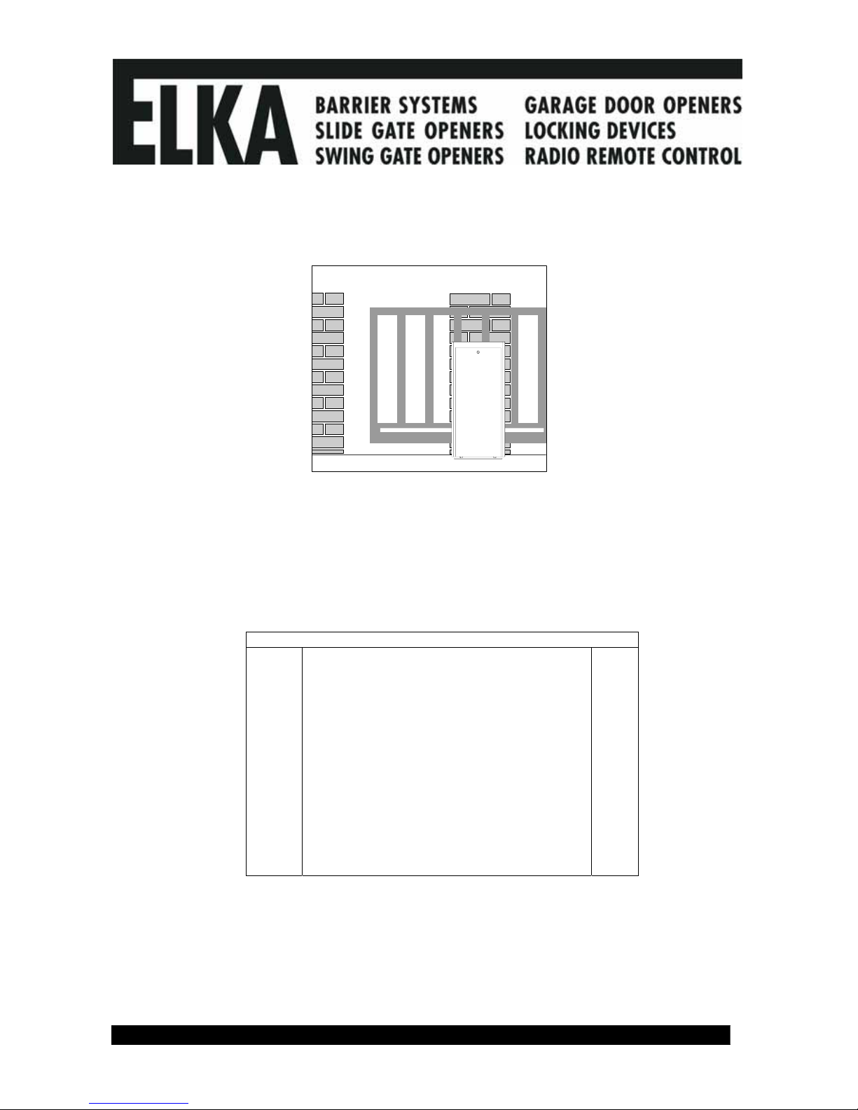
3. Measurements
© 27.04.2005 ELKA-Torantriebe GmbH u. Co. Betriebs KG Page 3 EST 4004K
4. Installation
Ensure that the gate is rigid enough, free moving, and suitable for automation (i.e. enough room to
secure the rack on the gate).
Always disconnect the control box before arc welding is carried out.
7
9
5
11
12
1
2
3
4
5
6
10
13NO
14NO
A1
A2
K1
A1 3L2 5L31L1
A2 4T2 6T32T1
5L313NO3L21L1
6T314NO
K2
4T22T1
13
13
8
a) Using the example in section 6 decide which cables are required and where the control box is to be
mounted (near the opener). The cable should enter the control box from the bottom.
b) Make sure sufficient cable conduit or cable is laid into the foundation which should be free from frost.
The very bottom opener should be at least 30 mm higher than the surrounding terrain and should be as
near as possible to the pivoting point of cantilever gates.
c) Open the access panel of the opener and remove the height adjustment plate. You now have access to
the elongated ground fixing holes.
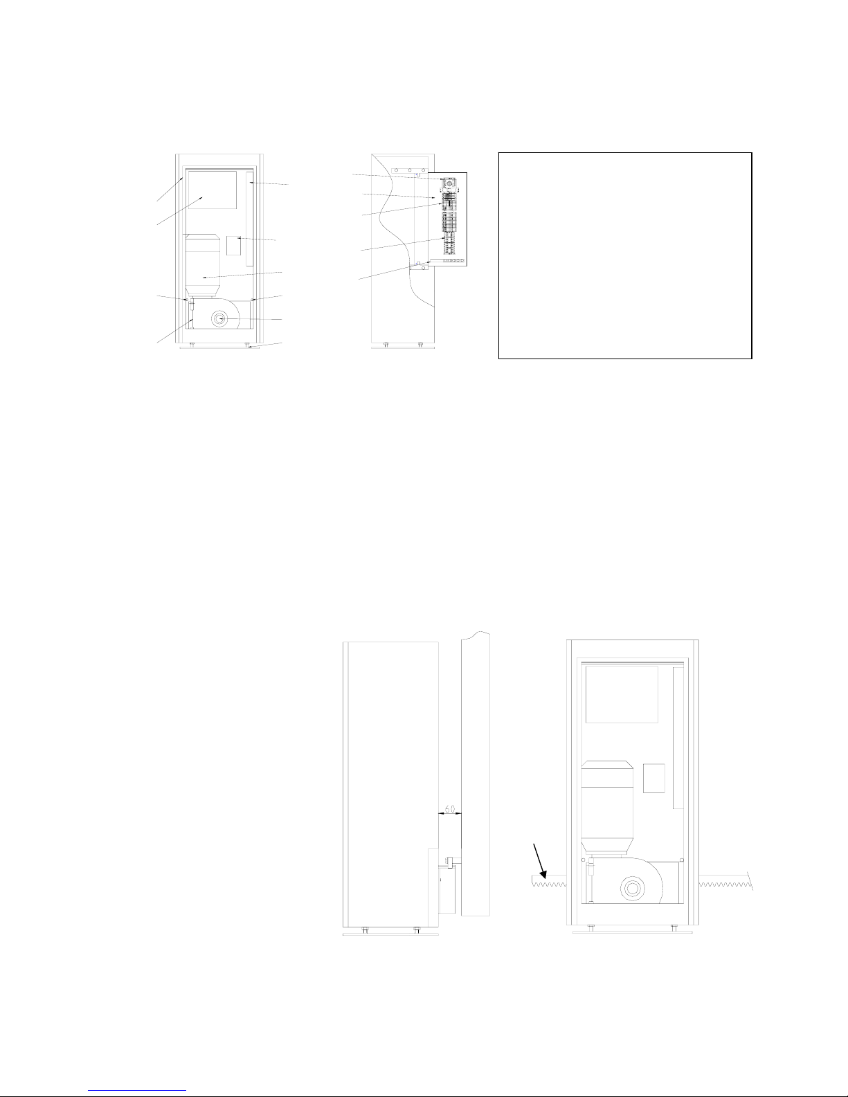
d) Place the opener on the foundation parallel to the gate at a distance of 60 mm. Mark the middle of each
hole on the foundation.
e) Fix the opener, either with plugs and screws (M20), or with heavy duty tie bolts.
e) Decide at what height the rack is to be mounted on the gate. You can use the opener with the height
adjustment plate, or if the rack is to be as low as possible, without the adjustment plate.
g) Using the accompanying tubular “T”-bar disengage the opener (anticlockwise disengages and clockwise
re-engages. See section 4.1.)
h) Mount the rack at the required height on the gate. Don’t use the edges of the gate, always use the pinion
of the opener to determine the
height on the gate.
Lay a length of rack horizontally
on the pinion. Mark the height
of the securing points on the gate
through a hole in the rack. You
may push the gate along while
marking in order to gain a marking
line.
The rack and the pinion should fit
together with minimum play but
enough to ensure that the pinion
does not carry the gate.
1 Aluminium housing
2 MO44-2 Control box
3 Cable clip
4 Terminal block
5 Proximity switch
6 Gear box
7 Power outlet
8 Reversing contactor
9 11 pole socket
10 Motor
11 Emergency release SW22
12 Height adjustment
13 Mounting plate
h)
mark
here
d)

© 27.04.2005 ELKA-Torantriebe GmbH u. Co. Betriebs KG Page 4 EST 4004K
i) Drill holes at the appropriate points to secure the rack and then tap an M8 thread. The rack should
protrude 20cm further than the pinion at both limits of gate movement to allow room for the actuators for
open and closed proximity switches.
j) Screw the distance pieces into the gate, which can also be welded in position.
k) Mount the 1 metre lengths of rack. For better results press a third length (with teeth upwards) against the
joints to produce the required distance between lengths.
l) Push the gate completely open and closed and check that it doesn’t jam. If necessary adjust the height
of the rack.
4.1. Emergency release
Open the access panel and using the accompanying tubular “T” bar (SW22) loosen the hex head screw on
the gearbox.
Turning the bar a couple of turns anti-clockwise disengages the gears.
To re-engage the gears, turn the tee wrench clockwise as far as it will go. (see page 3).
5. Electrical Installation
All cables should have at least the suggested cross-sections.
a) Connect the power supply.
b) The opener closes to the left on delivery. The right limit switch (SEZ) stops the movement.
c) If your gate closes to the right swap the motor leads for „open“ and „close“ and swap the leads to the
terminals SEA and SEZ on the control board.
d) Disengage the opener.
e) Close the gate and push the holding plate with magnet along the rack until the
LED SEZ turns off. Fix the holder at this point on the rack so that the magnet
passes the housing at a distance of about 10 mm.
f) Open the gate and push the holding plate with magnet along the rack until the
LED SEA turns off. Fix the holder at this point on the rack so that the magnet
passes the housing at a distance of about 10 mm.
f) Re-engage the opener and carry out a test run with the gate. Use the push
button BT on the controller card which has serial switching OPEN-STOP-
CLOSE-STOP.
Ensure that the LED SEZ turns off when the gate is closed (not SEA)
otherwise you will have malfunctions (e.g. automatic closing becomes
automatic opening).
g) If necessary readjust the actuators for the proximity switches so that the gate
closes exactly.
h) Connect all periphery equipment.
The time required to open or close the door (running time) must be learned.
Caution:
During the learning mode the gate will move automatically several times.
Ensure nobody will enter the gate area.
Learning the running time: (see section 7.3)
Switch the power regulation on with DIP A1 and DIP A2. Choose a low setting, if required it can always be
increased (see section 7.2.).
Press LT for at least 3 seconds The LED DIAG lights.
Press LT twice. The gate closes from any position, opens completely and closes again. Press the LT button
to confirm, the running time and 10 % reserve and the power required are saved.
The opener is ready for use.
Carry on setting operating mode as described in section 7.2.

© 27.04.2005 ELKA-Torantriebe GmbH u. Co. Betriebs KG Page 5 EST 4004K
6. Connection example

© 27.04.2005 ELKA-Torantriebe GmbH u. Co. Betriebs KG Page 6 EST 4004K
2T1
1L1 1L1
2T114NO6T34T2 A2
13NO
5L33L2
K2
A1
6T34T2 14NO A2
5L33L2
K1
13NO A1
loop
BA1
STOP START
7. MO 44-2 Controller

© 27.04.2005 ELKA-Torantriebe GmbH u. Co. Betriebs KG Page 7 EST 4004K
7.1. Connections
PE Ground Power supply
L1 Phase L1 Power supply. 230 V 50Hz. The LED Vp lights if net voltage is present.
N Neutral Power supply
-------
(N) Neutral
APL-RT Red signal, 230 V max. 60 W. The red light is on when the gate is closed and warning prior
opening is not active.
APL-GN Green signal, 230 V max. 60 W. The green light is on when the gate is open and warning
prior closing is not active.
(N) Neutral
WARN Warning light 230 V max. 60 W. The warning light is on every time the gate moves and also
if a warning prior to moving is active.
The warning light can be used also as red if it’s desired that red turns off when the gate is
closed.
Gate status Warning Red Green
Gate closed Off On Off
Gate open Off Off On
Prior warning and movement On Off Off
Gate stopped in any position in between Off Off Off
Gate stopped at pedestrian position Off Off Off
-------
(N) Neutral for motor (Common for both directions)
AUF Motor open - Direction
ZU Motor close - Direction
EXT-AUF Transmission of the signal BA1 to a second control box (n.o.).
The relay EXT-AUF (max. 24V, 100mA) energises if BA1 is pressed, or the corresponding
remote button is used and falls off after about 1 second. The connection EXT-AUF can be
used to transmit the signal to a open-input to a second control box e.g. for a barrier.
-------
BA1 Button to open the gate (n.o.), the signal is transmitted to terminal EXT-AUF. The LED BA
lights if BA1 or the corresponding remote button is pressed. A permanent open signal is
possible.
BA2 Button to open the gate (n.o.), the signal is valid only for this controller. The LED BA lights
when BA2 is pressed. A permanent open signal is possible.
BZ Button to close the gate (n.o.). The LED BZ lights when pressed. Delayed closing is possible
(see operating mode).
LS Photo-cell (n.c.), or a jumper. The LED LS lights when the photo-cell is interrupted. The
controller can react in three different ways (see section 7.2.). The photo-cell can also be
connected to BS and used as a stop button.
NB Toggle between day and night operating mode, works only when the optional timer card is
being used (see section 8.).
SLZ Safety contact strips (n.c.) for direction “gate closed”, or a resistor (8,2kΩ). The LED SLZ
lights whenever the strips are activated. SLZ causes STOP and reversal for a short way.
SLA Safety contact strips (n.c.) for direction “gate open”, or a resistor (8,2kΩ). The LED SLA
lights whenever the strips are activated. SLA causes STOP and reversal for a short way.
SEA Limit switch „gate open“ (n.c.) . The LED SEA turns off when limit switch is pressed.
SEZ Limit switch „gate closed“ (n.c.). The LED SEZ turns off when limit switch is pressed.
BS STOP button (n.c.) or a jumper. The LED BS turns off when BS is pressed. BS stops gate
movement (electronic brake). The gate can only move again when BS is released and a new
signal is given.
BT Push button for serial switching OPEN-STOP-CLOSE-STOP (n.o.). The LED BT lights when
BT or the corresponding remote button is pressed (see automatic closure, too).

© 27.04.2005 ELKA-Torantriebe GmbH u. Co. Betriebs KG Page 8 EST 4004K
BTG Button for pedestrian opening (n.o.). The LED BTG lights when BTG or remote button is
pressed. If the gate is not in the pedestrian position, BTG will move it there. If the pedestrian
opening is being used without automatic closure, then BTG works with serial switching
OPEN-STOP-CLOSE-STOP.
If automatic closure is on and the gate is at the pedestrian position, the BTG restarts the time
to stay open.
24 Vdc Power supply for periphery equipment.
12 Vdc Power supply for photo-cells and other external equipment.
Maximum total for both outputs
300 mA
LS-TST Power supply for transmitter. The controller switches the 24 Vdc on terminal LS-TST off.
7.2. Operating mode
Motor power (Changes only take effect if the running time is then learned again!)
DIP A1 OFF 100% power.
DIP A2 OFF
DIP A1 OFF 80% power.
DIP A2 ON
DIP A1 ON 70% power.
DIP A2 OFF
DIP A1 ON 60% power.
DIP A2 ON
Photo-cell (Photo-cell connected to BS is stop.)
DIP A3 OFF The opening or closing gate stops when the photo-cell is interrupted and opens when the
DIP A4 OFF photo-cell is free.
DIP A3 OFF The closing gate stops and opens immediately when the photo-cell is interrupted.
DIP A4 ON The opening gate is not effected.
DIP A3 ON The closing gate stops when the photo-cell is interrupted and carries on closing when the
DIP A4 OFF photo-cell is free. The opening gate is not effected.

© 27.04.2005 ELKA-Torantriebe GmbH u. Co. Betriebs KG Page 9 EST 4004K
Automatic closure for partial (pedestrian) opening.
DIP A5 OFF Automatic closure is off.
DIP A5 ON Automatic closure for the pedestrian position is enabled.
If the gate is at the pedestrian position, BTG restarts the time to stay open. The gate opens
completely if BA1 or BA2 is pressed. The gate closes immediately if BT or BZ is pressed.
Automatic closure for completely open.
DIP A6 OFF Automatic closure is off.
DIP A6 ON Automatic closure from the open position is enabled.
If the gate is in open position BA1 or BA2 restart the time to stay open. The gate closes
immediately if BT or BZ are pressed when the gate is open. The gate reopens if BT is
pressed during closing.
Warning prior to opening
DIP B1 OFF No warning.
DIP B1 ON The warning light is switched on 4 seconds before the gate opens.
Warning prior to closing
DIP B2 OFF No warning.
DIP B2 ON The warning light is switched on 4 seconds before the gate closes.
Locking relays / Dead man’s button
DIP B3 OFF The control box works with locking relays.
DIP B3 ON BA1, BA2 and BZ are dead man’s buttons. (The opener stops as soon as the button is
released).
Delayed closing
DIP B4 OFF The opening gate closes immediately when BZ is pressed.
DIP B4 ON If the gate is opening and BZ is pressed, the signal is stored until the gate is open and then
carried out.
Three-phase operation
DIP B5 OFF Drive with single-phase motor (with electronic brake)
DIP B5 ON Three-phase motor (with reversing contactor and mechanical brake)

© 27.04.2005 ELKA-Torantriebe GmbH u. Co. Betriebs KG Page 10 EST 4004K
Photo-cell testing before gate movement
DIP B6 OFF Photo-cell test is not activated.
DIP B6 ON A photo-cell test occurs before each moving.
Attention: The photo-cell test has to be learnt when programming the controller. Before the
moving of the gate, the photo-cells may be tested.
Max. 6 photo-cells can be connected to the controller MO44-2 and be tested. For the testing
of more than one photo-cell the relay connections of the receivers have to be connected in
series. Parallel to the relay connections a resistor of 1kOhm (+/- 5%) each has to be
connected.
The photo-cell test consists of two parts: The transmitter is taken off the power supply and
then the receiver has to report an obstacle (within max. 2.5 seconds).
The transmitter is connected to the power supply again and then the receiver has to report
that no obstacle is present. If during part one the receiver does not report an obstacle, the
photo-cell is faulty. If during part two the obstacle is still being reported (the controller
assumes a real obstacle being present), the gate will not move. No error code is shown.
© 27.04.2005 ELKA-Torantriebe GmbH u. Co. Betriebs KG Page 11 EST 4004K
LT
LT
LT
LT LT
BT
BT BT
BT
BT BT
BTG
BTG BTG
BTGLT
Funk Funk Funk
running time
is stored
all personal
codes are
erased
position for
partial opening
is stored
remote code
for BA1 is
stored
time to stay for
position open
is stored
press 3s
Diag-LED lights
Diag-LED flashes
quickly
Diag-LED lights,
gate opens and
closes, 10 s
reserve are set
Diag flashes
Diag-LED
flashes each
second, set
new reserve
Diag-LED
lights
Diag-LED
lights, BTG is
deadman
button, move
to partial open
position
gate closes
Diag-LED
lights for 3s
Diag-LED
flashes each
second, set
time to stay
open
Diag-LED flashes
quickly
Diag-LED flashes
quickly
Diag-LED
lights for 3s
Diag-LED
lights for 3s
Diag-LED
flashes each
second, set
time to stay
open
remote code
for BT is
stored
time to stay for
partial open is
stored
remote code
for BTG is
stored
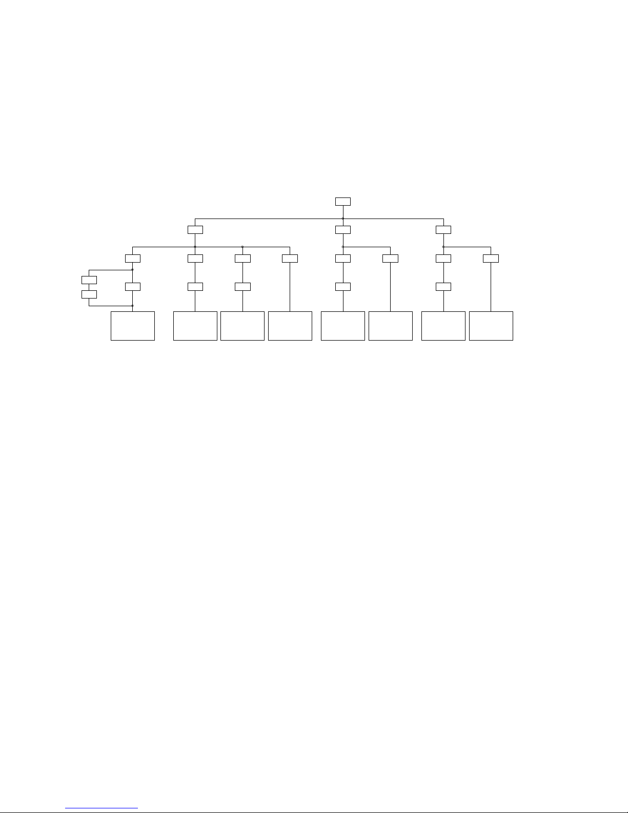
7.3. Programming
The minimum to ensure that the opener works correctly is that the running time must be learned. Other
things like automatic closure, or time which the gate should stay open before closing can also be set during
programming.
The following settings can be altered if required:
Time required to open (running time) (0...150 s, default 30 s)
Reserve for the running time (0...10 s, default 10 s)
Time to stay open before automatic closure (0...300 s, default 20 s)
Time to stay open before automatic closure from partial position (0...300 s, default 20 s)
Position for partial opening for pedestrians (any position, default half way)
Remote control codes for BT, BTG and BA1 (default BT -+-+...)
Learning the time for opening (running time) and reserve
Press LERN until the LED DIAG lights (approx. 3 seconds).
Press LERN twice.
The gate closes from any position, opens completely and closes again. The time required and the power
selected (DIP A1 and DIP A2) are then saved. The LED DIAG starts flashing quickly, the running time is
learned. Press LERN if you want to accept the default value for the running time reserve (10 s). The
controller is ready for use.
If you want to change the running time reserve press BT, the LED DIAG flashes in 1 second intervals, press
BT when the required time has elapsed. The controller is ready for use.
The position for partial opening is automatically set to half way when the running time is learned, this means
that any other value for pedestrian opening must be learned after the running time!
Learning partial opening for pedestrians
Press LERN until the LED DIAG lights (approx. 3 seconds).
Press LERN once. The LED DIAG flashes quickly.
The BTG button moves the gate in dead mans mode. When the gate is at the required position press LERN.
The gate closes automatically and the information is stored. The controller is ready for use.
Learning the time to stay open before automatic closure (completely open)
Press LERN until the LED DIAG lights (approx. 3 seconds).
Press BT twice. The LED DIAG flashes in 1 second intervals.
When the time required has elapsed press BT again.
The time is stored and the controller is ready for use. The time is only effective when automatic closure is on
(DIP A6 ON).
Learning the time to stay open before automatic closure (partial opening for pedestrians)
Press LERN until the LED DIAG lights (approx. 3 seconds).
Press BTG twice. The LED DIAG flashes in 1 second intervals.
When the time required has elapsed press BTG again.
The time is stored and the controller is ready for use. The time is only effective when automatic closure is on
(DIP A5 ON).

© 27.04.2005 ELKA-Torantriebe GmbH u. Co. Betriebs KG Page 12 EST 4004K
Learning the remote control code for BT
Press LERN until the LED DIAG lights (approx. 3 seconds).
Press BT once. The LED DIAG flashes quickly. Press the appropriate button of your transmitter.
The LED DIAG stays on as long as a signal is received. Release the button. The code is stored and the
controller is ready for use.
Learning the remote control code for BTG
Press LERN until the LED DIAG lights (approx. 3 seconds).
Press BTG once. The LED DIAG flashes quickly. Press the appropriate button of your transmitter.
The LED DIAG stays on as long as a signal is received. Release the button. The code is stored and the
controller is ready for use.
Learning the remote control code for BA1
Press LERN until the LED DIAG lights (approx. 3 seconds).
Press LERN once. The LED DIAG flashes quickly. Press the appropriate button of your transmitter.
The LED DIAG stays on as long as a signal is received. Release the button. The code is stored and the
controller is ready for use.
8. Timer card (optional)
The 7-day-timer can switch between day and night operating.
Day: A continuous signal to open is given in order to hold the sliding gate open. All Signals from BA1 are
sent to EXT-AUF for a further control box.
Night: All signals from BA1 operate the sliding gate and are sent to EXT-AUF for a further control box.
Holidays: The switch NB (night operation) can override the timer. If NB is closed, night operation is active
independent of the status of the timer. The timer has control when NB is open.
Forcing day operation at night: A continuous signal to BA2 opens the sliding gate and keeps it open
independent of the timer status.
Times NB Gate status
Off Doesn’t matter Does not affect the gate
Switches on Off The gate opens
On Off The gate is held open
Switches off Off The gate closes
On Switches on The gate closes, night operation is forced
On Switches off The gate opens, day operation is continued
Doesn’t matter On Does not affect the gate

© 27.04.2005 ELKA-Torantriebe GmbH u. Co. Betriebs KG Page 13 EST 4004K
9. Fault code
The following faults are detected by the controller and reported as a code with
the DIAG and remote control LED:
Code Fault
DIAG 2 flashes Both limit switches are activated. Check the switches and wiring.
DIAG 3 flashes Photo-cell testing unsuccessful.
DIAG 4 flashes Safety contact stripes (SLA) testing unsuccessful.
DIAG 5 flashes Safety contact stripes (SLZ) testing unsuccessful.
DIAG 6 flashes Running time error message. Check the switches or repeat the
learning of the running time.
DIAG 7 flashes The power supply limit for the external equipment 12 V has been
reached. The power source load is too high. The controller is
blocked.
DIAG 8 flashes The power supply limit for the external equipment 24 V has been
reached. The power source load is too high. The controller is
blocked.
DIAG 9 flashes The memory has lost the data. Repeat the learning of the running
time.
DIAG 10 flashes The controller is faulty.
DIAG 11 flashes The controller has detected a fault in the redundant detection of
BS (stop contact). The controller is faulty.
DIAG 12 flashes The controller detects that the TRIAC or one of motor relays is
faulty.
10. Setting personal code in the K Type radio remote control
Example A) Receiver using the code switches on the logic board : MO 33, MO 43 or MO 542
or receiver with code switches in conjunction with the boards : MO 32, MO 42, MO 52Z2, MO 60 or MO
62
Follow the example in the diagram below.
Transmitter SK, SKX and SKI in conjunction with K Type receivers using code switches.
The switches 1 to 7 in transmitter and receiver must have the same settings. The switches 8 and 9 of the
receiver allocate a channel appropriate to the button of the transmitter. The switches 8 and 9 in
multi - channel must be set at 0.
The examples on the right in the diagram above show the allocation of a channel with a one - channel
transmitter using the switches 8 and 9 as in the receiver.
Example B) Receivers without code switches : Logic boards MO 34, MO44 or MO 55
These receivers learn the code from the transmitter as described in the paragraph ‘Learning personal code’
in these installation instructions.

© 27.04.2005 ELKA-Torantriebe GmbH u. Co. Betriebs KG Page 14 EST 4004K
Example C) Combination of examples A and B
A garage door opener with MO 55 and a swing gate opener with either MO 32 or MO 33.
1.) Set the code of the transmitter and receiver for the swing gate opener as described above. Switches 1
to 7 have the same settings in both transmitter and receiver. The switches 8 and 9 set at 0.
The swing gate opener now receives signals from the first button of the transmitter.
2.) You can now allocate the second button to the garage door opener by going through the procedure
described in the installation instructions for the garage door opener in the paragraph ‘Learning
personal code’.
11. General Notes to Safety
These operating instructions must be available on site at all times. It should be read thoroughly by all
persons who use, or service the appliances. Improper usage or servicing or ignoring the operating
instructions can be a source of danger for persons, or result in material damage. If the meaning of any part
of these instructions isn’t clear, then please contact ELKA Torantriebe GmbH & Co. Betriebs KG before you
use the appliance.
This applies to all setup procedures, fault finding, disposal of material, care and servicing of the appliance.
The accident prevention regulations and applicable technical regulations (e.g. safety or electrical) and
environment protection regulations of the country in which the appliance is used also apply.
All repairs on the appliances must be carried out by qualified persons. ELKA Torantriebe GmbH & Co.
Betriebs KG accepts no liability for damage which is caused by using the appliance for purposes other than
those for which it is built.
ELKA Torantriebe GmbH & Co. Betriebs KG cannot recognise every possible source of danger in advance. If
the appliance is used other than in the recommended manner, the user must ascertain that no danger for
himself or others will result from this use. He should also ascertain that the planned use will have no
detrimental effect on the appliance itself. The appliance should only be used when all safety equipment is
available and in working order. All faults which could be a source of danger to the user or to third persons
must be eliminated immediately. All Warning and Safety notices on the appliances must be kept readable.
All electrical periphery equipment which is connected to the appliance must have a CE Mark, which ensures
that it conforms to the relevant EEC regulations. Neither mechanical nor electrical alterations to the
appliance, without explicit agreement of the manufacturer, are allowed. All alterations or extensions to the
appliance must be carried out with parts which ELKA Torantriebe GmbH & Co. Betriebs KG have defined as
suitable for such alterations, and be carried out by qualified personnel.
Any contravention of these conditions revokes the manufacturer’s guarantee and also the CE Mark and the
user is alone responsible for the consequences.
Our service department is available to answer all queries about these conditions and, of course, about our
appliances.
We reserve the right to make technical improvements without prior notice.
The operation of the system within CEN countries must also be conformant with the European safety-
relevant directives and standards.
Table of contents
Other Elka Gate Opener manuals


Popular Gate Opener manuals by other brands

Allmatic
Allmatic IND4000V/T manual

Chamberlain
Chamberlain BG 3100-X1 Installation and operation instructions

Mighty Mule
Mighty Mule FM500 installation manual

SEA
SEA COMPACT 200 CP Fitting and Connection Instructions

tau
tau ARM200 Series Use and maintenance manual

tau
tau R18 series Use and maintenance manual


Daspi
Daspi DS 301 manual

Avidsen
Avidsen STYRKA400 quick start guide

Erreka
Erreka MAGIC Installer manual

Mhouse
Mhouse WG20 Installation instructions and warnings

Dea
Dea REV Series Operating instructions and warnings

Wallace Perimeter Security
Wallace Perimeter Security SPEEDGATE Installation and maintenance manual