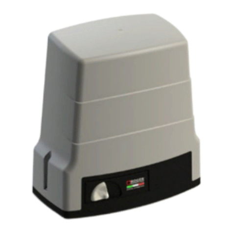
Elka EST 204 User manual

Installation and operating instructions
Slide Gate Openers
EST 204 – EST 404 - EST 804
Contents : Page
1. Usage 2
2. Technical Data 2
3. Measurements 2
4. Installation 3
5. Emergency release and height adjustment 3
6. Mounting the rack 4
7. Electrical setup (Connection examples) 5
8. MO 56/S controller for EST 204 / 404 6
9. Operating modes MO56 (DIP switches) 7
10. Safety functions MO56 8
11. Learn mode MO56 9
12. After power break / emergency mode 11
13. Error codes MO56 11
14. MO 43 controller for EST 804 12
15. Operating modes MO43 (DIP switches) 13
16. Setting personal code for radio remote 15
17. General notes to safety 16

©09.02.2006 ELKA-Torantriebe GmbH u. Co. Betriebs KG page 2 EST 204, EST 404, EST 804
1. Usage
The sliding gate openers EST 204 / 404 and EST 804 are designed for horizontal moving gates either
running on a rail, or cantilever types. Please take note of the valid safety regulations.
2. Technical Data
3. Measurements (in mm)
Measurements of EST 204 / 404
Measurements of EST 804
EST 204 EST 404 EST 804
Power supply 230 V 50 Hz 230 V 50 Hz 230 V 50 Hz
Motor Voltage 24 V= 24 V= 24 V=
Force 800 N 800 N 800 N
Maximum weight /length of gate 200 kg / 5 m 400 kg / 6 m 800 kg / 8 m
Approximate speed of movement 0.26m/s 0.17m/s 0.17m/s
Controller MO 56/S MO 56/S MO 43
Soft-Start and Soft-Stop yes yes yes
Input terminals for button BT BT BT, BTA, BTZ, BTG
Input terminal for stop yes, redundant yes, redundant yes
Photo-cell functions 2 modes – testable 2 modes – testable 3 modes
Evaluation of safety contact strips yes, separate open/close yes, separate open/close integrated
Automatic closure selectable (max. 300 s) selectable (max. 300 s) selectable
Partial opening for pedestrians yes, with radio command yes, with radio command optional, radio and button
Prewarning separate for open and close selectable selectable selectable
Traffic lights yes, red / green yes, red / green ---
Light max. 500W max. 500W ---
Dead man’s button (hold to run button) yes, in emergency mode yes, in emergency mode selectable
Degree of protection IP56 IP56 IP56
Approximate net weight 11 kg 11 kg 13.5 kg
385
111 - 141
72 - 102
204
10x25
92
65
154
30x65
175 238
77
108 216
246
209175
72 - 102
111 - 141
8.4
65
246
216
108
204
30x65
154 92
77 10x25
302

©09.02.2006 ELKA-Torantriebe GmbH u. Co. Betriebs KG page 3 EST 204, EST 404, EST 804
4. Installation
End stoppers must be used at the ‘open’ and ‘closed’ positions.
The stopper for the closed position should also prevent that contact strips are squashed if they are
being used.
a) The foundation must be free from frost, and the opener must stand at least 30 mm higher than the
surrounding terrain and at least 100 mm from the gate opening. Decide what cables are required. Make
sure sufficient cable conduit or cable is laid into the foundation. Using the example in section 7.
b) Loosen the four screws and remove the hood.
c) You now have access to all holes for cables and ground fixation.
d) Place the opener with 65 mm distance from the gate with the back parallel to the gate.
e) Mark the middle of the elongated holes on the foundation.
f) Take the opener from the foundation and drill holes for 8 mm diameter plugs or anchor bolts.
g) Lay the 0.5 mm cardboard between the opener and the foundation and secure the opener with the anchor
bolts.
5. Emergency release and height adjustment.
To disengage the opener open the lock (only as option with the EST 804). Insert the 6 mm hexagonal key
into the hole marked X and turn it anticlockwise 180°. The pinion is now disengaged from the rack and the
controller is switched off. The height of the pinion axis is 87mm on delivery and can be altered +15 mm/ -
15mm if required. Check that the opener can still be disengaged after adjusting the height.
Pinion
6 mm
hexagonal
key
x
Part to switch
controller off
Switch is off when
disengaged
Motorholder, the height
to the shaft middle is
ca. 87 mm on delivery
Adjustment of the motor
holder + or - 15 mm
possible

©09.02.2006 ELKA-Torantriebe GmbH u. Co. Betriebs KG page 4 EST 204, EST 404, EST 804
6. Mounting the rack
a) The rack is delivered in lengths of 1 meter. The two lengths with springs are to be mounted on the left and
right end.
No warranty if the rack is used without these springs!
b) Disengage the opener and close the gate manually and mark during closing the mounting height for the
rail on the gate (149 mm above the base plate of the opener).
c) Drill holes Ø 6,5 mm in the intervals as shown below. Tap M8 threads.
d) Screw the distance pieces into the gate.
e) Fix the first length of rack and ensure that the spring is fitted inside. Don’t tighten the screws until the
assembly is complete.
f) Push five plastic rack segments into the rail, hooked together as shown below. Push the segments into
the rail until they are against the spring. The fifth segment will protrude.
g) Hooked six segments of rack together and insert into the next length of rail so that they protrude at both
ends.
h) Hook the protruding end into the protruding end of the first length. Push this rail against the first rail.
j) Screw this length onto the distance pieces.
k) Connect the butt joint of the two lengths of rail with
the connecting piece.
l) Carry on in this way until only the length of rail with
the second spring remains.
m) The last segment of plastic rack must be cut off so that it fits flush against the spring.
n) Re-engage the opener (turn hexagonal key 180° clockwise).
o) Push the rack lightly onto the pinion and check that the teeth are fully engaged. Make any necessary
corrections. Tighten all screws.
p) Disengage the opener and push the gate until the next joint in the rack and carry on as under (o).
q) Carry on in this way until the rack has been checked in its entire length.
r) Remove the cardboard from under the opener.
s) Tighten the securing screws for the opener.
t) A test run of the gate to check the rack will be done during the setup of the controller.
Check that the rack is correctly mounted and that all screws are tight.
The emergency release must work at every position of the gate.
Connecting piece for sections of rack

©09.02.2006 ELKA-Torantriebe GmbH u. Co. Betriebs KG page 5 EST 204, EST 404, EST 804
7. Electrical Setup
a) Check if the gate closes to the right or to the left.
If the gate closes to the right as seen from the opener, the motor connectors are: M - green M+ red.
If the gate closes to the left as seen from the opener, the motor connectors are: M - red M+ green
b) Connect all external devices
EST 204 / 404 opener control box MO 56/S section: 8.
EST 804 opener control box MO 43 section: 10.
c) Check the setting of DIP switches for the functions you need.
EST 204 / 404 opener control box MO 56/S section: 9.
EST 804 opener control box MO 43 section: 15.
d) Go through to learning (programming) mode
EST 204 / 404 opener control box MO 56/S section: 11.
EST 804 opener control box MO 43 section: 10.
Caution:
During the learning mode the gate may move automatically several times.
Ensure nobody will enter the gate area.
The opener is ready for use.
Connection example EST 204 / 404
Connection example EST 804

©09.02.2006 ELKA-Torantriebe GmbH u. Co. Betriebs KG page 6 EST 204, EST 404, EST 804
8. MO 56/S controller for EST 204 / 404
8.1. Input terminals MO 56/S
Terminal Contact Function
BT n.o. Serial button. The function of BT is depending of the status of the operation mode
automatic closure (DIP 1)
- with automatic closure: BT opens or restarts the “stay open time”.
- without automatic closure: BT offers the sequence open – stop – close - stop.
TS n.c. Stop contact
When TS is active, the gate cannot be operated.
LS n.c. Photocell contact. The function of LS is depending of the status of the operation
mode photocell (DIP 5).
When LS is active, the gate cannot be operated or the gate opens immediately.
Masse Ground for BT, TS and LS.
Sync n.c. Button for manual release. When opener is released, the control box is switched off.
Radio Socket for radio remote receiver EKX1OF.
SLZ
SLA Safety contact strip, separate for open (SLA) and close (SLZ) with 8,2 kOhm resistor.
Two evaluation units with testing are integrated.
IMP Incremental pulses from motor
PE Earth
0V, 14V,
28V From the transformer
Red light/
warning light
3 min light
Green light
Learn-button
Serial button
SL
Diag.
BT
LSVp
OFF
ON
Gnd
SLA
BT
TS
LS
Gnd
SLZ
Motor
IMP
24Vd
c
Hall-Sensor
0V 14V
0V 14V
0V 14V
0V 14V
LS-
Transm.1
LS-
Transm.2-6
LS-
Receiver 1
LS-
Receiver 2-6
Sync
14V 0V 28V
PE M- M+
Transformer
14V0V 28V
N
PE
F1 2A F2 10A
L1

©09.02.2006 ELKA-Torantriebe GmbH u. Co. Betriebs KG page 7 EST 204, EST 404, EST 804
8.2. Output terminals MO 56/S
Terminal Function
14Vac for
LS-transmitter Supply for the photocell transmitter. Performs necessary supply interruption during LS
test.
14Vac for
LS-receiver Supply for the photocell receiver.
0Vac Common for photocell transmitter and receiver.
Motor +
Motor - Motor connector, for motor types: 1x 404.258, 2x 404.258, 1x 404.259, 2x 404.259, 1x
404.458
Light 3min. Light. Potential free contact. Maximum load 230V/500W.
Green traffic light Green is on when gate is completely open.
Potential free contact. Maximum load 230V/120W.
Red traffic light /
Warn light Red is off, when the gate is completely open or when it is completely closed. Red is on
during movements, during warning times and when gate stops in between.
Potential free contact. Maximum load 230V/120W.
8.3. Indication lights on the MO 56/S
LED name Colour Function
BT green On, when contact BT is closed.
LS green On, when at least one photocell contact (LS) is open.
SL red On, when SLA or SLZ safety edge is pressed.
Vp yellow On, when power supply is present.
Diag/Funk yellow Diagnosis display and display for radio receiver.
9. Operation modes MO 56/S (DIP switches)
Alter only when power supply is switched off.
After altering the DIP switch mode confirm with the button LERN.
9.1. Automatic closure (S1)
When automatic closure is active, the stored pause time starts to elapse, every time the gate has reached
the position completely open. When the stored time has elapsed, the gate will close automatically.
If the gate is completely open and a stop command is given (TS), the function automatic closure is blocked.
Automatic closure will be activated again and the pause time will start new, when button BT or radio
transmitter is used.
When the gate is completely open and LS is active, the gate will stay open even after the pause time has
elapsed. LS prevent the gate from closing, but the pause time is not extended. If LS is not active any more
and the pause time has elapsed already, the gate will close immediately.
S1 off: Automatic closure is off
S1 on: If gate is completely open, it will close automatically after the stored pause time has
elapsed. (choose from 0 up to 300 s, default 30 s)
9.2. Warning prior to opening (S2)
When warning prior opening is activated, the open command will start the warning light first. The gate will
open after the warning time has elapsed.
S2 off: no warning prior to opening
S2 on: 4 s warning time prior to opening is active
9.3. Warning prior to closing (S3)
When warning prior to closing is activated, the close command will start the warning light first. The gate will
close after the stored warning time has elapsed.
S3 off: no warning prior to closing
S3 on: warning time prior to closing is active (choose from 0 up to 300 s, default 5 s)
9.4. Photocell test (S4)
Photocell may be tested prior to every movement of the gate where the observation through photocell is
active.
S4 off: Photocell test is off
S4 on: Prior to every movement the photocells are tested. The gate can only move when
photocells are without malfunction.
Caution: The number of photocells has to be stored before using the test.(cha. 9.6)

©09.02.2006 ELKA-Torantriebe GmbH u. Co. Betriebs KG page 8 EST 204, EST 404, EST 804
9.5. Photocell function (S5)
You may choose between two functions.
S5 off: LS is used during opening and during closing.
When obstacle is detected, the gate stops. After obstacle is gone, the gate opens.
S5 on: LS is used during closing only.
When obstacle is detected, the gate stops and opens immediately.
9.6. Timing or impulse logic (S6)
S6 on: Controller works as impulse logic (max. 60000 pulses per opening). Pulse cable
from motor to controller is needed.
10. Safety functions MO 56/S
10.1. Stop contact
When contact TS is open (LED is on) no gate movement is possible. Using TS during a gate movement
stops the gate immediately. The automatic closure is blocked when TS is being used.
10.2. Force detection
During the learn mode the controller analyses and stores the required forces to open and close the gate. In
the operation mode the actual force is compared with the stored force value. If the actual force is higher than
the stored value plus a certain extra, the controller commands a stop and a short distance reversal (for 1s) to
free the obstacle.
10.3. Running time control
If the gate doesn’t reach the end position closed at the (impulse) calculated position, the motor will continue
to run for maximal 30s. The pulse counter is set to zero at the new position.
10.4. Safety contact strips
When safety edge SLZ during closing or safety edge SLA during opening reports an obstacle (LED SL is on),
the controller performs stop and short distance reversal.
When the gate is still standing and a safety edge reports an obstacle, the gate can not move in the direction
of the appropriate edge.
Before a movement the appropriate safety edge is tested. An artificial signal is created and the evaluation
module is checked.
Note: See chapter operation in emergency mode. (chapter 11.)
10.5. Photocell
Two photocell functions are possible. They are selected with DIP 5.
10.6. Photocell test
Prior to every gate movement a photocell test may be performed.
The test consists of two phases. During the first phase the supply of the transmitters is switched off. The
controller expects within the next 2.5 s that the receiver reports an obstacle.
During the second phase the supply of the transmitter is switched on again. The controller expects the
receiver to report no obstacle any more. Only after this procedure the gate can move.
If an error occurs in the first phase, the photocell (receiver) is damaged. The gate will not move. An error
message is given through the Diag. LED (flashes 1 time).
If an error occurs in the second phase, the controller interprets this as a real obstacle. The gate will not
move. No error message is given.
You may connect and test up to 6 pairs of photocells with the
controller MO56/S. Therefore add all n.c. relay contacts of the
receivers in serial. Parallel to each relay contact you must add a 1
kΩresistor (Resistors are needed only when photocell test is
used).
The MO 56/S must learn how many photocells
are connected to it.
Activate the test by setting DIP 4 to ON and run
the learning of the running time.
After this please check every single photocell
for proper function.
S1
S2
S3
S6 E6
E3
E2
E1
1
1
3
3
3
3
1
1
1
1
1
1
224
4
4
4
2
2
2
2
2
2
MO56
LS- 14VacLS-E +LS-S + - 14Vac

©09.02.2006 ELKA-Torantriebe GmbH u. Co. Betriebs KG page 9 EST 204, EST 404, EST 804
10.7. Traffic lights
The controller offers potential free outputs for a green traffic light and a red traffic light (warning light).
The green light is on, when gate is completely open.
The red / warning light is on during movements, during warning times and when gate stops in between.
The red / warning is off, when the gate is completely open or when it is completely closed.
11. Learn mode MO 56/S
The controller must learn the following parameter during the installation:
- Running time for opening and closing (Gate must be completely open when starting procedure)
- Required force for opening and closing
- If photocell test is needed, how many photocell are connected
In addition you may alter the default values of the following parameter:
- Position for partial opening (BTG)
- Force reserve (step 1-16, default 8)
- Pause time for automatic closure (0 to 300 s, default 30 s)
- Warning time prior to closing (0 to 300 s, default 5 s)
- Radio codes for BT and BTG (default: BT = -+-+-+-+, BTG = no code)
You may use the learn button (LERN) and the LED’s Diag and SL for programming.
Learn menu
Display: Diag: ⊗SL-LED: {
BT
LT
Radio If timing logic (DIP6=OFF)
learning running time, required force, LS-test
Learn radio code BT
BT
LT
Radio Learn pause time (confirm end with BT) or
warning time prior to closing (confirm end with LT)
Display: Diag: ~SL-LED: {
Learn radio code BTG
BT
LT
Learn position BTG
Display: Diag: ⊗SL-LED:
⊗
BT
LT
Alter force reserve
Display: Diag: ⊗SL-LED: ~
Exit learn mode without changes
Controller is in operation mode
Press LT until Diag. lights
BT
LT
Reset to default setting
Display: Diag: ~SL-LED:
⊗
Delete radio code BT LT 5s
Delete radio code BTG LT 5s
Legend: Diag.-LED: yellow
SL-LED: red
{=LED is off
⊗=LED lights
~=LED flashes fast
z=LED flashes in seconds
After each alteration the controller exits to
operation mode.
After altering the DIP switch mode confirm
with the button LERN

©09.02.2006 ELKA-Torantriebe GmbH u. Co. Betriebs KG page 10 EST 204, EST 404, EST 804
11.1. Learning the running time, the required force and photocell status for LS-test
a) Set DIP 6 = ON to choose impulse logic.
b) Press the LERN button until Diag LED turns on(approx. 3 s). Press the BT button once to activate
learning of running time. Use the BT button to move the gate in dead man’s operation towards
position completely open.
c) Press the LERN button once more. The gate closes by itself until it reaches the end position closed
(running time is stored).
The gate opens by itself until it reaches the end position open ( required force is stored).
The gate closes by itself until it reaches the end position closed again (required force is stored).
If DIP 4 is ON, the controller checks how many photocells (with 1kOhm resistors) are connected to it. The
status is stored.
After this procedure the controller returns to normal operation mode by itself.
Note: Position for partial opening (BTG) is set to half running path and force reserve is set to default.
11.2. Learning the radio code for BT
a) Press the LERN button until Diag LED turns on (approx. 3 s).
b) Press the appropriate button on the radio transmitter. Receiver and controller receive the code and store
it as BT code. After this procedure the controller returns to normal operation mode by itself.
11.3. Deleting the radio code for BT
a) Press the LERN button until Diag LED turns on (approx. 3 s). Keep on pressing for another 5 s.
b) After those 5 s the SL-LED lights for 1 second. The radio code for BT is deleted.
After this procedure the controller returns to normal operation mode by itself.
11.4. Learning the radio code for BTG
a) Press the LERN button until Diag LED turns on (approx. 3 s).
b) Press the LERN button once more. The Diag LED flashes fast.
c) Press the appropriate button on the radio transmitter. Receiver and controller receive the code and store
it as BTG code. The SL-LED flashes to confirm. After this procedure the controller returns to normal
operation mode by itself.
11.5. Deleting the radio code for BTG
a) Press the LERN button until Diag LED turns on (approx. 3 s).
b) Press the LERN button once more and keep on pressing for another 5 s. The Diag LED flashes fast.
c) After those 5 s the Diag. and the SL-LED light for 1 second. The radio code for BTG is deleted.
After this procedure the controller returns to normal operation mode by itself.
11.6. Learning the pause time for automatic closure
a) Press the LERN button until Diag LED turns on (approx. 3 s).
b) Press the LERN button once more. The Diag LED flashes fast.
c) Press the BT button. The Diag LED flashes in seconds. The time is being stored.
d) When required time has elapsed, press the BT button again. The pause time is stored. After this
procedure the controller returns to normal operation mode by itself.
11.7. Learning the warning time prior to closing
a) Press the LERN button until Diag LED turns on (approx. 3 s).
b) Press the LERN button once more. The Diag LED flashes fast.
c) Press the BT button. The Diag LED flashes in seconds. The time is being stored.
d) When required time has elapsed, press the LERN button. The warning time is stored. After this
procedure the controller returns to normal operation mode by itself.
11.8. Learning the BTG position
a) Press the LERN button until Diag LED turns on (approx. 3 s).
b) Press the LERN button twice. The Diag LED and SL-LED light.
c) Press the BT button once to activate learning of BTG position. Use the BT button to move the gate in
dead man’s operation towards the required position.
d) Press the LERN button. The gate closes and the BTG position is stored. After this procedure the
controller returns to normal operation mode by itself.
Note: The running time must have been stored already.

©09.02.2006 ELKA-Torantriebe GmbH u. Co. Betriebs KG page 11 EST 204, EST 404, EST 804
11.9. Alter the force reserve
a) Press the LERN button until Diag LED turns on (approx. 3 s).
b) Press the LERN three times. The Diag LED lights and the SL-LED flashes fast.
c) Press the BT button once to activate alteration of force. The SL-LED turns off and the Diag LED displays
the level of force reserve as sequence of flashing. The higher the number of flashes is, the higher is the
force level. Values between 1 and 16 flashes are possible.
d) Each use of the BT button increases the level about one step. Each use of the LERN button decreases
the level about one step.
e) When the required level is selected, press the BT button, keep on pressing and press the LERN button
once. The new level of force reserve is stored. After this procedure the controller returns to normal
operation mode by itself.
Note: With every new learning of the running time, the force reserve is set to default (level 6)
11.10. Set all parameters back to default
a) Press the LERN button until Diag LED turns on (approx. 3 s).
b) Press the LERN four times. The Diag LED flashes fast and the SL-LED lights.
c) Press the BT button once more and keep on pressing. The Diag and SL LED light.
d) In addition press the LERN button once. All parameters are set to default. After this procedure the
controller returns to normal operation mode by itself.
Note: The controller has to be programmed again now.
12. Operation after power supply break / Emergency mode
When power is switched on, the position of the gate is not known to the controller. Therefore it is only
possible to close the gate until the end position closed is found (gate is pressed against mechanical stopper).
After the position closed is known, the controller changes into normal operation mode.
If a safety device has a malfunction, it is not possible to operate the gate in normal operation mode into the
appropriate direction.
But it is possible to operate the gate in dead man (hold to run) operation using the BT button (external button
fix to terminals BT, or BT button on the controller itself). To activated dead man operation, you press the BT
button keep on pressing for 10 s. During this time the warning light will flash in periods of seconds.
Emergency mode is not possible using the radio remote control.
13. Error codes MO 56/S
The controller displays certain error codes in case an error is detected. The code is given by the Diag LED.
The Led is flashing several times, makes a break, and repeats flashing several times. To specify the code,
please count how often the LED flashes between two breaks.
Error code Reason
1 flash
(flashes non-
stop)
DIP switch error
1. Operation mode has been changed. Confirm with button LERN.
OR
2. The data in the EEPROM and the DIP switches are different. If the error remains
(after 1. – conforming with button LERN) send the controller back to your dealer.
2 flashes Photocell error. During the photocell test the transmitter was switched off, but the
receiver didn’t report an obstacle.
3 flashes Safety edge error. During the test of safety edges an error had occurred.
4 flashes The data in the EEPROM got lost. Try to program again. If the error remains, send
the controller back to your dealer.
5 flashes The EEPROM can’t be programmed. Send the controller back to your dealer.
6 flashes TS observation faulty. The controller has got a hardware fault in the redundant TS
observation. Send the controller back to your dealer.
7 flashes Relay faulty. One of the motor relays doesn’t react. Send the controller back to your
dealer.
8 flashes Pulse creator (Hall IC) in the motor or cable between motor and controller faulty.
9 flashes Measuring amplifier faulty. Send the controller back to your dealer.

©09.02.2006 ELKA-Torantriebe GmbH u. Co. Betriebs KG page 12 EST 204, EST 404, EST 804
14. MO 43 controller for EST 804
14.1. Input terminals MO 43
Terminal Contact Function
BS n.c. Stop contact
When BS is active, the gate cannot be operated. There must be a jumper between
these terminals when no stop button is connected. The opener stops and requires a
new signal to carry on operation.
BZ n.o. Close button.
BA n.o. Open button
A prevailing signal from BA holds the gate open. BT, BTG, BZ and automatic closure
are all overruled.
BT n.o. Serial button
Has the same function as radio remote button. Open – stop – close – stop
BTG n.o. Button for partial opening
Works only with the optional module for partial opening.
Masse Earth for BS, BZ, BA, BT, BTG
LS n.c. Photocell
The opener reacts as determined with the operating mode DIP 1
DW Safety contact strips
When activated the opener stops and reverses for a short distance.
IMP Counter. Incremental pulses from motor
If no signals are received the opener runs about 1.5 s and reverses for a short
distance.
Sync n.c. Is connected to a tilt switch which switches when the opener is disengaged. When
the opener is re-engaged it will close on the first signal. The button for opening has
no effect in this case.
Radio Socket for radio remote receiver EKX1BE.
L1, N Mains 230V ac
PE Earth
LS
BTG
BT
BA
BZ
BS
DW
BTG
BT
Lern
power
closing
power
opening
Code for SLX and
SKX remote
control
socket for
optional
modules
N
L1
PE
M+
ground
M+
M-
M-
AC
18 V
Sync
Counter
8,2kOhm
DW
warning lamp
230 V 100 W
654321
F 16 A t
LS
BS
BTG
BZ
BT
BA
6 5 4 3 2 1
V8
mains diagnostic

©09.02.2006 ELKA-Torantriebe GmbH u. Co. Betriebs KG page 13 EST 204, EST 404, EST 804
14.2. Output terminals MO 43
Terminal Function
18 Vac Power supply for photocells.
Warning light The light is always on when the opener runs, or if a pre-warning time is active.
(230 V, max. 100 W)
Motor +
Motor - Motor connector, for motor types: 1x 404.258, 2x 404.258, 1x 404.259, 2x 404.259, 1x
404.458
14.3. Indication lights on the MO 43
LED name Colour Function
LS green On, when all photocell contact (LS) are closed.
BTG green On, when contact BTG is closed.
BT green On, when contact BT is closed.
BA green On, when contact BA is closed.
BZ green On, when contact BZ is closed.
BS green On, when contact BS is closed.
DW red On, when DW safety edge is pressed.
Vp yellow On, when power supply is present.
Diag/Funk yellow Diagnosis display and display for radio receiver.
15. Operating modes MO43 (DIP switches)
The settings are made with the dip-switches 1 to 6.
a) Switch 1 on: Interrupting the photo-cell stops the gate, when the photo-cell is free the gate opens.
Switch 1 off: Interrupting the photo-cell stops the gate during the closing phase, it then re-opens
immediately. During opening the photo-cell has no effect.
b) Switch 2 on: The gate closes automatically from the partial open position when the registered time to
remain open and a pre-warning time (if activated) have elapsed.
Switch 2 off: No automatic closure from the partial open position.
c) Switch 3 on: The gate closes automatically from the open position when the registered time to
remain open and a pre-warning time (if activated) have elapsed.
Switch 3 off: No automatic closure from the open position.
d) Switch 4 on: A pre-warning of four seconds before the gate closes, this also applies to closing from
the pedestrian position.
Switch 4 off: No pre-warning before gate closes.
e) Switch 5 on: A pre-warning of four seconds before the gate opens, this also applies to opening for
pedestrians.
Switch 5 off: No pre-warning before gate opens.
f) Switch 6 on: The buttons for opening (BA) and closing (BZ) are dead man’s buttons (The gate only
moves if one of them is pressed). Radio remote control does not work in this mode.
Safety equipment and the limits of movement are still effective.
Switch 6 off: The control box works with locking relays.

©09.02.2006 ELKA-Torantriebe GmbH u. Co. Betriebs KG page 14 EST 204, EST 404, EST 804
16. Learn mode MO 43
The controller must learn the following parameter during the installation:
- Running time for opening and closing (Gate must be completely open when starting procedure)
In addition you may alter the default values of the following parameter:
- Position for partial opening (BTG)
- Pause time for automatic closure
16.1. Learning the running time
a) Disengage the opener and open the gate as far as it should open when operating but not against the
stopper „gate open“.
b) With the opener engaged, press the learn button for approx. 3 seconds until the diagnostic LED starts
flashing.
c) Push the learn button. The opener will close slowly and switch off when it is completely closed. If the
learn button is held down the opener will close quickly.
d) The LED now flashes in one second intervals. If automatic closure is to be used press the learn button
after the required time to stay open, otherwise press the learn button straight away.
e) This time only takes effect when automatic closure is activated (operating mode switch 3 ‘on’).
f) Setup is complete, the LED turns off.
16.2. Setup for the partial opening module
The standard setup must be completed. The pedestrian opening is automatically set to half of the total
distance which the gate opens. You may select any other position as partial open.
a) With the opener engaged, press the learn button for approx. 3 seconds until the diagnostic LED starts
flashing.
b) Open the gate with the service button (BT) as far as it’s intended to open for e.g. pedestrians.
c) Push the partial opening button (BTG) - the gate closes slowly and switches off at the end stopper.
d) The LED flashes in one second intervals.
e) Press the learn button when the time to stay open for partial opening has elapsed. This time is only
effective when automatic closure for partial opening is activated (operating mode switch 2).
f) Setup for partial opening is complete - the LED turns off.
g) Make a test run and set the power trimmers so that they give a little more power than the opener
requires.
17. Operation after power supply break
The gate closes quickly after the first signal and switches off at the end stopper. The re-orientation is
complete.
If safety devices are activated the gate stops. When the safety devices are free again, the gate closes
quickly on the first signal.
If the gate is closed, then it will only open after the second signal.
The normal operating cycle is in effect.

©09.02.2006 ELKA-Torantriebe GmbH u. Co. Betriebs KG page 15 EST 204, EST 404, EST 804
18. Setting personal code in the K Type radio remote control
Example A) Receiver using the code switches on the logic board : MO 33, MO 43 or MO 542
or receiver with code switches in conjunction with the boards : MO 32, MO 42, MO 52Z2, MO 60 or MO
62
Follow the example in the diagram below.
Transmitter SK, SKX and SKI in conjunction with K Type receivers using code switches.
The switches 1 to 7 in transmitter and receiver must have the same settings. The switches 8 and 9 of the
receiver allocate a channel appropriate to the button of the transmitter. The switches 8 and 9 in
multi - channel must be set at 0.
The examples on the right in the diagram above show the allocation of a channel with a one - channel
transmitter using the switches 8 and 9 as in the receiver.
Example B) Receivers without code switches : Logic boards MO 34 or MO 55
These receivers learn the code from the transmitter as described in the paragraph ‘Learning personal code’
in these installation instructions.
Example C) Combination of examples A and B
A garage door opener with MO 55 and a swing gate opener with either MO 32 or MO 33.
1.) Set the code of the transmitter and receiver for the swing gate opener as described above. Switches 1
to 7 have the same settings in both transmitter and receiver. The switches 8 and 9 set at 0.
The swing gate opener now receives signals from the first button of the transmitter.
2.) You can now allocate the second button to the garage door opener by going through the procedure
described in the installation instructions for the garage door opener in the paragraph ‘Learning
personal code’.

©09.02.2006 ELKA-Torantriebe GmbH u. Co. Betriebs KG page 16 EST 204, EST 404, EST 804
19. General Notes to Safety
These operating instructions must be available on site at all times. It should be read thoroughly by all
persons who use, or service the appliances. Improper usage or servicing or ignoring the operating
instructions can be a source of danger for persons, or result in material damage. If the meaning of any part
of these instructions isn’t clear, then please contact ELKA Torantriebe GmbH & Co. Betriebs KG before you
use the appliance. This applies to all setup procedures, fault finding, disposal of material, care and servicing
of the appliance.
The accident prevention regulations and applicable technical regulations (e.g. safety or electrical) and
environment protection regulations of the country in which the appliance is used also apply.
All repairs on the appliances must be carried out by qualified persons. ELKA Torantriebe GmbH & Co.
Betriebs KG accepts no liability for damage which is caused by using the appliance for purposes other than
those for which it is built.
ELKA Torantriebe GmbH & Co. Betriebs KG cannot recognise every possible source of danger in advance. If
the appliance is used other than in the recommended manner, the user must ascertain that no danger for
himself or others will result from this use. He should also ascertain that the planned use will have no
detrimental effect on the appliance itself. The appliance should only be used when all safety equipment is
available and in working order. All faults which could be a source of danger to the user or to third persons
must be eliminated immediately. All Warning and Safety notices on the appliances must be kept readable.
All electrical periphery equipment which is connected to the appliance must have a CE Mark, which ensures
that it conforms to the relevant EEC regulations. Neither mechanical nor electrical alterations to the
appliance, without explicit agreement of the manufacturer, are allowed. All alterations or extensions to the
appliance must be carried out with parts which ELKA Torantriebe GmbH & Co. Betriebs KG have defined as
suitable for such alterations, and be carried out by qualified personnel.
Any contravention of these conditions revokes the manufacturer’s guarantee and also the CE Mark and the
user is alone responsible for the consequences.
Our service department is available to answer all queries about these conditions and, of course, about our
appliances.
The operation of the system within CEN countries must also be conformant with the European safety-
relevant directives and standards.
We reserve the right to make technical improvements without prior notice.
This manual suits for next models
2
Table of contents
Other Elka Gate Opener manuals

